Introduction to experiment
The external interrupt control LED is on and off, whether the buzzer sounds and whether the relay is adsorbed.
Experimental schematic diagram

Note: the schematic diagram is taken from the introduction of Puzhong 51 single chip microcomputer
Experimental principle
Statement: part of the experimental principles are taken from the introduction of Puzhong 51 single chip microcomputer and the training instruction of "Blue Bridge Cup" national software and information technology professional talent competition (Electronics)
- Interrupt concept: interrupt is to make the single chip microcomputer have the ability to deal with internal random or external random events in real time, and can improve the reliability, real-time performance and resource utilization efficiency of the single chip microcomputer. For single chip microcomputer, interrupt refers to that when the CPU processes an event A, another event B occurs and requests the CPU to process it quickly (interrupt occurs); The CPU temporarily stops the current work (interrupt response) and transfers to process event B (interrupt service); After the CPU finishes processing event B, it returns to the place where the original event A was interrupted and continues to process event A (interrupt return). This process is called interrupt. Interrupts can be nested. The opening and closing of interrupts and the setting of which interrupt to enable are determined by some special function registers inside the single chip microcomputer.
- Interruption example: in life, you turn on the fire and boil a pot of water. Then go to wash clothes. In the process of washing clothes, you suddenly hear the alarm sound of the kettle boiling. At this time, you stop washing clothes, turn off the fire immediately, and then fill the boiled water into the thermos. After filling the boiled water, you go back to wash clothes. There is actually an interruption in this process.
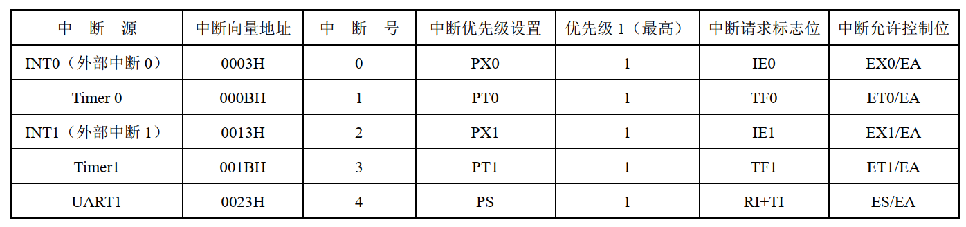
- Interrupt introduction: IAP15F2K61S2 Series MCU provides 14 interrupt request sources. There must be 5 interrupts INT0, INT1, timer 0 / 1 and serial port interrupt in common 51 single chip microcomputer. Interrupts have priority / priority. It should be noted that low priority interrupts can be interrupted by high priority interrupts, and vice versa. Any kind of interrupt (whether high-level or low-level), once responded, will not be interrupted by its peer interrupt. When two interrupts with the same priority are generated at the same time, the interrupt query order will determine which interrupt the system responds to first. Interrupt number (full name: interrupt query order). Interrupt number is very important in programming. When an interrupt comes, only the correct interrupt number can enter the interrupt. For the names and functions of some special registers, please refer to the "Blue Bridge Cup" national software and information technology professionals competition (Electronics) training guide, which will not be repeated here.
- When an interrupt is triggered, it will enter the interrupt service function. The general form of the interrupt service function is: void function name () [interrupt n], n represents the interrupt number
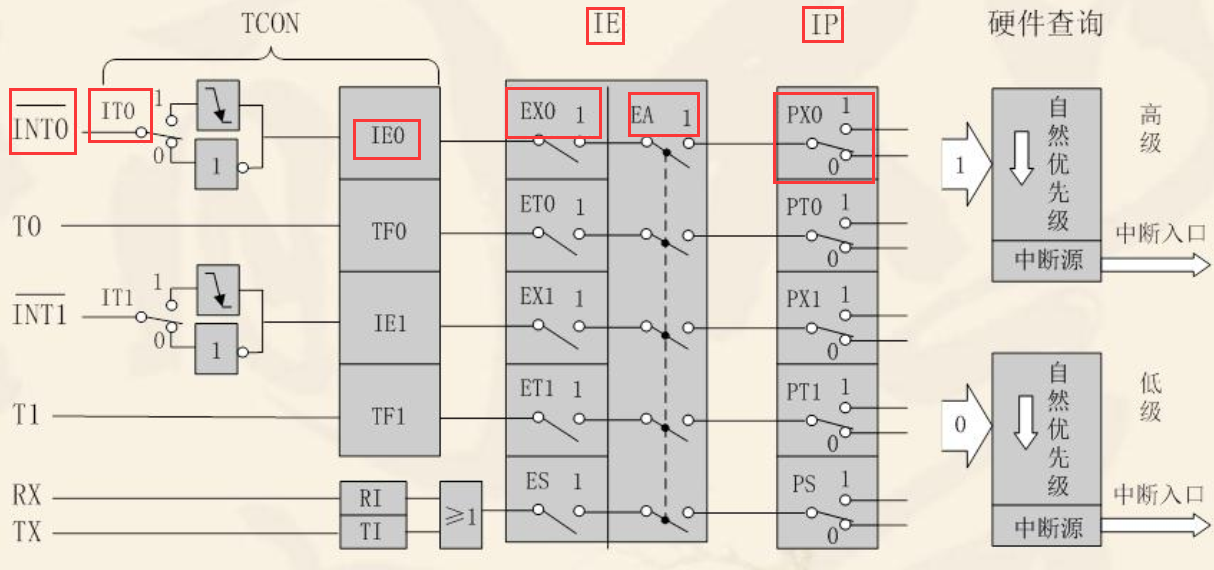
- External interrupt configuration: the internal block diagram of 51 single chip microcomputer series is shown below, taking the external interrupt INT0 as an example. The interrupt source type selection bit IT0 of external interrupt 0 in timer / counter control register TCON selects whether it is valid at low level or valid at falling edge. When the CPU detects that there is a valid interrupt signal, the external interrupt 0 (INT0/P3.2) interrupt request flag IE0 is set to 1 (internal detection, no need for our software operation to set 1) and applies to the CPU for interrupt. Next, go to the interrupt permission register IE and set the external interrupt 0 permission bit EX0 to 1. Turn on the total interrupt permission bit EA and set it to 1. The interrupt priority control register IP MCU has met the requirements and does not need to be adjusted manually.
-
Note to implementation: since the independent key in this experiment needs to control the LED, the latch end LE is at the high level, that is, Y4C is controlled at the high level. As shown in the figure below, Y4C is controlled by Y4, and the WR input is fixed at the low level (0). Understand the digital circuit NOR gate Knowledge, we have to make Y4 output low level to make Y4C output high level, and Y4 is a pin of 74HC138 chip (38 decoder). Referring to the corresponding chip manual, we can see that its truth table meets C = 1, B = 0, A = 0 (corresponding pins P27, P26, P25) to make Y4 output low level, At the same time, when implementing the code, ensure that the other pins (0 ~ 4) of pin P2 remain in the original state.
-
Note: ① select BTN for key function (jumper 2 and 3 on J5 are connected, and then switch to S7, S6, S5 and S4 independent key modules) ② select jumper J13 for peripheral access mode, select 2 and 3 short circuit, that is, select I/O direct control mode ③ reset select strip J15, select 1 and 2 short circuit, that is, select 51 series single chip microcomputer.
Experimental procedure
The external interrupt controls the state reversal of L1 and L2
//config.h -- used to declare header files, functions, variables that are often used or statements that are difficult to write
#ifndef _CONFIG_H
#define _CONFIG_H
#include <STC15F2K60S2. H> / / corresponding to the chip function header file, some special function registers are defined
#include<intrins.h>
//typedef unsigned char uchar;
#define uchar unsigned char
void Delay10ms();		//@12.000MHz

#endif
//main.c -- external interrupt 0 and 1 control L1 and L2 on and off respectively. It should be noted that P32 is external interrupt 0 control and P33 is external interrupt 1 control

//main.c -- external interrupt 0 and 1 control L1 and L2 on and off respectively. It should be noted that P32 is controlled by external interrupt 0 and P33 is controlled by external interrupt 1

#include "config.h"

uchar ucled;//Global variable, which is automatically initialized to 0


void close_peripheral()//Turn off peripherals -- LED initialization goes out, buzzer does not sound, relay does not adsorb
{
	P2 = (P2 & 0x1f) | 0x80;//Open Y4C
	P0 = 0xff;
	P2 &= 0x1f;

	P2 = (P2 & 0x1f) | 0xa0;
	P0 = 0;
	P2 &= 0x1f;
}


void Int0_init()
{
	IT0 = 1;//The external interrupt source type selection bit of external interrupt 0 is set as falling edge trigger
	EX0 = 1;//The interrupt enable bit EX0 of external interrupt 0 is set to 1
	EA = 1;//Total clock out interrupt
}

void Int1_init()
{
   	IT1 = 1;//INT1 interrupt source type selection bit setting bit falling edge trigger
   	EX1 = 1;//The interrupt enable bit EX1 of INT1 is set to 1
	EA = 1;//Total interruption of clock in
}

void main()
{
	close_peripheral();
	Int0_init();
	Int1_init();
	while(1);
}

void Delay10ms()		//@12.000MHz
{
	unsigned char i, j;

	i = 117;
	j = 184;
	do
	{
		while (--j);
	} while (--i);
}


void Int0() interrupt 0
{
	if (0 == P32)
	{
		Delay10ms();//S5 key debounce
		if (0 == P32)
		{
			ucled ^= 1;//The XOR operator only changes the lowest state. The difference is 1 and the same is 0
			P0 = ~ucled;
			P2 = (P2 & 0x1f) | 0x80;
			P2 &= 0x1f;
		}
	}
}


void Int1() interrupt 2
{
  if (0 == P33)
  {
   	 Delay10ms();//S4 key debounce
	 if (0 == P33)
	 {
	 	 ucled ^= 2;//The XOR operator only changes the state of the penultimate bit. The difference is 1 and the same is 0
		 P0 = ~ucled;
		 P2 = (P2 & 0x1f) | 0x80;
		 P2 &= 0x1f;
	 }
  }

}
External interrupt control buzzer and relay
//config.h -- used to declare header files, functions, variables that are often used or statements that are difficult to write
#ifndef _CONFIG_H
#define _CONFIG_H
#include <STC15F2K60S2. H> / / corresponding to the chip function header file, some special function registers are defined
#include<intrins.h>
//typedef unsigned char uchar;
#define uchar unsigned char
void Delay20ms();		//@12.000MHz

#endif
//main.c -- external interrupt 0 and 1 respectively control whether the buzzer sounds and whether the relay is adsorbed. It should be noted that P32 is controlled by external interrupt 0 and P33 is controlled by external interrupt 1

#include "config.h"

uchar ucled;//Global variable, which is automatically initialized to 0

void close_peripheral()//Turn off peripherals -- LED initialization is off, buzzer does not sound, relay does not adsorb
{
	P2 = (P2 & 0x1f) | 0x80;//Open Y4C
	P0 = 0xff;
	P2 &= 0x1f;

	P2 = (P2 & 0x1f) | 0xa0;
	P0 = 0;
	P2 &= 0x1f;
}


void Int_init()
{
	IT0 = 1;//The external interrupt source type selection bit of external interrupt 0 is set as falling edge trigger
	IT1 = 1;//INT1 interrupt source type selection bit setting bit falling edge trigger
	EX0 = 1;//The interrupt enable bit EX0 of external interrupt 0 is set to 1
	EX1 = 1;//The interrupt enable bit EX1 of INT1 is set to 1
	EA = 1;//Total interruption of clock in
}


void main()
{
	close_peripheral();
	Int_init();
	while(1);
}

void Delay20ms()		//@12.000MHz
{
	unsigned char i, j, k;

	_nop_();
	_nop_();
	i = 1;
	j = 234;
	k = 113;
	do
	{
		do
		{
			while (--k);
		} while (--j);
	} while (--i);
}


void Int0() interrupt 0
{
	if (0 == P32)
	{
		Delay20ms();//S5 key debounce
		if (0 == P32)
		{
			ucled ^= 0x40;//Bit P06 controls whether the buzzer sounds
			P0 = ~ucled;
			P2 = (P2 & 0x1f) | 0xa0;
			P2 &= 0x1f;
		}
	}
}

void Int1() interrupt 2
{
  if (0 == P33)
  {
   	 Delay20ms();//S4 key debounce
	 if (0 == P33)
	 {
	 	 ucled ^= 0x10;//P04 position, whether the control relay is adsorbed
		 P0 = ~ucled;
		 P2 = (P2 & 0x1f) | 0xa0;
		 P2 &= 0x1f;
	 }
  }

}