1, Basic knowledge of serial communication
1. Serial communication interface of STM32.
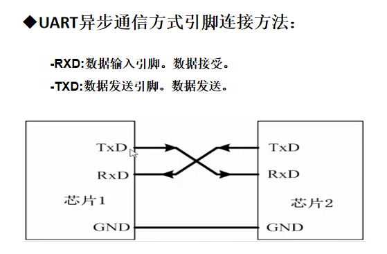
UART: universal asynchronous transceiver.
USART: universal synchronous asynchronous transceiver.
High capacity STM32F10x series chips, including 3 USART s and 2 UART S.
2. Connection mode between communication pin RXD and TXD
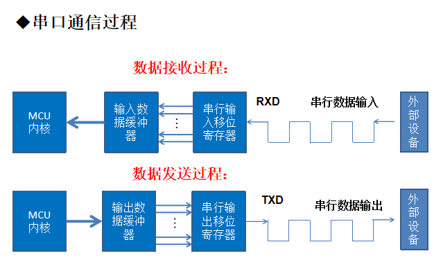
3. Communication data flow process
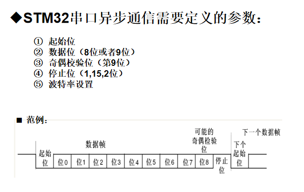
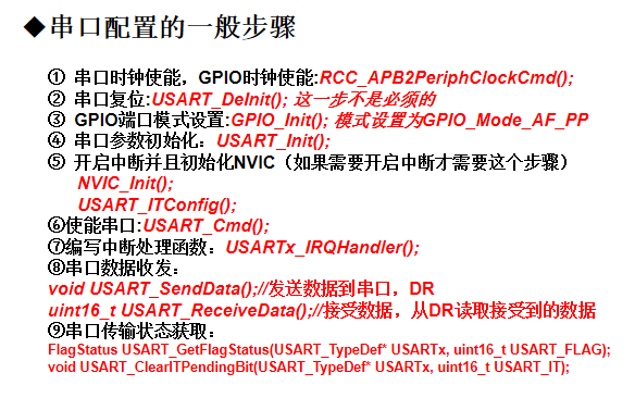
4. Serial port parameters to be configured
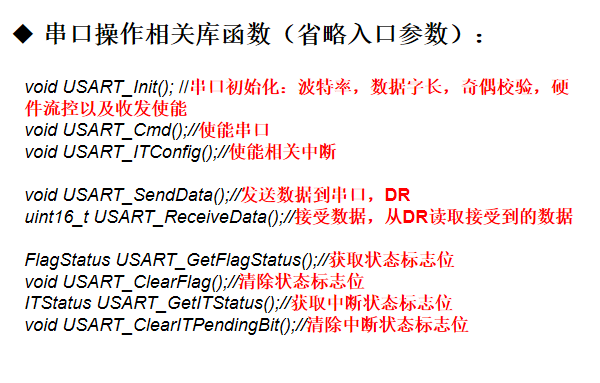
5. Library functions related to serial port
6. Steps for initializing serial port of library function
6. Code
void uart_init1(u32 bound)
	{
    //GPIO define
    GPIO_InitTypeDef GPIO_InitStructure;
	  USART_InitTypeDef USART_InitStructure;
	  NVIC_InitTypeDef NVIC_InitStructure;

	  RCC_APB2PeriphClockCmd(RCC_APB2Periph_USART1|RCC_APB2Periph_GPIOA, ENABLE);	//open USART1,GPIOA clk
 	  USART_DeInit(USART1);  //release uart1
	 //USART1_TX   PA.9
    GPIO_InitStructure.GPIO_Pin = GPIO_Pin_9; //PA.9
    GPIO_InitStructure.GPIO_Speed = GPIO_Speed_50MHz;
    GPIO_InitStructure.GPIO_Mode = GPIO_Mode_AF_PP;	//output mode
    GPIO_Init(GPIOA, &GPIO_InitStructure); // Set PA9

    //USART1_RX	  PA.10
    GPIO_InitStructure.GPIO_Pin = GPIO_Pin_10;
    GPIO_InitStructure.GPIO_Mode =GPIO_Mode_IN_FLOATING;//
    GPIO_Init(GPIOA, &GPIO_InitStructure);  //Set PA10

   //Usart1 NVIC

  NVIC_InitStructure.NVIC_IRQChannel = USART1_IRQn;
	NVIC_InitStructure.NVIC_IRQChannelPreemptionPriority=4 ;//
	NVIC_InitStructure.NVIC_IRQChannelSubPriority = 0;		//
	NVIC_InitStructure.NVIC_IRQChannelCmd = ENABLE;			//
	NVIC_Init(&NVIC_InitStructure);	//

   //USART1

	USART_InitStructure.USART_BaudRate = bound;//9600;
	USART_InitStructure.USART_WordLength = USART_WordLength_8b;//
	USART_InitStructure.USART_StopBits = USART_StopBits_1;//
	USART_InitStructure.USART_Parity = USART_Parity_No;//
	USART_InitStructure.USART_HardwareFlowControl = USART_HardwareFlowControl_None;//
	USART_InitStructure.USART_Mode = USART_Mode_Rx | USART_Mode_Tx;	//

    USART_Init(USART1, &USART_InitStructure); //
    USART_ITConfig(USART1, USART_IT_RXNE, ENABLE);//
    USART_Cmd(USART1, ENABLE);                    //

}
2, Ultrasonic Fundamentals
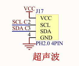
SR04 is a distance sensor using ultrasonic characteristics. It has two ultrasonic probes, which are used for transmitting and receiving ultrasonic waves respectively. The measurement range is 3-500cm.
1. Basic principles
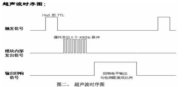
(1) Firstly, use the digital pin 13 of STM32 to input a high-level signal of at least 10us to the TRIG pin to trigger the ranging function of the module.
(2) After the ranging function is triggered, the module will automatically send 8 40kHz ultrasonic pulses and automatically detect whether there is a signal return. This step is automatically completed inside the module.
(3) Once an ECHO signal is detected, the ECHO pin will output a high level. The duration of the high level is the time from the transmission to the return of the ultrasonic wave. At this time, the timer can be used to obtain the time of the high level and calculate the actual distance from the measured object. Formula: distance = high level time * sound speed (340M/S)/2.
2. Circuit diagram
3. Library function writing process
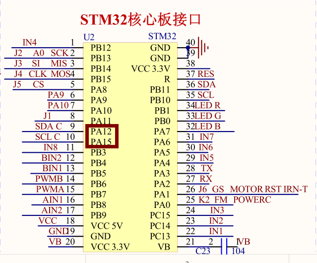
(1) Initialize the ultrasonic pin and turn on the corresponding pin clock.
(2) Since it is necessary to use the timer to measure the time of the returned high level, it is necessary to initialize the timer (with a cycle of 1ms).
(3) According to the formula: distance = high level time * sound speed (340M/S)/2, so it is also necessary to write a function to convert the measured time into distance, measure five times and take the average value.
3, Overall programming flow
1. Serial port initialization (with interruption), open the serial port.
2. Ultrasonic pin initialization.
3. Timer initialization (with interrupt).
4. Preparation of ranging function
4. Main function output
4, Code (detailed comments)
main.c
#include "motor.h"
#include "stdio.h"
#include "delay.h"
#include "stm32f10x.h"
#include "followline.h"
#include "sys.h"
#include "ultrasonic.h"

u8 UART3_data,UART1_data;
u8 UART3_rcv[20],UART3_rcv_count;
u8 UART1_rcv[50],UART1_rcv_count,Uart1_finish;

int main(void)
{
	float length;
	delay_init();//Delay initialization
	uart_init1(9600);//Serial port initialization
	ultrasonic_gpio_init();//Ultrasonic pin initialization
	ultrasonic_time2_init();//Ultrasonic timer initialization

	while(1)
	{

    printf("start  work!!\n");
		length=transfer_ditigal();
		printf("distance:%fcm\n",length);
		delay_s(1);

	}
}
ultrasonic.c
#include "ultrasonic.h"
#include "stm32f10x_tim.h"
#include "stm32f10x_rcc.h"

int overcount;//Count variable

/************************Ultrasonic pin initialization***************************************/

void ultrasonic_gpio_init(void)
{
	//Ultrasonic transmitting pin

	//Define GPIO_A initialized structure
	GPIO_InitTypeDef GPIO_InitStruct_A;
	 //Turn on the clock of PA pin
	 RCC_APB2PeriphClockCmd(RCC_APB2Periph_GPIOA, ENABLE);
   RCC_APB2PeriphClockCmd(RCC_APB2Periph_AFIO, ENABLE);
	 //Turn off the special function of pin PB4
	 GPIO_PinRemapConfig(GPIO_Remap_SWJ_JTAGDisable,ENABLE);
  //	GPIO_PinRemapConfig(GPIO_Remap_SWJ_JTAGDisable,ENABLE);
	 //Configure parameters of PA15
	GPIO_InitStruct_A.GPIO_Mode=GPIO_Mode_Out_PP;
	GPIO_InitStruct_A.GPIO_Pin=GPIO_Pin_15;
	GPIO_InitStruct_A.GPIO_Speed=GPIO_Speed_50MHz;
	 //Initialize PA15 pin
	GPIO_Init(GPIOA, &GPIO_InitStruct_A);
	 //Set PA15 low
	GPIO_ResetBits(GPIOA, GPIO_Pin_15);


	//Ultrasonic receiving pin

	//Configure parameters of PA12
  GPIO_InitStruct_A.GPIO_Mode=GPIO_Mode_IPD;
	GPIO_InitStruct_A.GPIO_Pin=GPIO_Pin_12;
	//Initialize PA12 pin
	GPIO_Init(GPIOA, &GPIO_InitStruct_A);

}
/************************************************************************************************************/

/********************************The ultrasound is initialized using timer 2*******************************************************/
void ultrasonic_time2_init(void)
{

	//Define TIME_2 initialized structure
	TIM_TimeBaseInitTypeDef  TIM_TimeBaseInitStruct_TIME2;
	//Turn on the clock of timer 2
	RCC_APB1PeriphClockCmd(RCC_APB1Periph_TIM2,ENABLE);
	//Configure time_ Parameters of 2
	TIM_TimeBaseInitStruct_TIME2.TIM_ClockDivision=TIM_CKD_DIV1;
	TIM_TimeBaseInitStruct_TIME2.TIM_CounterMode=TIM_CounterMode_Up;
	TIM_TimeBaseInitStruct_TIME2.TIM_Period=999;
	TIM_TimeBaseInitStruct_TIME2.TIM_Prescaler=71;
	//Initialize time_ two
	TIM_TimeBaseInit(TIM2,&TIM_TimeBaseInitStruct_TIME2);
  //Defines the structure of NVIC initialization
	NVIC_InitTypeDef NVIC_InitStruct;
	//Interrupt packet
	NVIC_PriorityGroupConfig(NVIC_PriorityGroup_4);
	//Configure parameters of NVIC
	NVIC_InitStruct.NVIC_IRQChannel=TIM2_IRQn;
	NVIC_InitStruct.NVIC_IRQChannelCmd=ENABLE;
	NVIC_InitStruct.NVIC_IRQChannelPreemptionPriority=2;
	NVIC_InitStruct.NVIC_IRQChannelSubPriority=0;
	//Interrupt initialization of NVIC
	NVIC_Init(&NVIC_InitStruct);
	//Clear timer TIME_2 update interrupt flag
	TIM_ClearITPendingBit(TIM2, TIM_IT_Update);
	//Start timer TIME_2 interrupt
	TIM_ITConfig(TIM2, TIM_IT_Update, ENABLE);
	 //Enable timer time_ two
  //TIM_Cmd(TIM2,ENABLE );

}
/*************************************************************************************************************************/

/*********************************************Distance measurement function*********************************************************************/
float transfer_ditigal(void)
{

  float length =0,sum=0;
  u16 time;
  unsigned int i=0;
/*Measure the data for 5 times and calculate the average value once*/
	while(i!=5)
	{
    GPIO_SetBits(GPIOA,GPIO_Pin_15);//Pull up signal as trigger signal
		delay_us(20);//High level signal exceeds 10us
    GPIO_ResetBits(GPIOA,GPIO_Pin_15);
/*Waiting for echo signal*/
   while(GPIO_ReadInputDataBit(GPIOA,GPIO_Pin_12) ==RESET);
		TIM_Cmd(TIM2,ENABLE);//When the echo signal arrives, turn on the timer to count
    i+=1; //The average value is calculated every time the echo signal is received + 1 and 5 times
    while(GPIO_ReadInputDataBit(GPIOA,GPIO_Pin_12)== SET);//Echo signal disappears
		TIM_Cmd(TIM2,DISABLE) ;//off timer
    time=TIM_GetCounter(TIM2);//Obtain the count value in the count TIw2 register and calculate the echo signal time
    length=(time+overcount*1000)/58.0;//Calculate the distance from the echo signal
     sum=length+sum;
    TIM2->CNT = 0; //Clear the count value of tiem2 count register
		overcount = 0;//Reset interrupt overflow times
     delay_ms(1);
	}
    length =sum/5;
	  return length;//Distance as a function return value
}
/**********************************************************************************************************************/


void TIM2_IRQHandler()   //TIM2 interrupt
{
    if (TIM_GetITStatus(TIM2, TIM_IT_Update))//Check whether the TIM2 update interrupt occurs
        {
						 TIM_ClearITPendingBit(TIM2, TIM_IT_Update);//Clear TIM2 update interrupt flag
					   overcount++;
				}
}
ultrasonic.h
#ifndef __ULTRASONIC_H
#define __ULTRASONIC_H

#include "stm32f10x_tim.h"
#include "stm32f10x_rcc.h"
#include "delay.h"
#include "stm32f10x.h"
#include "stm32f10x_gpio.h"

float transfer_ditigal(void);//Distance display
void ultrasonic_gpio_init(void);//Ultrasonic pin initialization
void ultrasonic_time2_init(void);//Ultrasonic timer initialization

#endif
usart.c
#include "sys.h"
#include "ultrasonic.h"
#include "stdio.h"
#include "sys.h"
#include "usart.h"
extern u8 UART3_data,UART1_data;
extern u8 UART3_rcv[20],UART3_rcv_count;
extern u8 UART1_rcv[50],UART1_rcv_count,Uart1_finish;
//uart1
//bound:9600

//Add the following code to support the printf function without selecting use MicroLIB
#if 1
#pragma import(__use_no_semihosting)
//Support functions required by the standard library
struct __FILE
{
	int handle;

};

FILE __stdout;
//Definition_ sys_exit() to avoid using half host mode

void _sys_exit (int  x)
{
	x = x;
}
//Redefine fputc function
int fputc(int ch, FILE *f)
{
	  while((USART1->SR&0X40)==0)
			;                    //Cycle sending until sending is completed
    USART1->DR = (u8) ch;
	  return ch;
}
#endif

void uart_init1(u32 bound)
	{
    //GPIO define
    GPIO_InitTypeDef GPIO_InitStructure;
	  USART_InitTypeDef USART_InitStructure;
	  NVIC_InitTypeDef NVIC_InitStructure;

	  RCC_APB2PeriphClockCmd(RCC_APB2Periph_USART1|RCC_APB2Periph_GPIOA, ENABLE);	//open USART1,GPIOA clk
 	  USART_DeInit(USART1);  //release uart1
	 //USART1_TX   PA.9
    GPIO_InitStructure.GPIO_Pin = GPIO_Pin_9; //PA.9
    GPIO_InitStructure.GPIO_Speed = GPIO_Speed_50MHz;
    GPIO_InitStructure.GPIO_Mode = GPIO_Mode_AF_PP;	//output mode
    GPIO_Init(GPIOA, &GPIO_InitStructure); // Set PA9

    //USART1_RX	  PA.10
    GPIO_InitStructure.GPIO_Pin = GPIO_Pin_10;
    GPIO_InitStructure.GPIO_Mode =GPIO_Mode_IN_FLOATING;//
    GPIO_Init(GPIOA, &GPIO_InitStructure);  //Set PA10

   //Usart1 NVIC

  NVIC_InitStructure.NVIC_IRQChannel = USART1_IRQn;
	NVIC_InitStructure.NVIC_IRQChannelPreemptionPriority=4 ;//
	NVIC_InitStructure.NVIC_IRQChannelSubPriority = 0;		//
	NVIC_InitStructure.NVIC_IRQChannelCmd = ENABLE;			//
	NVIC_Init(&NVIC_InitStructure);	//

   //USART1

	USART_InitStructure.USART_BaudRate = bound;//9600;
	USART_InitStructure.USART_WordLength = USART_WordLength_8b;//
	USART_InitStructure.USART_StopBits = USART_StopBits_1;//
	USART_InitStructure.USART_Parity = USART_Parity_No;//
	USART_InitStructure.USART_HardwareFlowControl = USART_HardwareFlowControl_None;//
	USART_InitStructure.USART_Mode = USART_Mode_Rx | USART_Mode_Tx;	//

    USART_Init(USART1, &USART_InitStructure); //
    USART_ITConfig(USART1, USART_IT_RXNE, ENABLE);//
    USART_Cmd(USART1, ENABLE);                    //

}

//uart3
//bound:9600
void uart_init3(u32 bound){
    //GPIO
    GPIO_InitTypeDef GPIO_InitStructure;
	USART_InitTypeDef USART_InitStructure;
	NVIC_InitTypeDef NVIC_InitStructure;

	RCC_APB1PeriphClockCmd(RCC_APB1Periph_USART3, ENABLE);	//open USART3 clk
	RCC_APB2PeriphClockCmd(RCC_APB2Periph_GPIOB, ENABLE);	//open GPIOB clk
 	USART_DeInit(USART3);  //release uart3
	 //USART3_TX   PB.10
    GPIO_InitStructure.GPIO_Pin = GPIO_Pin_10; //PB.10
    GPIO_InitStructure.GPIO_Speed = GPIO_Speed_50MHz;
    GPIO_InitStructure.GPIO_Mode = GPIO_Mode_AF_PP;	//output mode
    GPIO_Init(GPIOB, &GPIO_InitStructure); //configure PB10

    //USART3_RX	  PB.11
    GPIO_InitStructure.GPIO_Pin = GPIO_Pin_11;
    GPIO_InitStructure.GPIO_Mode = GPIO_Mode_IN_FLOATING;//input mode
    GPIO_Init(GPIOB, &GPIO_InitStructure);  //configure PB11

   //Usart3 NVIC

    NVIC_InitStructure.NVIC_IRQChannel = USART3_IRQn;
	NVIC_InitStructure.NVIC_IRQChannelPreemptionPriority=5 ;//
	NVIC_InitStructure.NVIC_IRQChannelSubPriority = 0;		//
	NVIC_InitStructure.NVIC_IRQChannelCmd = ENABLE;			//
	NVIC_Init(&NVIC_InitStructure);	//

   //USART

	USART_InitStructure.USART_BaudRate = bound;//9600;
	USART_InitStructure.USART_WordLength = USART_WordLength_8b;//data bit
	USART_InitStructure.USART_StopBits = USART_StopBits_1;//stop bit
	USART_InitStructure.USART_Parity = USART_Parity_No;//
	USART_InitStructure.USART_HardwareFlowControl = USART_HardwareFlowControl_None;//
	USART_InitStructure.USART_Mode = USART_Mode_Rx | USART_Mode_Tx;	//

    USART_Init(USART3, &USART_InitStructure); //
    USART_ITConfig(USART3, USART_IT_RXNE, ENABLE);//
    USART_Cmd(USART3, ENABLE);                    //

}

void USART1_SendByByter(u8 Data)
{
	//
	USART_GetFlagStatus(USART1, USART_FLAG_TC);
	USART_SendData(USART1, Data);
	while (USART_GetFlagStatus(USART1, USART_FLAG_TC) == RESET);
}

void USART3_SendByByter(u8 Data)
{
	//
	USART_GetFlagStatus(USART3, USART_FLAG_TC);
	USART_SendData(USART3, Data);
	while (USART_GetFlagStatus(USART3, USART_FLAG_TC) == RESET);
}

void USART1_IRQHandler(void)                	//uart1 ISR
	{
		u8 Res;
		if(USART_GetITStatus(USART1, USART_IT_RXNE) != RESET)  //
		{
		  Res =USART_ReceiveData(USART1);//(USART1->DR);	//
		  UART1_data=Res;
		if(Res==0x7E && UART1_rcv_count==0)
		{
       UART1_rcv[UART1_rcv_count++]=Res;

    }
    else if(Res!=0x7E && UART1_rcv_count>0)
    {
      UART1_rcv[UART1_rcv_count++]=Res;

    }
    else if(Res==0x7E && UART1_rcv_count>0)
    {
       UART1_rcv[UART1_rcv_count++]=Res;
			 Uart1_finish=2;
		 }
    else
      ;
	 }
 }


void USART3_IRQHandler(void)                	//uart3 ISR
	{
		if(USART_GetITStatus(USART3, USART_IT_RXNE) != RESET)  //RX set
		{
		UART3_data=USART_ReceiveData(USART3);//(USART1->DR);	//
		UART3_rcv[UART3_rcv_count]=UART3_data;
		if(UART3_rcv_count<6) UART3_rcv_count++;

    }
	}
sys.h
#ifndef __SYS_H
#define __SYS_H
#include "stm32f10x.h"
//
//This program is only for learning and use, and shall not be used for any other purpose without the permission of the author
//ALIENTEK STM32 development board
//Punctual atom @ ALIENTEK
//Technical Forum: www.openedv.com com
//Modified on: August 18, 2012
//Version: v1.0 seven
//Copyright, piracy must be investigated.
//Copyright(C) Guangzhou Xingyi Electronic Technology Co., Ltd. 2009-2019
//All rights reserved
//

//0, ucos is not supported
//1. Support ucos
#define SYSTEM_SUPPORT_OS 		 0 		// Defines whether the system folder supports UCOS


//Bit band operation to achieve 51 similar GPIO control functions
//For specific implementation ideas, refer to Chapter 5 of < < cm3 authoritative guide > > (page 87 ~ 92)
//IO port operation macro definition
#define BITBAND(addr, bitnum) ((addr & 0xF0000000)+0x2000000+((addr &0xFFFFF)<<5)+(bitnum<<2))
#define MEM_ADDR(addr)  *((volatile unsigned long  *)(addr))
#define BIT_ADDR(addr, bitnum)   MEM_ADDR(BITBAND(addr, bitnum))
//IO port address mapping
#define GPIOA_ODR_Addr    (GPIOA_BASE+12) //0x4001080C
#define GPIOB_ODR_Addr    (GPIOB_BASE+12) //0x40010C0C
#define GPIOC_ODR_Addr    (GPIOC_BASE+12) //0x4001100C
#define GPIOD_ODR_Addr    (GPIOD_BASE+12) //0x4001140C
#define GPIOE_ODR_Addr    (GPIOE_BASE+12) //0x4001180C
#define GPIOF_ODR_Addr    (GPIOF_BASE+12) //0x40011A0C
#define GPIOG_ODR_Addr    (GPIOG_BASE+12) //0x40011E0C

#define GPIOA_IDR_Addr    (GPIOA_BASE+8) //0x40010808
#define GPIOB_IDR_Addr    (GPIOB_BASE+8) //0x40010C08
#define GPIOC_IDR_Addr    (GPIOC_BASE+8) //0x40011008
#define GPIOD_IDR_Addr    (GPIOD_BASE+8) //0x40011408
#define GPIOE_IDR_Addr    (GPIOE_BASE+8) //0x40011808
#define GPIOF_IDR_Addr    (GPIOF_BASE+8) //0x40011A08
#define GPIOG_IDR_Addr    (GPIOG_BASE+8) //0x40011E08

//IO port operation, only for a single IO port!
//Make sure that the value of n is less than 16!
#define PAout(n)   BIT_ADDR(GPIOA_ODR_Addr,n) / / output
#define PAin(n)    BIT_ADDR(GPIOA_IDR_Addr,n) / / input

#define PBout(n)   BIT_ADDR(GPIOB_ODR_Addr,n) / / output
#define PBin(n)    BIT_ADDR(GPIOB_IDR_Addr,n) / / input

#define PCout(n)   BIT_ADDR(GPIOC_ODR_Addr,n) / / output
#define PCin(n)    BIT_ADDR(GPIOC_IDR_Addr,n) / / input

#define PDout(n)   BIT_ADDR(GPIOD_ODR_Addr,n) / / output
#define PDin(n)    BIT_ADDR(GPIOD_IDR_Addr,n) / / input

#define PEout(n)   BIT_ADDR(GPIOE_ODR_Addr,n) / / output
#define PEin(n)    BIT_ADDR(GPIOE_IDR_Addr,n) / / enter

#define PFout(n)   BIT_ADDR(GPIOF_ODR_Addr,n) / / output
#define PFin(n)    BIT_ADDR(GPIOF_IDR_Addr,n) / / input

#define PGout(n)   BIT_ADDR(GPIOG_ODR_Addr,n) / / output
#define PGin(n)    BIT_ADDR(GPIOG_IDR_Addr,n) / / input

void USART1_SendByByter(u8 Data);
void uart_init1(u32 bound);

#endif
Finally, Xiaobai's study notes are welcome for advice.