preface
In the previous blog, I combed ALOAM: motion distortion compensation of lidar link
In ALOAM, only lidar is used as the sensor, so the position and attitude matching between frames can be used to compensate the data of the next frame
For example, the pose transformation from k-1 frame to K frame is obtained through inter frame matching Then when the k+1 frame comes, the pose transformation is regarded as the pose transformation between the start point and the end point of the k+1 frame, and then the pose of each point is linearly interpolated through the time of each point, and finally the compensation calculation is made
The direct matching algorithm needs to make an assumption that the robot moves at a uniform speed Otherwise, why is the pose between frames at the last time the pose at the start and end of the frame
This assumption is reasonable when the robot really moves at a uniform speed or the lidar updates quickly
When there are other sensors on the robot, such as wheel speed odometer or IMU, the motion distortion compensation of lidar can be carried out with the assistance of other sensors
This blog mainly explains how to use wheel speed odometer to compensate the motion distortion of lidar
There are theoretical explanations and code examples
Basic theory
Lidar data will be affected when the robot is moving Distortion occurs and the data cannot reflect the real situation When matching with data again, there will be an error
Causes:
- Laser point data is not obtained instantaneously
- Laser measurement is accompanied by the movement of the robot
- When the laser frame rate is low, the motion of the robot can not be ignored
Distortion removal method:
- Pure estimation method
- Odometer auxiliary method
- Fusion method
Removal of lidar motion distortion by wheel speed odometer assistant method
Advantages of sensor assisted method (Odom/IMU):
- The extremely high pose update frequency (200Hz) can accurately reflect the movement
- High precision local pose estimation
- Completely decoupled from state estimation
Comparison between auxiliary sensor wheel speed odometer and IMU:
Wheel odometer - directly measure the displacement and angle of the robot; It has high local angle measurement accuracy; High local position measurement accuracy; The update speed is high (100Hz~200Hz)
Inertial measurement unit (IMU) - directly measure angular velocity and linear acceleration; High angular velocity measurement accuracy; The measurement frequency is extremely high (1kHz~8kHz); The accuracy of linear acceleration is too poor, and the local accuracy of quadratic integration is still very poor
So if you can use the wheel speed odometer on the ground robot, it is better than IMU
When the wheel speed odometer cannot be used, such as on UAV, the position can be solved first by the fusion of IMU and GPS, and then the motion distortion of lidar can be removed by auxiliary methods
The following describes the laser radar distortion removal through the wheel odometer
Known data
- Current frame laser start time ts,te
- Odometer data is stored in a queue in chronological order. The time stamp of the earliest odometer data at the head of the queue is < ts the time stamp of the latest odometer data > te
target
Solve the robot pose corresponding to each laser point in the current frame laser data
All laser points are converted to the same coordinate system according to the solved pose
Repackaged into a frame of laser data and released
step
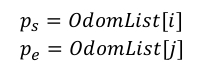
Solve the pose ps and pe at the time of ts and te
If the odometer queue is just synchronized with the laser data, assume that the time of the i and j data are ts and te respectively
But this situation basically does not exist
More often, there is no corresponding pose at the time of ts and te
If there is no corresponding odometer pose at ts time, linear interpolation is performed. If there is posture at time l and K, and l < s < K, then:
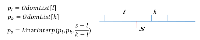
After ps and pe are obtained by linear interpolation, the pose of each point can be obtained by linear interpolation according to the time of each laser point in the current frame, but the overall linear interpolation means that the robot directly moves at a uniform speed in ts and te
Between one frame of laser data, if the robot is considered to be doing uniform acceleration, s=s0+v0t+0.5at*t. Then quadratic interpolation is more reasonable
Suppose the pose of the robot is a quadratic function of time t
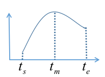
tm is the intermediate time between ts and te, so pm can be obtained by the above linear interpolation method
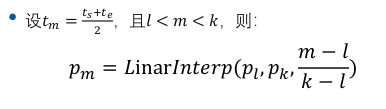
Given ps\pm\pe, you can calculate this hypothetical conic, and then you can get every point on the curve
However, in order to be closer to the actual situation, the motion of the robot is not a quadratic curve, and the acceleration will also change. Then the position and attitude of m times can be calculated directly through the linear interpolation of the odometer in ts and te

Then, the pose corresponding to each point of the lidar can be linearly interpolated piecewise in the known m+2 poses
Coordinate system I & laser data release
The pose of all points of a frame of laser data is calculated above
Then convert the data of each point to a coordinate system and publish it
Code
int main(int argc,char ** argv)
{
    ros::init(argc,argv,"LidarMotionCalib");//Initialize node

    tf::TransformListener tf(ros::Duration(10.0));//Create tf listener

    LidarMotionCalibrator tmpLidarMotionCalib(&tf);//Instantiated lidar distortion correction class

    ros::spin();
    return 0;
}
main function It's simple
Initialize node
The data of creating tf monitor wheel speed odometer will be released in the form of tf
The class correction function of instantiating lidar distortion correction is implemented in the class
Let's look at this class
+++++++++++++++++++++++++++++++++++++++++++++++++++
/* Defines the class of lidar distortion correction  */
class LidarMotionCalibrator
{
public:
    /*Constructor passed in tf listener */
    LidarMotionCalibrator(tf::TransformListener* tf)
    {
        tf_ = tf;//The listener of the private member variable tf of the assignment class obtains the odometer pose
        scan_sub_ = nh_.subscribe("champion_scan", 10, &LidarMotionCalibrator::ScanCallBack, this);//Subscribe to lidar data
    }

    /*Destructor */
    ~LidarMotionCalibrator()
    {
        if(tf_!=NULL)
            delete tf_;
    }
The name of the class is lidalmotioncalibrator
Constructor passed in tf listener
In constructor
- The listener of the private member variable tf of the assignment class obtains the odometer pose
- Subscribe to lidar data
private:
    tf::TransformListener* tf_;  //The tf listener passed in by the class constructor
    ros::NodeHandle nh_;//Node nh
    ros::Subscriber scan_sub_;//Subscription lidar handle
    pcl::PointCloud<pcl::PointXYZRGB> visual_cloud_;//pcl display point cloud
These are the four private member variables of the class
Function annotated
Then there are the public functions of the class. Subscribe to the lidar data in the constructor. After the data comes, enter the callback function
Let's look at the callback function
+++++++++++++++++++++++++++++++++++++++++++++++++++
    // Get the original laser data for processing
    void ScanCallBack(const champion_nav_msgs::ChampionNavLaserScanPtr& scan_msg)
    {
        //Convert to data needed for correction
        ros::Time startTime, endTime;//Declare the start time ts and end time te of the radar of this frame
        startTime = scan_msg->header.stamp;//Get the start time of the radar in this frame

        champion_nav_msgs::ChampionNavLaserScan laserScanMsg = *scan_msg;//Take out the radar data of this frame

        //Time to get the final point
        int beamNum = laserScanMsg.ranges.size();//Obtain the laser harness of the radar in this frame
        endTime = startTime + ros::Duration(laserScanMsg.time_increment * (beamNum - 1));//Calculate the end time of radar laserscanmsg time_ Increment is the dt between the laser radar harnesses
The main function of this is to obtain the start time of the radar laser beam of this frame and calculate the end time of the laser beam of this frame
The start time is based on the timestamp of the message package
Then obtain the dt between laser harness and harness
Calculation end time = start time + dt * between harnesses (harness-1)
        // Copy the data
        std::vector<double> angles,ranges;//Declare radar data vector angle and distance
        for(int i = beamNum - 1; i >= 0; --i)
        {
            double lidar_dist = laserScanMsg.ranges[i];//Distance to take out the laser beam
            double lidar_angle = laserScanMsg.angles[i];//Take out the angle of the laser beam

            //Remove points with too small distance and set nan points to 0
            if(lidar_dist < 0.05 || std::isnan(lidar_dist) || std::isinf(lidar_dist))
                lidar_dist = 0.0;

            ranges.push_back(lidar_dist);//Save data
            angles.push_back(lidar_angle);//Save data
        }
Copy the data
Remove the points with too small distance and nan/inf points
Save the distance and angle in two vector variables, angles and ranges respectively
        tf::Stamped<tf::Pose> visualPose;// Declare a pose in the form of tf
        if(!getLaserPose(visualPose, startTime, tf_))//Obtain the position and attitude of the radar at the beginning of the frame (in the world coordinate system)
        {
            //If it cannot be obtained, an error will be reported
            ROS_WARN("Not visualPose,Can not Calib");
            return ;
        }

        double visualYaw = tf::getYaw(visualPose.getRotation());//Extracting radar heading angle in world coordinate system

        visual_cloud_.clear();//Clear display point cloud

        /*Convert the original point cloud to the world coordinate system and press in the displayed point cloud*/
        for(int i = 0; i < ranges.size();i++)//Traverse each point
        {

            if(ranges[i] < 0.05 || std::isnan(ranges[i]) || std::isinf(ranges[i]))//Do not deal with bad points
                continue;

            double x = ranges[i] * cos(angles[i]);//Calculate x in radar coordinate system
            double y = ranges[i] * sin(angles[i]);//Calculate x in radar coordinate system

            /*Convert to world coordinate system*/
            pcl::PointXYZRGB pt;//Points in the world coordinate system
            pt.x = x * cos(visualYaw) - y * sin(visualYaw) + visualPose.getOrigin().getX();
            pt.y = x * sin(visualYaw) + y * cos(visualYaw) + visualPose.getOrigin().getY();
            pt.z = 1.0;

            // pack r/g/b into rgb
            unsigned char r = 255, g = 0, b = 0;    //red color
            unsigned int rgb = ((unsigned int)r << 16 | (unsigned int)g << 8 | (unsigned int)b);
            pt.rgb = *reinterpret_cast<float*>(&rgb);

            visual_cloud_.push_back(pt);//Press the points of the original point cloud in the world coordinate system into the display point cloud
        }
Obtain the pose at the beginning of the frame
Then, in the for loop, convert each point of the frame to the world coordinate system with the pose at the beginning, and set the color of the point to red
        //Correct
        Lidar_Calibration(ranges,angles,
                          startTime,
                          endTime,
                          tf_);
Correction function I'll take a closer look at this later
        /*Turn the corrected point cloud into the world coordinate system and press in the displayed point cloud*/
        for(int i = 0; i < ranges.size();i++)//Traverse each point
        {

            if(ranges[i] < 0.05 || std::isnan(ranges[i]) || std::isinf(ranges[i]))//Do not deal with bad points
                continue;

            double x = ranges[i] * cos(angles[i]);//Calculate x in radar coordinate system
            double y = ranges[i] * sin(angles[i]);//Calculate x in radar coordinate system

            /*Convert to world coordinate system*/
            pcl::PointXYZRGB pt;
            pt.x = x * cos(visualYaw) - y * sin(visualYaw) + visualPose.getOrigin().getX();
            pt.y = x * sin(visualYaw) + y * cos(visualYaw) + visualPose.getOrigin().getY();
            pt.z = 1.0;

            unsigned char r = 0, g = 255, b = 0;    // green color
            unsigned int rgb = ((unsigned int)r << 16 | (unsigned int)g << 8 | (unsigned int)b);
            pt.rgb = *reinterpret_cast<float*>(&rgb);

            visual_cloud_.push_back(pt);//Press the points of the corrected point cloud in the world coordinate system into the displayed point cloud
        }

        //Display
         g_PointCloudView.showCloud(visual_cloud_.makeShared());
Similar to the code in the previous block
In the for loop, convert each point of the corrected frame to the world coordinate system with the pose at the beginning, and set the color of the point to green
The whole process is like this. Let's see the realization of correction function
+++++++++++++++++++++++++++++++++++++++++++++++++++
    //Piecewise linear interpolation of lidar data
    //Lidar will be called here_ MotionCalibration()
    /**
     * @name Lidar_Calibration()
     * @brief The period of linear difference segmentation of lidar data is 5ms
     * @param ranges Set of distance values of laser beam
     * @param angle Angle value set of laser beam
     * @param startTime Time stamp of the first laser beam
     * @param endTime Time stamp of the last laser beam
     * @param *tf_
    */
    void Lidar_Calibration(std::vector<double>& ranges,
                           std::vector<double>& angles,
                           ros::Time startTime,
                           ros::Time endTime,
                           tf::TransformListener * tf_)
    {
        //Count the number of laser beams
        int beamNumber = ranges.size();

        if(beamNumber != angles.size())//The number of distances and angles must be the same
        {
            ROS_ERROR("Error:ranges not match to the angles");
            return ;
        }

        // 5ms for segmentation
        int interpolation_time_duration = 5 * 1000;

        tf::Stamped<tf::Pose> frame_start_pose;//Position and posture at starting time
        tf::Stamped<tf::Pose> frame_mid_pose;//Pose at the middle time of segmentation
        tf::Stamped<tf::Pose> frame_base_pose;//The pose of the reference coordinate system is the pose at the starting time
        tf::Stamped<tf::Pose> frame_end_pose;//Posture at the end


        double start_time = startTime.toSec() * 1000 * 1000;//Start time us
        double end_time = endTime.toSec() * 1000 * 1000;//End time us
        double time_inc = (end_time - start_time) / (beamNumber - 1); // Time interval of each laser data

        //The starting coordinates of the currently interpolated segment
        int start_index = 0;

        //The position and pose of the starting point. The reason to get the position of the starting point here is that the starting point is our base_pose
        //The reference pose of all laser points will be changed to our base_pose
        // ROS_INFO("get start pose");

        if(!getLaserPose(frame_start_pose, ros::Time(start_time /1000000.0), tf_))//Obtain the posture at the starting time
        {
            ROS_WARN("Not Start Pose,Can not Calib");
            return ;
        }

        if(!getLaserPose(frame_end_pose,ros::Time(end_time / 1000000.0),tf_))//Get the pose at the end
        {
            ROS_WARN("Not End Pose, Can not Calib");
            return ;
        }

        int cnt = 0;
        //The reference coordinate is the coordinate of the first pose
        frame_base_pose = frame_start_pose;
Count the number of laser beams
Set the time for segmentation, and set 5ms here
Each pose is defined and annotated
Calculation start time \ end time \ time between harnesses
Calculate start pose \ end pose
The reference coordinate is the coordinate of the first pose
Then traverse each point in the for loop and segment by time. When the segmentation time requirements are met, enter the correction processing of this segment
Lidar_MotionCalibration is a correction process for a segment
After processing this segment, update the start time of the next segment \ start subscript of the next segment \ start time pose of the next segment
Let's look at Lidar_MotionCalibration correction processing for a segment
+++++++++++++++++++++++++++++++++++++++++++++++++++
/**
* @brief Lidar_MotionCalibration
* Segmented function of lidar motion distortion removal;
* In this piecewise function, the robot is considered to be moving at a uniform speed;
* @param frame_base_pose Reference coordinate system after calibration
* @param frame_start_pose The pose corresponding to the first laser point in this segment
* @param frame_end_pose The pose corresponding to the last laser point in this segment
* @param ranges Laser data - distance
* @param angles Laser data - angle
* @param startIndex Subscript of the first laser point in this segment in the laser frame
* @param beam_number Number of laser points in this section
*/
void Lidar_MotionCalibration(
tf::Stamped<tf::Pose> frame_base_pose,
tf::Stamped<tf::Pose> frame_start_pose,
tf::Stamped<tf::Pose> frame_end_pose,
std::vector<double>& ranges,
std::vector<double>& angles,
int startIndex,
int& beam_number)
{
//TODO
tf::Quaternion start_q = frame_start_pose.getRotation();//Initial attitude
tf::Quaternion end_q = frame_end_pose.getRotation();//End posture
tf::Vector3 start_xy(frame_start_pose.getOrigin().getX(), frame_start_pose.getOrigin().getY(), 1);//Starting position
tf::Vector3 end_xy(frame_end_pose.getOrigin().getX(), frame_end_pose.getOrigin().getY(), 1);//End position
for (size_t i = startIndex; i < startIndex + beam_number; i++) {
tf::Vector3 mid_xy = start_xy.lerp(end_xy, (i - startIndex) / (beam_number - 1));//Position linear interpolation
tf::Quaternion mid_q = start_q.slerp(end_q, (i - startIndex) / (beam_number - 1));//Attitude linear interpolation
tf::Transform mid_frame(mid_q, mid_xy);//The interpolation results are combined into pose transformation matrix
double x = ranges[i] * cos(angles[i]);//x in the current frame coordinate system
double y = ranges[i] * sin(angles[i]);//y in the current frame coordinate system
tf::Vector3 calib_point = frame_base_pose.inverse() * mid_frame * tf::Vector3(x, y, 1);//Convert to x,y in the basic coordinate system
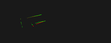
ranges[i] = sqrt(calib_point[0] * calib_point[0] + calib_point[1] * calib_point[1]);//Calculate distance
angles[i] = atan2(calib_point[1], calib_point[0]);//Calculation angle
}
//end of TODO
}
Here, the pose of the point is linearly interpolated through the sequence number of the point and the starting pose \ ending pose of the segment
Then convert the point to the basic coordinate system, and then calculate the distance and angle
Note that the interpolation of position is lerp, and the interpolation of quaternion is slerp This was mentioned in the previous blog
Over, this is the code of the whole function
+++++++++++++++++++++++++++++++++++++++++++++++++++
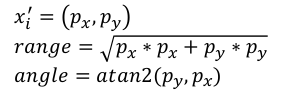
Result
After compiling, run the node Then play the data through rosbag, and you can see the data before and after correction in the visualization window of pcl
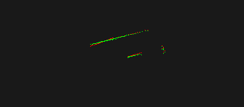

Red is the data before correction and green is the data after correction