Introduction: The micro Python PWM module of ESP32 can produce a very accurate output frequency, but all micro Python PWM share the same Timer, so their fundamental frequency is the same. Two of the hardware timers can be used with MM32 micropathon, but the frequency accuracy of the output cannot meet the requirements. Therefore: either use other signal sources to detect DTMF; Either mem32 is used to improve the accuracy of the output frequency of MM32;
Key words: MM32, micropathon, PWM, DTMF
§ 01 DTMF decoder
DTMF is a scheme for telephone dialing invented by Bell laboratory in the last century. This scheme can transmit telephone number coding through dual audio in the same telephone. stay Principle of DTMF: why choose these frequencies? These frequency selections are tested to maximize the difference between the frequency value and its harmonics.
this paper tests whether the dual audio signal with harmonics, that is, the square wave signal generated by the dual audio generated by ESP8266, can be used for the dual audio signal.
1.1 ESP8266 output dual audio
use the PWM of two channels of ESP8266 to generate dual audio, and then stack it together in different ways to test whether the signal can be decoded correctly by DTMF hardware decoder.
1.1.1 ESP32 module
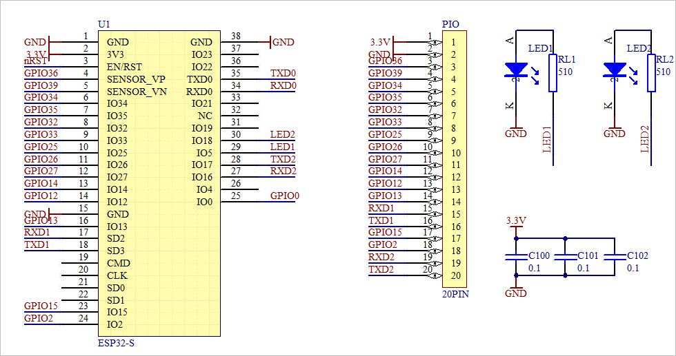
in Design and implementation of ESP32-S module adapter board The hardware design and interface of ESP32 are given.
reference Micro Python official website The programming reference of ESP32 is given.
1.1.2 generate two PWM signals
use pin17,18 of ESP32 transfer module (from the 4th and 3rd pins on the right) to output PWM waveform.
(1) Code and output results
from machine                import Pin,PWM
import time

led1 = Pin(5, Pin.OUT)
led2 = Pin(18, Pin.OUT)

lowf = [697, 770, 852, 941]
highf = [1209, 1336, 1477, 1633]

pwm1 = PWM(Pin(15), freq=lowf[0], duty=0x1ff)
pwm2 = PWM(Pin(2), freq=highf[0], duty=0x1ff)

while True:
    led1.on()
    led2.off()
    time.sleep_ms(100)
    led2.on()
    led1.off()
    time.sleep_ms(100)
(2) Existing problems
from the output result, it can be seen that the PWM corresponding to pin15 and Pin2 flows to the same PWM Timer. It can be seen that the frequency of its output PWM is the value corresponding to the last PWM frequency.
in MicroPython Machine.PWM It is given that PWM sharing the same Timer has the same fundamental frequency. Then the question comes: how to define PWM and use different timers?
in Quick reference for ESP32 PWM It is given that there can be up to 8 different PWM frequencies in ESP32, which also shows that different PWM fundamental frequencies can be set in ESP32.
in Using micropython on ESP32, how to have 2 PWM pins with different frequencies? The same question was raised. And gives a link **ports/esp32/machine_pwm: Add support for all PWM timers and modes. ** The new implementation version of esp32 micro Python is given in.
pwm3 = PWM(Pin(2), freq=440, timer=0, speed_mode=PWM.LOW_SPEED_MODE)
pwm4 = PWM(Pin(15), freq=880, timer=1, speed_mode=PWM.LOW_SPEED_MODE)
but after testing, the above functions are not supported in the current ESP32 module software.
1.2 using MM32 module
since ESP32 does not support multiple timers, use Micro Python in MM32 To experiment.
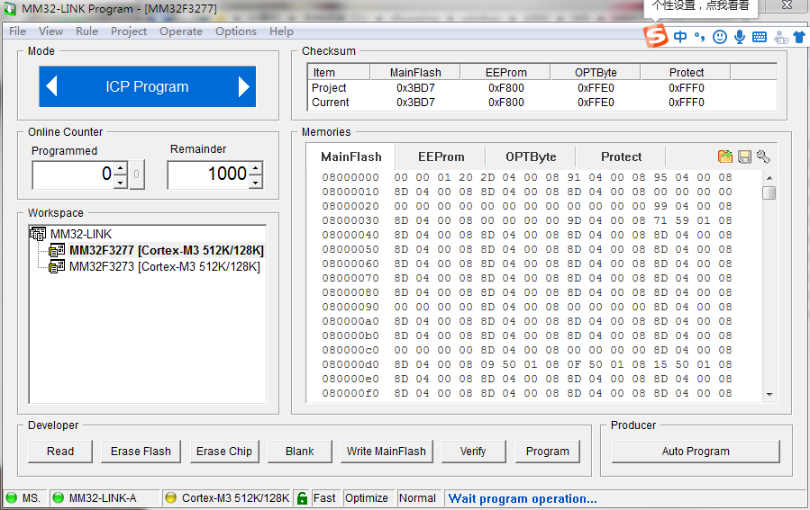
1.2.1 download the micro Python program of MM32
the latest version comes from the micro Python version of smart Su Yong:
D:\zhuoqing\window\ARM\IAR\MM32\MicroPython
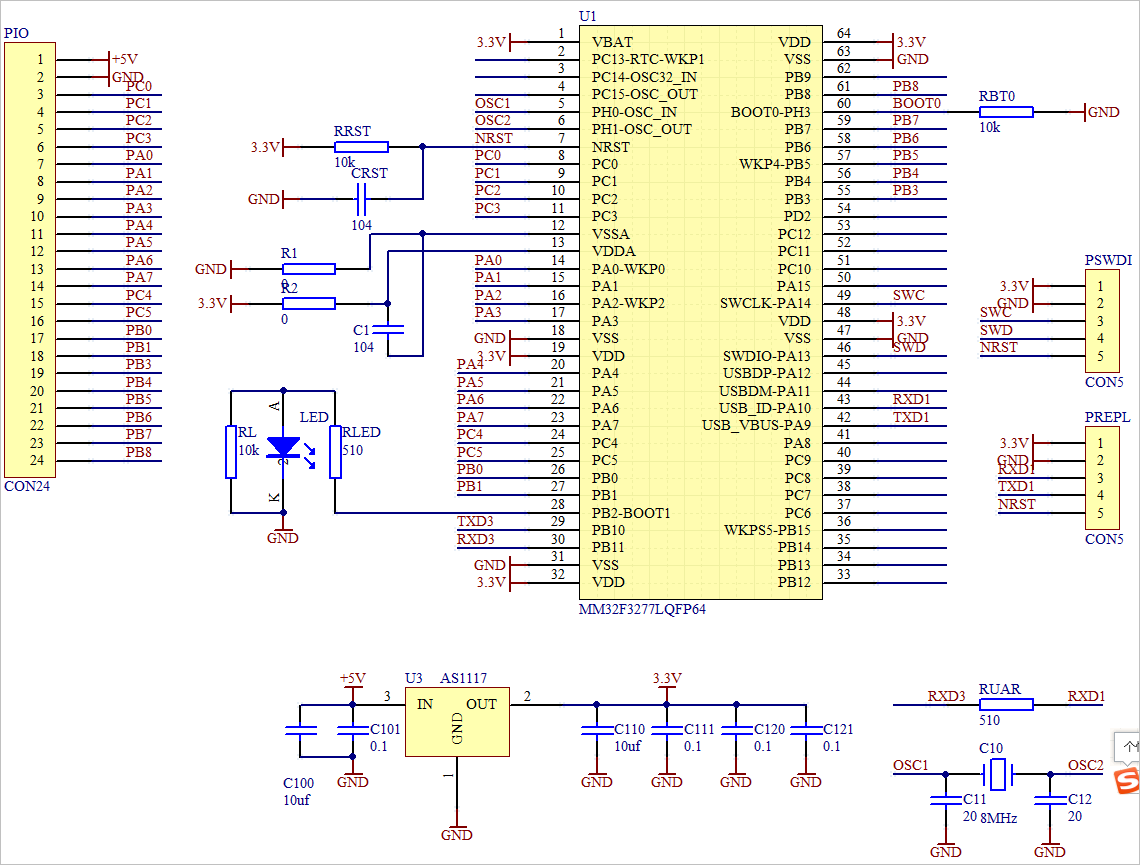
in Mm32f3277 microphoton experimental board design and software testing The circuit diagram of the experimental circuit board is given.
1.2.2 MM32 supports two PWM channels
the following table shows the two PWM in MM32. The PWM of the two channels are tested with TIM3 and TIM6 respectively, pwm0 and pwm4, TIM3 and TIM4.
| PWM | timer | GPIO |
|---|---|---|
| PWM0 | TIM3 | PA6 |
| PWM1 | TIM3 | PA7 |
| PWM2 | TIM3 | PB0 |
| PWM3 | TIM3 | PB1 |
| PWM4 | TIM4 | PB6 |
| PWM5 | TIM4 | PB7 |
| PWM6 | TIM4 | PB8 |
| PWM7 | TIM4 | PB9 |
(1) Test code
from machine                import Pin,PWM
import utime

led0 = Pin('PB2', mode=Pin.OUT_PUSHPULL)

pwm0 = PWM(0, freq=500, duty=500)
pwm1 = PWM(4, freq=501, duty=500)

print("Test PWM.")

while True:
    led0(1-led0())
    utime.sleep_ms(100)
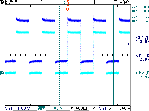
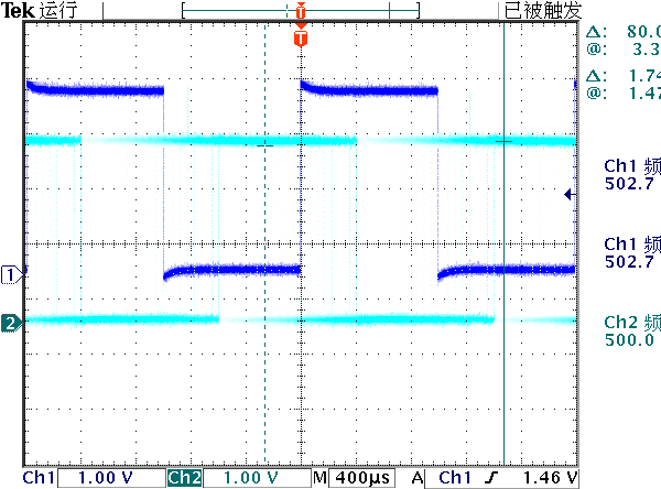
(2) Test results
(3) Existing problems
from this PWM version of Su Yong, there is an error in the output frequency. For example, set freq=490, but the output frequency is 492.3Hz.
from machine                import Pin,mem32,PWM
import utime

led = Pin('PB2', Pin.OUT_PUSHPULL)
f = 697
pwm0 = PWM(0, freq=f, duty=500)
pwm1 = PWM(4, freq=f, duty=500)

from micropython            import const
APB2PERIPH_BASE = const(0x40010000)
UART1_BASE    = const(APB2PERIPH_BASE + 0x3800)
UART1_RDR     = const(UART1_BASE + 1*4)
UART1_CSR     = const(UART1_BASE + 2*4)
replbuf = bytes(0)
def procREPL(f):
    global replbuf
    if mem32[UART1_CSR] & 0x2:
        replbuf += bytes([mem32[UART1_RDR]])
        if replbuf[-1:] == b'\r':
            f(replbuf[:-1])
            replbuf = bytes(0)
def f(s):
    global pwm0,pwm1
    frq= int(s)
    print(frq)
    pwm0.deinit()
    pwm1.deinit()
    pwm0 = PWM(0, freq=frq, duty=500)
    pwm1 = PWM(4, freq=frq, duty=500)

while True:
    procREPL(f)
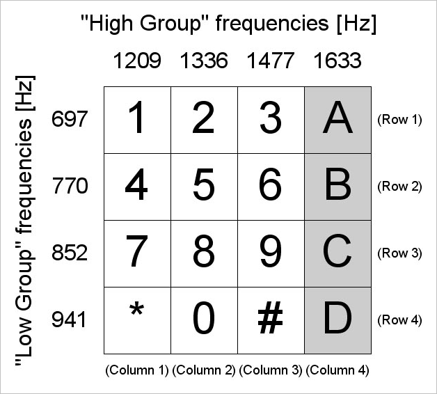
1.3 DTMF frequency coding
the following figure shows the frequency value used for DTMF coding.
1.3.1 measuring mm32 microphoton frequency
measure the square wave frequency of mm32 microphoton PWM output.
[697, 770, 852, 941, 1209, 1336, 1477, 1633]
>[-3.799987999999985, -4.270020000000045, -5.229979999999955, -0.270020000000045, -6.3000489999999445, -16.300048999999944, -23.200072999999975, -22.300048999999944]
1.3.2 existing problems
through the above test, it can be seen that the frequency of mm32 micropathon PWM is not suitable for the test of generating dual audio signal.
※ test summary ※
using the micropathon PWM module of ESP32 can produce a very accurate output frequency, but all micropathon PWM share the same Timer, so their fundamental frequency is the same. Two of the hardware timers can be used with mm32 micropathon, but the frequency accuracy of the output cannot meet the requirements.
Therefore:
- Or use other signal sources to detect DTMF;
- Either mem32 is used to improve the accuracy of the output frequency of MM32;
■ links to relevant literature:
- Principle of DTMF: why choose these frequencies?
- Design and implementation of ESP32-S module adapter board
- Micro Python official website
- MicroPython Machine.PWM
- Quick reference for ESP32 PWM
- Using micropython on ESP32, how to have 2 PWM pins with different frequencies?
- ports/esp32/machine_pwm: Add support for all PWM timers and modes.
- Micro Python in MM32
- Mm32f3277 microphoton experimental board design and software testing
● links to relevant charts:
- Figure 1.1.1 interface description of esp32
- Figure 1.1.2 output PWM waveform
- Figure 1.2.1 download program using mm32 linkprogram
- Figure 1.2.2 downloading MM32 MicroP
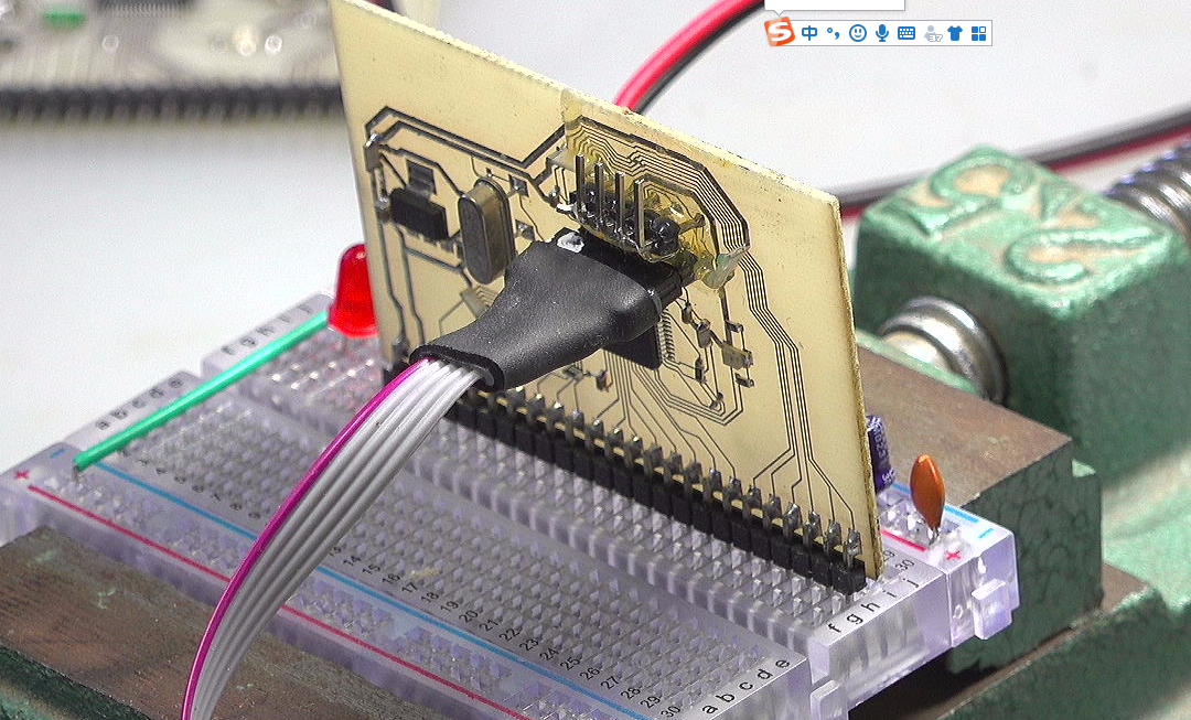
- Figure 1.2.3 mm32f3277 micro Python experimental board
- Table 1-1 MM32 PWM resource configuration
- Figure 1.2.4 output 500501hz PWM waveform at A6 and B6
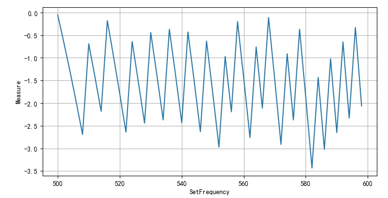
- Figure 1.2.5 difference between setting frequency and output frequency between 500-600Hz
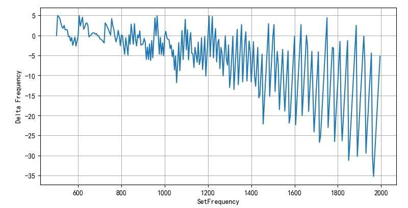
- Figure 1.2.6 frequency differences in the 500 - 2000 range
- Figure 1.2.3 DTMF frequency coding
from machine                import Pin,mem32,PWM
import utime

led = Pin('PB2', Pin.OUT_PUSHPULL)
f = 697
pwm0 = PWM(0, freq=f, duty=500)
pwm1 = PWM(4, freq=f, duty=500)

from micropython            import const
APB2PERIPH_BASE = const(0x40010000)
UART1_BASE    = const(APB2PERIPH_BASE + 0x3800)
UART1_RDR     = const(UART1_BASE + 1*4)
UART1_CSR     = const(UART1_BASE + 2*4)
REPLBUF_LENGTH = const(64)
replbuf = [0]*REPLBUF_LENGTH
replpoint = 0
def procREPL(f):
    global replbuf,replpoint
    if mem32[UART1_CSR] & 0x2:
        bc = mem32[UART1_RDR]
        if replpoint < REPLBUF_LENGTH-1:
            replbuf[replpoint] = bc
            replpoint += 1
        if bc == 13:
            f(bytes(replbuf[0:replpoint-1]))
            replpoint = 0

def f(s):
    global pwm0,pwm1
    frq= int(s)
    print(frq)
    pwm0.deinit()
    pwm1.deinit()
    pwm0 = PWM(0, freq=frq, duty=500)
    pwm1 = PWM(4, freq=frq, duty=500)

while True:
    procREPL(f)
#!/usr/local/bin/python
# -*- coding: gbk -*-
#============================================================
# TEST3.PY                     -- by Dr. ZhuoQing 2022-02-05
#
# Note:
#============================================================

from headm import *                 # =

from tsmodule.tsstm32       import *

setf = range(500, 2000, 5)
outf = []

stm32cmd('SNDCD%d\r'%setf[0])
time.sleep(2)

for f in setf:
    stm32cmd('SNDCD%d\r'%f)
    printf(f)
    time.sleep(1)
    meter = meterval()
    outf.append(meter[0])
    tspsave('measure', setf=setf, outf=outf)

delf = [f1-f2 for f1,f2 in zip(setf, outf)]
plt.plot(setf, delf)

plt.xlabel("SetFrequency")
plt.ylabel("Delta Frequency")
plt.grid(True)
plt.tight_layout()
plt.show()


printf('\a')


#------------------------------------------------------------
#        END OF FILE : TEST3.PY
#============================================================