I2C is a very common serial communication interface, which is used to connect various peripherals, sensors and other devices. It has been tested in the bare metal part
I2C interface of I.MX6U is explained in detail. In this chapter, let's learn how to develop I2C interface device driver under Linux
The focus is to learn the I2C driver framework under Linux and write I2C device drivers according to the specified framework. This chapter also uses
Take the three in one ambient light sensor AP3216C on the I.MX6U-ALPHA development board as an example and explain it through AP3216C
How to write I2C device driver under Linux.
1. Introduction to Linux I2C driver framework
Recall how we wrote the AP3216C driver in the bare metal article. We wrote four files: bsp_i2c.c,
bsp_i2c.h,bsp_ap3216c.c and bsp_ap3216c.h. The first two are IIC interface drivers of I.MX6U, and the last two are
The file is AP3216C, an I2C device driver file. Equivalent to two-part drive:
1. I2C host driver.
2. I2C device drive.
Once the I2C host driver is written, it does not need to be modified. Other I2C devices directly call the information provided by the host driver
The API function can read and write. This is just in line with the idea of driver separation and layering of Linux, so the Linux kernel will also
The I2C drive is divided into two parts:
1. I2C bus driver. I2C bus driver is the I2C controller driver of SOC, also known as I2C adapter driver.
2. I2C device driver. I2C device driver is a driver written for specific I2C devices.
1) I2C bus drive
First, let's take a look at the I2C bus. When talking about platform, we said that platform is a virtual bus, and the purpose is
It is to realize the bus, device and driver framework. For I2C, there is no need to virtualize a bus and use it directly
I2C bus is enough. I2C bus driver focuses on I2C adapter (i.e. I2C interface controller of SOC). Here
Two important data structures are used: i2c_adapter and i2c_algorithm, the Linux kernel will the I2C adapter of SOC
(controller) abstracted as i2c_adapter,i2c_ The adapter structure is defined in include / Linux / I2C H file, structure
The contents are as follows:
498 struct i2c_adapter {
499 	struct module *owner;
500 	unsigned int class; /* classes to allow probing for */
501 	const struct i2c_algorithm *algo; /* Bus access algorithm */
502 	void *algo_data;
503
504 	/* data fields that are valid for all devices */
505 	struct rt_mutex bus_lock;
506
507 	int timeout; /* in jiffies */
508 	int retries;
509 	struct device dev; /* the adapter device */
510
511 	int nr;
512 	char name[48];
513 	struct completion dev_released;
514
515 	struct mutex userspace_clients_lock;
516 	struct list_head userspace_clients;
517
518 	struct i2c_bus_recovery_info *bus_recovery_info;
519 	const struct i2c_adapter_quirks *quirks;
520 };
Line 501, I2C_ The pointer variable algo of algorithm type must provide external reading and writing for an I2C adapter
API functions. Device drivers can use these API functions to complete read and write operations. i2c_algorithm
This is the method by which the I2C adapter communicates with the IIC device.
i2c_ The algorithm structure is defined in include / Linux / I2C H file, the contents are as follows (delete conditional compilation):
391 struct i2c_algorithm {
......
398 	int (*master_xfer)(struct i2c_adapter *adap,
							struct i2c_msg *msgs,
399 						int num);
400 	int (*smbus_xfer) (struct i2c_adapter *adap, u16 addr,
401 						unsigned short flags, char read_write,
402 						u8 command, int size, union i2c_smbus_data *data);
403
404 	/* To determine what the adapter supports */
405 	u32 (*functionality) (struct i2c_adapter *);
......
411 };
Line 398, master_xfer is the transfer function of I2C adapter, which can be used to complete communication with IIC devices
Communication.
Line 400, smbus_xfer is the transfer function of SMBUS bus.
To sum up, the main work of I2C bus driver or I2C adapter driver is to initialize i2c_adapter structure
Variable, and then set I2C_ Master in algorithm_ Xfer function. Pass after completion
i2c_add_numbered_adapter or I2C_ add_ The two functions adapter register the set with the system
i2c_adapter, the prototypes of these two functions are as follows:
int i2c_add_adapter(struct i2c_adapter *adapter)
int i2c_add_numbered_adapter(struct i2c_adapter *adap)
The difference between the two functions is I2C_ add_ The adapter uses a dynamic bus number, and
i2c_add_numbered_adapter uses a static bus number.
Function parameters and return values have the following meanings:
Adapter or adap: I2C to add to the Linux kernel_ Adapter, that is, I2C adapter.
Return value: 0, successful; Negative value, failed.
Use I2C if you want to remove the I2C adapter_ del_ Just use the adapter function. The function prototype is as follows:
void i2c_del_adapter(struct i2c_adapter * adap)
Function parameters and return values have the following meanings:
adap: I2C adapter to remove.
Return value: none.
The I2C bus (controller or adapter) driver is explained here. Generally, the I2C bus driver of SOC is driven by semiconductors
For example, the I2C adapter driver NXP of I.MX6U has been written by the manufacturer. This does not need to be written by the user
Write. Therefore, I2C bus driver is shielded for SOC users. We just need to focus on I2C devices
Just drive. Unless you work in a semiconductor company, your job is to write I2C adapter driver.
2) I2C device drive
I2C device driver focuses on two data structures: i2c_client and i2c_driver, according to bus, device and drive module
The I2C bus has been described in the previous section. There are devices and drivers left, i2c_client describes the device information,
i2c_driver describes the driving content, which is similar to platform_driver.
1,i2c_client structure
i2c_ The client structure is defined in include / Linux / I2C H in the document, the contents are as follows:
217 struct i2c_client {
218 	unsigned short flags; /* sign */
219 	unsigned short addr; /* Chip address, 7 bits, low 7 bits */
......
222 	char name[I2C_NAME_SIZE]; /* name */
223 	struct i2c_adapter *adapter; /* Corresponding I2C adapter */
224 	struct device dev; /* Equipment structure */
225 	int irq; /* interrupt */
226 	struct list_head detected;
......
230 };
One device corresponds to one i2c_client, every time an I2C device is detected, it will assign one to the I2C device
i2c_client.
2,i2c_driver structure
i2c_driver is similar to platform_driver is the key content we need to deal with when writing I2C device driver,
i2c_ The driver structure is defined in include / Linux / I2C H in the document, the contents are as follows:
161 struct i2c_driver {
162 	unsigned int class;
163
164 	/* Notifies the driver that a new bus has appeared. You should
165 	* avoid using this, it will be removed in a near future.
166 	*/
167 	int (*attach_adapter)(struct i2c_adapter *) __deprecated;
168
169 	/* Standard driver model interfaces */
170 	int (*probe)(struct i2c_client *, const struct i2c_device_id *);
171 	int (*remove)(struct i2c_client *);
172
173 	/* driver model interfaces that don't relate to enumeration */
174 	void (*shutdown)(struct i2c_client *);
175
176 	/* Alert callback, for example for the SMBus alert protocol.
177 	* The format and meaning of the data value depends on the
178 	* protocol.For the SMBus alert protocol, there is a single bit
179 	* of data passed as the alert response's low bit ("event
180 	flag"). */
181 	void (*alert)(struct i2c_client *, unsigned int data);
182
183 	/* a ioctl like command that can be used to perform specific
184 	* functions with the device.
185 	*/
186 	int (*command)(struct i2c_client *client, unsigned int cmd, void *arg);
187
188 	struct device_driver driver;
189 	const struct i2c_device_id *id_table;
190
191 	/* Device detection callback for automatic device creation */
192 	int (*detect)(struct i2c_client *, struct i2c_board_info *);
193 	const unsigned short *address_list;
194 	struct list_head clients;
195 };
In line 170, after the I2C device and driver are successfully matched, the probe function will execute, just like the platform driver.
Line 188, device_driver drives the structure. If you use the device tree, you need to set device_driver's
of_match_table member variable, that is, the compatible attribute of the driver.
Line 189, id_table is a traditional device matching ID table that does not use the device tree.
For our I2C device driver writers, the key work is to build i2c_driver, which is required after the build is completed
Register this I2C with the Linux kernel_ driver. i2c_ The driver registration function is i2c_register_driver, this function
The prototype is as follows:
int i2c_register_driver(struct module *owner, struct i2c_driver *driver)
Function parameters and return values have the following meanings:
owner: This is generally used_ MODULE.
Driver: I2C to register_ driver.
Return value: 0, successful; Negative value, failed.
In addition, i2c_add_driver is also often used to register i2c_driver,i2c_add_driver is a macro defined as follows:
587 #define i2c_add_driver(driver) \
588 i2c_register_driver(THIS_MODULE, driver)
i2c_add_driver is right i2c_register_driver makes a simple package with only one parameter, that is
I2C to register_ driver. When you log off the I2C device driver, you need to register the I2C previously_ Driver from within Linux
Log out of the core and use i2c_del_driver function. The prototype of this function is as follows:
void i2c_del_driver(struct i2c_driver *driver)
Function parameters and return values have the following meanings:
Driver: I2C to log off_ driver.
Return value: none.
i2c_ The registration example code of driver is as follows:
1 /* i2c Driven probe function */
2 static int xxx_probe(struct i2c_client *client,const struct i2c_device_id *id)
3 {
4 	/* Function specific program */
5 	return 0;
6 }
7
8 /* i2c Driven remove function */
9 static int ap3216c_remove(struct i2c_client *client)
10 {
11 	/* Function specific program */
12 	return 0;
13 }
14
15 /* Traditional matching method ID list */
16 static const struct i2c_device_id xxx_id[] = {
17 	{"xxx", 0},
18 	{}
19 };
20
21 /* Device tree matching list */
22 static const struct of_device_id xxx_of_match[] = {
23 	{ .compatible = "xxx" },
24 	{ /* Sentinel */ }
25 };
26
27 /* i2c Drive structure */
28 static struct i2c_driver xxx_driver = {
29 	.probe = xxx_probe,
30 	.remove = xxx_remove,
31 	.driver = {
32 		.owner = THIS_MODULE,
33 		.name = "xxx",
34 		.of_match_table = xxx_of_match,
35 	},
36 	.id_table = xxx_id,
37 };
38
39 /* Drive entry function */
40 static int __init xxx_init(void)
41 {
42 	int ret = 0;
43
44 	ret = i2c_add_driver(&xxx_driver);
45 	return ret;
46 }
47
48 /* Drive exit function */
49 static void __exit xxx_exit(void)
50 {
51 	i2c_del_driver(&xxx_driver);
52 }
53
54 module_init(xxx_init);
55 module_exit(xxx_exit);
Lines 16-19, i2c_device_id, which matches the ID table when there is no device tree.
Lines 22-25, of_device_id, the matching table used by the device tree.
Lines 28-37, i2c_driver, after the I2C device and I2C driver are successfully matched, the probe function will execute, which
Like platform drivers, the probe function is basically a standard character device driver
A set.
3) I2C equipment and drive matching process
The matching process between I2C device and driver is completed by I2C core, drivers / I2C / I2C core C is the core of I2C
The I2C core provides some API functions independent of specific hardware, such as those mentioned earlier:
1,i2c_adapter register / unregister function
i2c_add_adapter(struct i2c_adapter *adapter)
i2c_add_numbered_adapter(struct i2c_adapter *adap)
i2c_del_adapter(struct i2c_adapter *adap)
2,i2c_driver registration / logoff function
i2c_register_driver(struct module *owner,struct i2c_driver *driver)
i2c_add_driver(struct i2c_driver *driver)
i2c_del_driver(structi2c_driver*driver)
The matching process between device and driver is also completed by I2C bus. The data structure of I2C bus is i2c_bus_type, definition
At drivers / I2C / I2C core C file, I2C_ bus_ The content of type is as follows:
736 struct bus_type i2c_bus_type = {
737 	.name = "i2c",
738 	.match = i2c_device_match,
739 	.probe = i2c_device_probe,
740 	.remove = i2c_device_remove,
741 	.shutdown = i2c_device_shutdown,
742 };
. match is the device and driver matching function of I2C bus, here is i2c_device_match this function, this
The function contents are as follows:
457 static int i2c_device_match(struct device *dev, struct device_driver *drv)
458 {
459 	struct i2c_client *client = i2c_verify_client(dev);
460 	struct i2c_driver *driver;
461
462 	if (!client)
463 		return 0;
464
465 	/* Attempt an OF style match */
466 	if (of_driver_match_device(dev, drv))
467 		return 1;
468
469 	/* Then ACPI style match */
470 	if (acpi_driver_match_device(dev, drv))
471 		return 1;
472
473 	driver = to_i2c_driver(drv);
474 	/* match on an id table if there is one */
475 	if (driver->id_table)
476 		return i2c_match_id(driver->id_table, client) != NULL;
477
478 	return 0;
479 }
Line 466, of_ driver_ match_ The device function is used to complete the device tree device and driver matching. Compare I2C device section
Compatible attribute and of of of points_ device_ Whether the compatible attribute in ID is equal. If it is equivalent
This means that the I2C device and driver match.
Line 470, ACPI_ driver_ match_ The device function is used for matching in ACPI form.
Line 476, I2C_ match_ The ID function is used for the traditional I2C device and driver matching process without device tree. Compare I2C
Device name and I2C_ device_ Whether the name field of ID is equal. If it is equal, it indicates that I2C device and driver
Dynamic matching.
2.I2C device driver writing process
The I2C adapter driver SOC manufacturer has written it for us. What we need to do is to write a specific device driver
In this section, we will learn the detailed writing process of I2C device driver.
1) I2C equipment information description
1. When the device tree is not used
First of all, it is necessary to describe the I2C device node information. First, let's take a look at how it is in the BSP when the device tree is not used
The interface describes the I2C device information. When the device tree is not used, I2C needs to be used in the BSP_ board_ Info knot
Construct to describe a specific I2C device. i2c_ board_ The info structure is as follows:
295 struct i2c_board_info {
296 	char type[I2C_NAME_SIZE]; /* I2C Device name */
297 	unsigned short flags; /* sign */
298 	unsigned short addr; /* I2C Device address */
299 	void *platform_data;
300 	struct dev_archdata *archdata;
301 	struct device_node *of_node;
302 	struct fwnode_handle *fwnode;
303 	int irq;
304 };
Two member variables, type and addr, must be set. One is the name of the I2C device and the other is the I2C device
Device address. Open arch / arm / Mach IMX / Mach mx27_ 3ds. C file, which is about
The I2C device information of OV2640 is described as follows:
392 static struct i2c_board_info mx27_3ds_i2c_camera = {
393 	I2C_BOARD_INFO("ov2640", 0x30),
394 };
I2C is used in the above code_ BOARD_ Info to complete mx27_3ds_i2c_camera initialization,
I2C_BOARD_INFO is a macro, which is defined as follows:
316 #define I2C_BOARD_INFO(dev_type, dev_addr) \
317 .type = dev_type, .addr = (dev_addr)
It can be seen that I2C_ BOARD_ Info macro is actually setting I2C_ board_ Info type and addr are two components
Therefore, the main work of the above code is to set the device ground with the name of I2C device ov2640 and ov2640
The address is 0X30.
You can search I2C globally in the Linux source code_ board_ Info, you will find a lot to i2c_board_info definition
I2C device information, which is the description method of I2C device when the device tree is not used. When the device tree is used
I'll never use I2C again_ board_ Info to describe the I2C device.
2. When using the device tree
When using the device tree, I2C device information can be created by creating corresponding nodes, such as the official EVK of NXP
The hair board is connected to the magnetometer chip mag3110 on i2c1, so the mag3110 child must be created under the i2c1 node
Node, and then describe the relevant information of mag3110 chip in this sub node. Open imx6ull-14x14-
evk.dts this device tree file, and then find the following contents:
1 &i2c1 {
2 		clock-frequency = <100000>;
3 		pinctrl-names = "default";
4 		pinctrl-0 = <&pinctrl_i2c1>;
5 		status = "okay";
6
7 		mag3110@0e {
8 			compatible = "fsl,mag3110";
9 			reg = <0x0e>;
10 			position = <2>;
11 		};
......
20 };
Lines 7-11, add mag3110 child node to i2c1, line 7“ mag3110@0e ”Is the child node name, after "@"
Face "0e" is the I2C device address of mag3110. Line 8 sets the compatible property value to
“fsl,mag3110”. The reg attribute in line 9 also sets the device address of mag3110, so the value
Is 0x0e.
The creation of I2C device node focuses on the setting of compatible attribute and reg attribute, one for matching driver and the other
One is used to set the device address.
2) I2C equipment data transceiver processing flow
As mentioned earlier, the first thing for I2C device driver is to initialize i2c_driver and register with the Linux kernel.
When the device and driver match I2C_ The probe function in the driver will execute, and what is done in the probe function is
The character device driver. Generally, you need to initialize the I2C device in the probe function. To initialize the I2C device, you need to
It must be able to read and write I2C device registers, and I2C is used here_ The transfer function.
i2c_ The transfer function will eventually call I2C in the I2C adapter_ Master in algorithm_ Xfer function, for
I.MX6U is i2c_imx_xfer this function. i2c_ The prototype of transfer function is as follows:
int i2c_transfer(struct i2c_adapter *adap,
struct i2c_msg *msgs,
int num)
Function parameters and return values have the following meanings:
adap: I2C adapter used, I2C_ The client saves its corresponding i2c_adapter.
msgs: one or more messages to be sent by I2C.
num: the number of messages, that is, the number of msgs.
Return value: negative value, failure, other non negative values, number of msgs sent.
Let's focus on the parameter msgs, which is an i2c_msg type pointer parameter, I2C for data sending and receiving
To put it bluntly, it is message transmission. The Linux kernel uses i2c_msg structure to describe a message. i2c_msg structure
Defined in include / UAPI / Linux / I2C H file, the structure is as follows:
68 struct i2c_msg {
69 	__u16 addr; /* Slave address */
70 	__u16 flags; /* sign */
71 	#define I2C_M_TEN 0x0010
72 	#define I2C_M_RD 0x0001
73 	#define I2C_M_STOP 0x8000
74 	#define I2C_M_NOSTART 0x4000
75 	#define I2C_M_REV_DIR_ADDR 0x2000
76 	#define I2C_M_IGNORE_NAK 0x1000
77 	#define I2C_M_NO_RD_ACK 0x0800
78 	#define I2C_M_RECV_LEN 0x0400
79 	__u16 len; /* Message (msg) length */
80 	__u8 *buf; /* Message data */
81 };
Using I2C_ The transfer function should construct I2C before sending data_ MSG, using i2c_transfer to receive I2C data
The example code of the message is as follows:
1 /* Equipment structure */
2 struct xxx_dev {
3 	......
4 	void *private_data; /* Private data, usually set to i2c_client */
5 };
6
7 /*
8 * @description : Read multiple register data of I2C device
9 * @param – dev : I2C equipment
10 * @param – reg : First register address to read
11 * @param – val : Read data
12 * @param – len : Length of data to read
13 * @return : Operation results
14 */
15 static int xxx_read_regs(struct xxx_dev *dev, u8 reg, void *val, int len)
16 {
17 	int ret;
18 	struct i2c_msg msg[2];
19 	struct i2c_client *client = (struct i2c_client *) dev->private_data;
20
21 	/* msg[0],The first write message sends the first address of the register to be read */
22 	msg[0].addr = client->addr; /* I2C Device address */
23 	msg[0].flags = 0; /* Mark as send data */
24 	msg[0].buf = ® /* First address read */
25 	msg[0].len = 1; /* reg length */
26
27 	/* msg[1],The second read message reads the register data */
28 	msg[1].addr = client->addr; /* I2C Device address */
29 	sg[1].flags = I2C_M_RD; /* Mark as read data */
30 	msg[1].buf = val; /* Read data buffer */
31 	msg[1].len = len; /* Length of data to read */
32
33 	ret = i2c_transfer(client->adapter, msg, 2);
34 	if(ret == 2) {
35 		ret = 0;
36 	} else {
37 		ret = -EREMOTEIO;
38 	}
39 	return ret;
40 }
41
42 /*
43 * @description : Write data to multiple registers of I2C device
44 * @param – dev : Device structure to write
45 * @param – reg : First address of register to be written
46 * @param – val : Data buffer to write to
47 * @param – len : Length of data to write
48 * @return : Operation results
49 */
50 static s32 xxx_write_regs(struct xxx_dev *dev, u8 reg, u8 *buf, u8 len)
51 {
52 	u8 b[256];
53 	struct i2c_msg msg;
54 	struct i2c_client *client = (struct i2c_client *)dev->private_data;
55
56 	b[0] = reg; /* Register header address */
57 	memcpy(&b[1],buf,len); /* Copy the data to be sent to array b */
58
59 	msg.addr = client->addr; /* I2C Device address */
60 	msg.flags = 0; /* Mark as write data */
61
62 	msg.buf = b; /* Data buffer to send */
63 	msg.len = len + 1; /* Length of data to send */
64
65 	return i2c_transfer(client->adapter, &msg, 1);
66 }
Lines 2 to 5, the device structure, add a pointer member variable that executes void to the device structure
private_data, this member variable is used to save the private data of the device. In I2C device driver, we have one
Generally, point it to the I2C corresponding to the I2C device_ client.
Lines 15-40, XXX_ read_ The regs function is used to read multiple register data of I2C device. Line 18 defines a
i2c_msg array, two array elements, because I2C sends the data to be read first when reading data
Memory address, and then read the data, so you need to prepare two i2c_msg. One for sending deposit
The address of the register, which is used to read the value of the register. For msg[0], set flags to 0, indicating the number of writes
According to. addr of msg[0] is the device address of I2C device, and the buf member variable of msg[0] is to be read
Register address. For msg[1], set flags to I2C_M_RD, read data.
The buf member variable of msg[1] is used to save the read data, and the len member variable is the data to be read
Length. Call I2C_ The transfer function completes the I2C data reading operation.
Lines 50-66, XXX_ write_ The regs function is used to write data to multiple registers of I2C device. I2C write operation is better than read operation
Make it simple, so an i2c_msg is enough. Array b is used to store the first address of the register and the address to be sent
In line 59, set the addr of msg as the I2C device address. In line 60, set the flags of msg to
0, that is, write data. Line 62 sets the data to be sent, that is, array b. Line 63 setting
The len of msg is len+1 because a register address of one byte is added. Finally passed
i2c_ The transfer function completes the write operation to the I2C device.
In addition, there are two API functions for I2C data sending and receiving, which will eventually be called
i2c_transfer. Let's first look at the I2C data sending function I2C_ master_ The prototype of send function is as follows:
int i2c_master_send(const struct i2c_client *client,
const char *buf,
int count)
Function parameters and return values have the following meanings:
Client: I2C corresponding to I2C device_ client.
buf: data to be sent.
count: the number of data bytes to be sent. It should be less than 64KB, which is I2C_ The len member variable of MSG is a U16 (none)
Data of symbol (16 bit) type.
Return value: negative value, failure, other non negative values, number of bytes sent.
The I2C data receiving function is i2c_master_recv, the function prototype is as follows:
int i2c_master_recv(const struct i2c_client *client,
char *buf,
int count)
Function parameters and return values have the following meanings:
Client: I2C corresponding to I2C device_ client.
buf: data to be received.
count: the number of data bytes to be received. It should be less than 64KB, which is I2C_ The len member variable of MSG is a U16 (null)
No. (16 bit) type of data.
Return value: negative value, failure, other non negative values, number of bytes sent.
That's all for the writing process of I2C device driver under Linux, with the focus on I2C_ Construction and application of MSG
i2c_ Call the transfer function. Next, we will write the Linux driver of AP3216C, an I2C device.
3. Preparation of experimental program
1) modify the equipment tree
1. IO modification or addition
First of all, the IO must be modified. The AP3216C uses the I2C1 interface and the I2C1 interface on the I.MX6U-ALPHA development board
Uart4 port is used_ TXD and UART4_RXD, so these two IO S must be set in the device tree. as
If you want to use the interrupt function of AP3216C, you also need to initialize the AP_ Gio1 corresponding to int_ Io01 this IO,
In this chapter, we do not use interrupt function. Therefore, only uart4 needs to be set_ TXD and UART4_RXD these two
IO, NXP has actually set these two IOS. Open imx6ull alientek EMMC DTS, and then find
The following:
1 pinctrl_i2c1: i2c1grp {
2     fsl,pins = <
3         MX6UL_PAD_UART4_TX_DATA__I2C1_SCL 0x4001b8b0
4         MX6UL_PAD_UART4_RX_DATA__I2C1_SDA 0x4001b8b0
5     >;
6 };
pinctrl_i2c1 is the IO node of I2C1. Uart4 will be used here_ TXD and UART4_RXD these two IOS are multiplexed respectively
I2C1_SCL and I2C1_SDA and electrical properties are set to 0x4001b8b0.
2. Add ap3216c child node in i2c1 node
ap3216c is connected to i2c1, so you need to add the device child node of ap3216c under i2c1 node
imx6ull-alientek-emmc. i2c1 node is found in DTS file. The default content of this node is as follows:
1 &i2c1 {
2 	clock-frequency = <100000>;
3 	pinctrl-names = "default";
4 	pinctrl-0 = <&pinctrl_i2c1>;
5 	status = "okay";
6
7 	mag3110@0e {
8 		compatible = "fsl,mag3110";
9 		reg = <0x0e>;
10 		position = <2>;
11 	};
12
13 	fxls8471@1e {
14 		compatible = "fsl,fxls8471";
15 		reg = <0x1e>;
16 		position = <0>;
17 		interrupt-parent = <&gpio5>;
18 		interrupts = <0 8>;
19 	};
20 };
In line 2, the clock frequency attribute is I2C frequency, which is set to 100KHz here.
In line 4, the pinctrl-0 attribute specifies that the IO used by I2C is pinctrl in the above code_ I2c1 child node.
In lines 7 to 11, mag3110 is a magnetometer. The official EVK development board of NXP is connected with mag3110, so NXP
Add the child node mag3110 under the i2c1 node. I.MX6U-ALPHA on of punctual atoms
mag3110 is not used on the board, so this node needs to be deleted.
In lines 13-19, the NXP official EVK development board is also connected with a fxls8471, and the I.MX6U-ALPHA of punctual atom is turned on
The hair board also does not have this device, so it should also be deleted.
Delete the original two I2C child nodes mag3110 and fxls8471 in the i2c1 node, and then add ap3216c
Child node information. The i2c1 node content after completion is as follows:
1 &i2c1 {
2 	clock-frequency = <100000>;
3 	pinctrl-names = "default";
4 	pinctrl-0 = <&pinctrl_i2c1>;
5 	status = "okay";
6
7 	ap3216c@1e {
8 		compatible = "alientek,ap3216c";
9 		reg = <0x1e>;
10 	};
11 };
Line 7, ap3216c child node, "1e" after @ is the device address of ap3216c.
In line 8, set the compatible value to "alientek,ap3216c".
In line 9, the reg attribute also sets the ap3216c device address, so reg is set to 0x1e.
After modifying the device tree, recompile it with "make dtbs", and then start Linux with the new device tree
Kernel/ All I2C devices are stored in the sys/bus/i2c/devices directory. If the device tree is modified correctly, it will be deleted
See a subdirectory named "0-001e" under / sys/bus/i2c/devices, as shown in Figure 1:

Figure 1. Current system I2C equipment
"0-001e" in Figure 1 is the device directory of ap3216c, and "1E" is the device address of ap3216c. Enter 0-001e
Directory, you can see the "name" file. Name saves the name of the device when asking for a price. Here it is
"ap3216c", as shown in Figure 2:
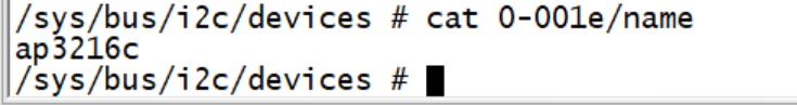
Figure 2. ap3216c device name