catalogue
1. Introduction to Linux kernel RTC driver
2.I. Analysis of mx6u internal RTC driver
3.RTC time viewing and setting
RTC is a real-time clock, which is used to record the current system time. For Linux system, time is very important, just like me
Just as we use Windows computers or mobile phones to check time, we also need to check time when using Linux devices. This chapter
Let's learn how to write RTC driver under Linux.
1. Introduction to Linux kernel RTC driver
RTC device driver is a standard character device driver. The application program passes open, release, read, write and ioctl
Function to complete the operation of RTC equipment. We have discussed the RTC hardware principle in Chapter 25 of bare metal
Detailed explanation.
The Linux kernel abstracts RTC devices as rtc_device structure, so RTC device driver is to apply for and initialize
rtc_device, and finally rtc_device is registered in the Linux kernel, so that the Linux kernel has an RTC device. to
The operation of RTC equipment must be represented by an operation set (structure). Let's take a look at RTC first_ Device structure
Body, which is defined in include / Linux / RTC In the H file, the structure is as follows (delete conditional compilation):
104 struct rtc_device
105 {
106 	struct device dev; /* equipment */
107 	struct module *owner;
108
109 	int id; /* ID */
110 	char name[RTC_DEVICE_NAME_SIZE]; /* name */
111
112 	const struct rtc_class_ops *ops; /* RTC Device underlying operation function */
113 	struct mutex ops_lock;
114
115 	struct cdev char_dev; /* Character device */
116 	unsigned long flags;
117
118 	unsigned long irq_data;
119 	spinlock_t irq_lock;
120 	wait_queue_head_t irq_queue;
121 	struct fasync_struct *async_queue;
122
123 	struct rtc_task *irq_task;
124 	spinlock_t irq_task_lock;
125 	int irq_freq;
126 	int max_user_freq;
127
128 	struct timerqueue_head timerqueue;
129 	struct rtc_timer aie_timer;
130 	struct rtc_timer uie_rtctimer;
131 	struct hrtimer pie_timer; /* sub second exp, so needs hrtimer */
132 	int pie_enabled;
133 	struct work_struct irqwork;
134 	/* Some hardware can't support UIE mode */
135 	int uie_unsupported;
......
147 };
We need to focus on the OPS member variable, which is an RTC_ class_ Pointer variable of OPS type, rtc_class_ops
It is the lowest level operation function set of RTC device, including reading time from RTC device and writing new time value to RTC device
Wait. Therefore, rtc_class_ops needs to be written by the user according to the RTC equipment used. This structure is defined in
include/linux/rtc.h in the document, the contents are as follows:
71 struct rtc_class_ops {
72 	int (*open)(struct device *);
73 	void (*release)(struct device *);
74 	int (*ioctl)(struct device *, unsigned int, unsigned long);
75 	int (*read_time)(struct device *, struct rtc_time *);
76 	int (*set_time)(struct device *, struct rtc_time *);
77 	int (*read_alarm)(struct device *, struct rtc_wkalrm *);
78 	int (*set_alarm)(struct device *, struct rtc_wkalrm *);
79 	int (*proc)(struct device *, struct seq_file *);
80 	int (*set_mmss64)(struct device *, time64_t secs);
81	int (*set_mmss)(struct device *, unsigned long secs);
82 	int (*read_callback)(struct device *, int data);
83 	int (*alarm_irq_enable)(struct device *, unsigned int enabled);
84 };
Just look at the name RTC_ class_ What do these functions in the OPS operation set do, but we should pay attention to,
rtc_ class_ These functions in OPs are only the lowest RTC device operation functions, not provided to the application layer
file_ The operations function sets the operations. RTC is a character device, so there must be a file of the character device_ Operations function
The Linux kernel provides a rtc universal character device driver file named drivers / rtc / rtc dev.c, rtc-
The dev.c file provides a file shared by all RTC devices_ The operations function sets the operations as follows:
448 static const struct file_operations rtc_dev_fops = {
449 	.owner = THIS_MODULE,
450 	.llseek = no_llseek,
451 	.read = rtc_dev_read,
452 	.poll = rtc_dev_poll,
453 	.unlocked_ioctl = rtc_dev_ioctl,
454 	.open = rtc_dev_open,
455 	.release = rtc_dev_release,
456 	.fasync = rtc_dev_fasync,
457 };
Are you familiar with the above code? The standard character device operation set. The application can set / read through the ioctl function
Take the time and set / read the alarm clock, then the corresponding RTC_ dev_ The IOCTL function will execute, rtc_dev_ioctl will eventually
By operating RTC_ class_ Read in Ops_ time,set_time and other functions to read and write to specific RTC devices. We Jane
Just look at rtc_dev_ioctl function, the function contents are as follows (omitted):
218 static long rtc_dev_ioctl(struct file *file,
219 unsigned int cmd, unsigned long arg)
220 {
221 	int err = 0;
222 	struct rtc_device *rtc = file->private_data;
223 	const struct rtc_class_ops *ops = rtc->ops;
224 	struct rtc_time tm;
225 	struct rtc_wkalrm alarm;
226 	void __user *uarg = (void __user *) arg;
227
228 	err = mutex_lock_interruptible(&rtc->ops_lock);
229 	if (err)
230 		return err;
......
269 	switch (cmd) {
......
333 		case RTC_RD_TIME: /* Read time */
334 			mutex_unlock(&rtc->ops_lock);
335
336				 err = rtc_read_time(rtc, &tm);
337 			if (err < 0)
338 				return err;
339
340 			if (copy_to_user(uarg, &tm, sizeof(tm)))
341		 			err = -EFAULT;
342 			return err;
343
344 		case RTC_SET_TIME: /* Set time */
345 			mutex_unlock(&rtc->ops_lock);
346
347 			if (copy_from_user(&tm, uarg, sizeof(tm)))
348 				return -EFAULT;
349
350 			return rtc_set_time(rtc, &tm);
......
401 		default:
402 			/* Finally try the driver's ioctl interface */
403 			if (ops->ioctl) {
404 				err = ops->ioctl(rtc->dev.parent, cmd, arg);
405 				if (err == -ENOIOCTLCMD)
406 					err = -ENOTTY;
407 			} else
408 				err = -ENOTTY;
409 			break;
410 	}
411
412 	done:
413 	mutex_unlock(&rtc->ops_lock);
414 	return err;
415 }
Line 333, RTC_RD_TIME is the time read command.
Line 336, call RTC if it is the read time command_ read_ The time function obtains the current RTC clock,
rtc_read_time function, rtc_read_time will call__ rtc_read_time function__ rtc_read_time letter
The number is as follows:
23 static int __rtc_read_time(struct rtc_device *rtc,
struct rtc_time *tm)
24 {
25 	int err;
26 	if (!rtc->ops)
27 		err = -ENODEV;
28 	else if (!rtc->ops->read_time)
29 		err = -EINVAL;
30 	else {
31 		memset(tm, 0, sizeof(struct rtc_time));
32 		err = rtc->ops->read_time(rtc->dev.parent, tm);
33 		if (err < 0) {
34 			dev_dbg(&rtc->dev, "read_time: fail to read: %d\n",
35 				err);
36 			return err;
37 		}
38
39 	err = rtc_valid_tm(tm);
40 	if (err < 0)
41 		dev_dbg(&rtc->dev, "read_time: rtc_time isn't valid\n");
42 	}
43 	return err;
44 }
As can be seen from the 32 lines in the above code__ rtc_ read_ The time function calls RTC_ class_ Read in Ops_ time
To get the current time from the RTC device. rtc_ dev_ The IOCTL function handles other commands similarly, such as
RTC_ ALM_ The read command passes through RTC_ read_ The alarm function obtains the alarm value, and RTC_ read_ The alarm function passes through the layer
Layer call, and eventually RTC will be called_ class_ Read in Ops_ Alarm function to get the alarm value. So far, the Linux kernel
The RTC driver call process is very clear, as shown in Figure 1:
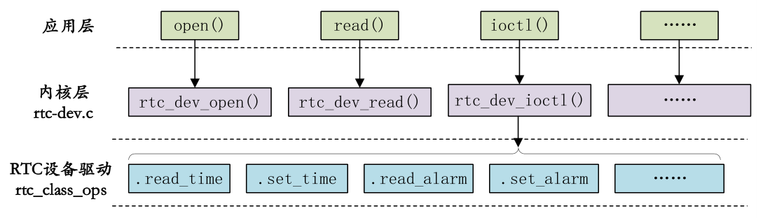
Figure 1. Linux RTC driver calling process
When RTC_ class_ After OPS is ready, it needs to be registered in the Linux kernel, which we can use here
rtc_device_ The register function completes the registration. This function requests an rtc_device and initialize this
rtc_device, and finally return the RTC to the caller_ Device, the prototype of this function is as follows:
struct rtc_device *rtc_device_register(const char *name,
struct device *dev,
const struct rtc_class_ops *ops,
struct module *owner)
Function parameters and return values have the following meanings:
Name: device name.
dev: device.
ops: RTC underlying driver function set.
Owner: driver module owner.
Return value: RTC will be returned if the registration is successful_ Device, a negative value will be returned in case of error.
RTC needs to be called when unloading the RTC driver_ device_ Unregister function to unregister the registered rtc_device, original function
The types are as follows:
void rtc_device_unregister(struct rtc_device *rtc)
Function parameters and return values have the following meanings:
rtc: the rtc to delete_ device.
Return value: none.
There is another pair of RTCs_ Device register function devm_rtc_device_register and devm_rtc_device_unregister,
Register and unregister RTC respectively_ device.
2.I. Analysis of mx6u internal RTC driver
First of all, let's tell you directly that we don't have to write the RTC driver of I.MX6U, because NXP has been written. In fact, for most
In terms of SOC, we don't need to write internal RTC drivers. Semiconductor manufacturers will write them well. But that doesn't mean we
I'm lazy. Although we don't need to write RTC drivers, we have to see how these original factories write RTC drivers. analysis
Driver, start with the device tree and open imx6ull Dtsi, find the following snvs in it_ RTC equipment node. The node contents are as follows:
As shown in:
1 snvs_rtc: snvs-rtc-lp {
2 	compatible = "fsl,sec-v4.0-mon-rtc-lp";
3 	regmap = <&snvs>;
4 	offset = <0x34>;
5 	interrupts = <GIC_SPI 19 IRQ_TYPE_LEVEL_HIGH>, <GIC_SPI 20 IRQ_TYPE_LEVEL_HIGH>;
6 };
In line 2, set the compatible attribute to "fsl,sec-v4.0-mon-rtc-lp", so search the Linux kernel source code for this attribute
String to find the corresponding driver file, which is drivers / RTC / RTC snvs c. In RTC snvs C the following is found in the file
Contents shown:
380 static const struct of_device_id snvs_dt_ids[] = {
381 	{ .compatible = "fsl,sec-v4.0-mon-rtc-lp", },
382 	{ /* sentinel */ }
383 };
384 MODULE_DEVICE_TABLE(of, snvs_dt_ids);
385
386 static struct platform_driver snvs_rtc_driver = {
387 	.driver = {
388 	.name = "snvs_rtc",
389 	.pm = SNVS_RTC_PM_OPS,
390 	.of_match_table = snvs_dt_ids,
391 	},
392 	.probe = snvs_rtc_probe,
393 };
394 module_platform_driver(snvs_rtc_driver);
Lines 380-383, the device tree ID table, has a compatible attribute with the value "fsl,sec-v4.0-mon-rtc-lp", so
imx6ull. Snvs in dtsi_ The RTC device node will match this driver.
Lines 386 ~ 393, the standard platform driver framework, snvs after the device and driver are successfully matched_ rtc_ The probe function will
Execution. Let's take a look at snvs_rtc_probe function, the function contents are as follows (omitted):
238 static int snvs_rtc_probe(struct platform_device *pdev)
239 {
240 	struct snvs_rtc_data *data;
241 	struct resource *res;
242 	int ret;
243 	void __iomem *mmio;
244
245 	data = devm_kzalloc(&pdev->dev, sizeof(*data), GFP_KERNEL);
246 	if (!data)
247 		return -ENOMEM;
248
249 	data->regmap = syscon_regmap_lookup_by_phandle(pdev->dev.of_node, "regmap");
250
251 	if (IS_ERR(data->regmap)) {
252 		dev_warn(&pdev->dev, "snvs rtc: you use old dts file,please update it\n");
253 		res = platform_get_resource(pdev, IORESOURCE_MEM, 0);
254
255 		mmio = devm_ioremap_resource(&pdev->dev, res);
256 		if (IS_ERR(mmio))
257 			return PTR_ERR(mmio);
258
259 		data->regmap = devm_regmap_init_mmio(&pdev->dev, mmio, &snvs_rtc_config);
260 	} else {
261 		data->offset = SNVS_LPREGISTER_OFFSET;
262 		of_property_read_u32(pdev->dev.of_node, "offset",&data->offset);
263 	}
264
265 	if (!data->regmap) {
266 		dev_err(&pdev->dev, "Can't find snvs syscon\n");
267 		return -ENODEV;
268 	}
269
270 	data->irq = platform_get_irq(pdev, 0);
271 	if (data->irq < 0)
272 		return data->irq;
......
285
286 	platform_set_drvdata(pdev, data);
287
288 	/* Initialize glitch detect */
289 	regmap_write(data->regmap, data->offset + SNVS_LPPGDR,SNVS_LPPGDR_INIT);
290
291 	/* Clear interrupt status */
292 	regmap_write(data->regmap, data->offset + SNVS_LPSR,0xffffffff);
293
294 	/* Enable RTC */
295 	snvs_rtc_enable(data, true);
296
297 	device_init_wakeup(&pdev->dev, true);
298
299 	ret = devm_request_irq(&pdev->dev, data->irq, snvs_rtc_irq_handler,
300 							IRQF_SHARED, "rtc alarm", &pdev->dev);
301 	if (ret) {
302 		dev_err(&pdev->dev, "failed to request irq %d: %d\n",
303 					data->irq, ret);
304 		goto error_rtc_device_register;
305 	}
306
307 	data->rtc = devm_rtc_device_register(&pdev->dev, pdev->name,
308 					&snvs_rtc_ops, THIS_MODULE);
309 	if (IS_ERR(data->rtc)) {
310 		ret = PTR_ERR(data->rtc);
311 		dev_err(&pdev->dev, "failed to register rtc: %d\n", ret);
312 		goto error_rtc_device_register;
313 	}
314
315 	return 0;
316
317 	error_rtc_device_register:
318 	if (data->clk)
319 		clk_disable_unprepare(data->clk);
320
321 	return ret;
322 }
Line 253, call platform_ get_ The resource function obtains the RTC peripheral register base address from the device tree.
Line 255, call the function devm_ioremap_resource completes memory mapping and obtains the physical base address of RTC peripheral register
The corresponding virtual address.
Line 259, Linux 3 1 introduces a new regmap mechanism, which is used to provide a set of convenient API functions to operate
As the underlying hardware register to improve the reusability of the code. snvs-rtc. The C file will be read using the regmap mechanism
Write the RTC underlying hardware register. Devm is used here_ regmap_ init_ The mmio function registers the hardware of RTC
The register is converted to the form of regmap, which is the regmap of the regmap mechanism_ write,regmap_read and other API functions
To manipulate registers.
Line 270, get the interrupt number of RTC from the device tree.
Line 289, set RTC_ The value of lppgdr register is SNVS_LPPGDR_INIT=0x41736166, which is used here
Regmap of regmap mechanism_ The write function writes to the register.
Line 292, set RTC_LPSR register, write 0xffffffff, LPSR is RTC status register, write 1 to clear, so this
The next step is to clear the LPSR register.
Line 295, call snvs_ rtc_ The enable function enables RTC, which sets RTC_LPCR register.
Line 299, call devm_request_irq function requests RTC interrupt, and the interrupt service function is snvs_rtc_irq_handler,
Used for RTC alarm clock interrupt.
Line 307, call devm_ rtc_ device_ The register function registers RTC with the system_ Devcie, RTC bottom driver set is
snvs_rtc_ops.
snvs_rtc_ops operation set includes functions such as reading / setting RTC time, reading / setting alarm clock, etc. snvs_rtc_ops content, such as
Below:
200 static const struct rtc_class_ops snvs_rtc_ops = {
201 	.read_time = snvs_rtc_read_time,
202 	.set_time = snvs_rtc_set_time,
203 	.read_alarm = snvs_rtc_read_alarm,
204 	.set_alarm = snvs_rtc_set_alarm,
205 	.alarm_irq_enable = snvs_rtc_alarm_irq_enable,
206 };
Let's take snvs in line 201_ rtc_ read_ Take the time function as an example to explain RTC_ class_ Various RTC underlying operations of OPS
How to write functions. snvs_ rtc_ read_ The time function is used to read the RTC time value. The contents of this function are as follows:
126 static int snvs_rtc_read_time(struct device *dev, struct rtc_time *tm)
127 {
128 	struct snvs_rtc_data *data = dev_get_drvdata(dev);
129 	unsigned long time = rtc_read_lp_counter(data);
130
131 	rtc_time_to_tm(time, tm);
132
133 	return 0;
134 }
Line 129, call rtc_read_lp_counter gets the RTC count value, which is the number of seconds.
Line 131, call rtc_time_ to_ The TM function converts the obtained seconds into a time value, that is, rtc_time struct class
Type, RTC_ The time structure is defined as follows:
20 struct rtc_time {
21 	int tm_sec;
22 	int tm_min;
23 	int tm_hour;
24 	int tm_mday;
25 	int tm_mon;
26 	int tm_year;
27 	int tm_wday;
28 	int tm_yday;
29 	int tm_isdst;
30 };
Finally, let's look at rtc_read_lp_counter function. This function is used to read the RTC count value. The contents of the function are as follows (with saving)
(omitted):
50 static u32 rtc_read_lp_counter(struct snvs_rtc_data *data)
51 {
52 	u64 read1, read2;
53 	u32 val;
54
55 	do {
56 		regmap_read(data->regmap, data->offset + SNVS_LPSRTCMR,&val);
57 		read1 = val;
58 		read1 <<= 32;
59 		regmap_read(data->regmap, data->offset + SNVS_LPSRTCLR,&val);
60 		read1 |= val;
61
62 		regmap_read(data->regmap, data->offset + SNVS_LPSRTCMR,&val);
63 		read2 = val;
64 		read2 <<= 32;
65 		regmap_read(data->regmap, data->offset + SNVS_LPSRTCLR,&val);
66 		read2 |= val;
67 		/*
68 		* when CPU/BUS are running at low speed, there is chance that
69 		* we never get same value during two consecutive read, so here
70 		* we only compare the second value.
71 		*/
72 	} while ((read1 >> CNTR_TO_SECS_SH) != (read2 >>CNTR_TO_SECS_SH));
73
74 	/* Convert 47-bit counter to 32-bit raw second count */
75 	return (u32) (read1 >> CNTR_TO_SECS_SH);
76 }
Lines 56-72, read RTC_LPSRTCMR and RTC_LPSRTCLR these two registers to obtain the count value of RTC,
The unit is seconds, which is the current time. Here, the RTC count value is read twice because it needs to be read twice
Therefore, the time data may be updated when reading the second register, resulting in time uncertainty
Match, so it is read twice continuously here. If the time values of the two times are equal, it means that the time data is valid.
Line 75, return the time value. Note that the RTC count value read earlier is shifted to the right by 15 bits.
This is snvs_ rtc_ read_ The time function reads the RTC time value. As for other underlying operation functions, you can do it yourself
Analysis is enough. They are all similar. There is no analysis here. That's all for the I.MX6U internal RTC driver source code
Inside.
3.RTC time viewing and setting
1. Time RTC view
RTC is used for timing, so the most basic thing is to check the time. You can see the system clock when the Linux kernel starts
Setting information, as shown in Figure 2:

Figure 2. Linux startup log information
As can be seen from Figure 2, the Linux kernel will snvs at startup_ If RTC is set to rtc0, your startup information may be different from
Figure 2 is different, but the content is basically the same. If you want to view the time, you can enter the "date" command to the result
As shown in Figure 3:
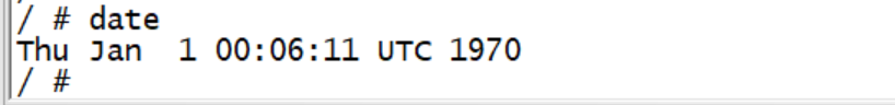
Fig. 3 current time value
As can be seen from Figure 3, the current time is 00:06:11, January 1, 1970. Obviously, the time is wrong and we need to reset it
Set RTC time.
2. Set RTC time
RTC time setting also uses the date command. Enter the "date--help" command to see how the date command sets the system time
The results are shown in Figure 4:
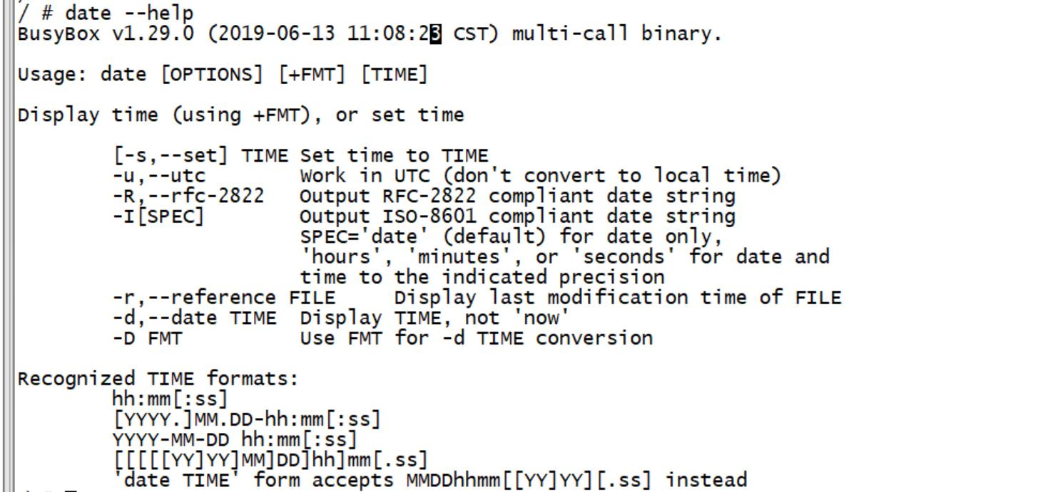
Figure 4. Help information for the date command
Now I want to set the current time to 18:13:00 on August 31, 2019, so enter the following command:
date -s "2019-08-31 18:13:00"
After setting, use the date command to check the current time again, and you will find that the time has changed, as shown in Figure 5:
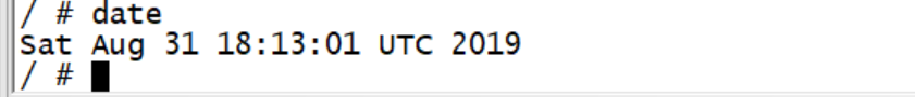
Figure 5 current time
Please note that we only set the current system time by using the "date-s" command, which has not been written into I.MX6U
In the RTC or other RTC chips, the time will be lost after the system is restarted. We need to change the current time
Write to RTC. Hwlock command is used here. Enter the following command to write the system time to RTC:
hwclock -w //Write the current system time into RTC
After the time is written into the RTC, there is no fear that the time will be lost after the system is restarted. If the backplane of the I.MX6U-ALPHA development board is connected
With the button battery, the development board will not lose time even if it is powered off. You can try to restart without power failure and restart after power failure
In both cases, the development board time will not be lost.