SPI drive
SPI is a very common serial communication interface, which is used to connect various peripherals, sensors and other devices Linux bare metal development | SPI experiment SPI interface has been introduced in detail in this paper. This paper mainly introduces the SPI driver framework under Linux, and writes SPI device drivers according to the framework
1, SPI drive frame
SPI driver framework is very similar to I2C. It is divided into host controller driver and device driver. Host controller is the SPI controller interface of SOC. Like I2C adapter driver, SPI host driver is generally written by SOC manufacturer
1.1 SPI host driver
SPI host driver is the SPI controller driver of SOC, and the kernel uses spi_master means SPI host driver, spi_master is a structure defined in include / Linux / SPI / SPI H file
struct spi_master {
	struct device dev;
	struct list_head list;
	......
	s16 bus_num;
	u16 num_chipselect;
	u16 dma_alignment;
	u16 mode_bits;
	u32 bits_per_word_mask;
	......
	u32 min_speed_hz;
	u32 max_speed_hz;
	u16 flags;
	......
	spinlock_t bus_lock_spinlock;
	struct mutex bus_lock_mutex;
	bool bus_lock_flag;
	......
	int (*setup)(struct spi_device *spi);
	......
	/* Controller data transfer function */
	int (*transfer)(struct spi_device *spi, struct spi_message *mesg);
	......
	/* It is used for SPI data transmission, and the transmitted data will be packaged into spi_message, which is sent in a queue */
	int (*transfer_one_message)(struct spi_master *master, struct spi_message *mesg);
	......
};
The core of SPI host driver is to apply for spi_master, and then initialize spi_master, and finally register SPI with the kernel_ master
- spi_master application and release
/************************* spi_master Apply for***************************/
struct spi_master *spi_alloc_master(struct device *dev, unsigned size)
//dev: device, usually platform_ dev member variable in device
//Size: private data size, which can be through SPI_ master_ get_ The devdata function gets the data
//Return value: applied spi_master
/************************* spi_master Release***************************/
void spi_master_put(struct spi_master *master)
//Master: SPI to release_ master
- spi_ Registration and cancellation of Master: SPI_ After the master is initialized, it needs to be registered with the kernel
/************************* spi_master Register***************************/
int spi_register_master(struct spi_master *master)
//Master: SPI to register_ master
//Return value: 0, successful; Negative value, failed
/************************* spi_master Write off***************************/
void spi_unregister_master(struct spi_master *master)
//Master: SPI to log off_ master
1.2 SPI device drive
The Linux kernel uses spi_driver structure to represent SPI device driver. When writing SPI device driver, we need to implement spi_driver. spi_ The driver structure is defined in include / Linux / SPI / SPI H file
struct spi_driver {
	const struct spi_device_id *id_table;
	int (*probe)(struct spi_device *spi);
	int (*remove)(struct spi_device *spi);
	void (*shutdown)(struct spi_device *spi);
	struct device_driver driver;
};
spi_ After the driver initialization is completed, it needs to register with the Linux kernel
- spi_driver registration function
int spi_register_driver(struct spi_driver *sdrv)
//sdrv: SPI to register_ driver
//Return value: 0, registration succeeded; Assignment, registration failed
- spi_driver logoff function
void spi_unregister_driver(struct spi_driver *sdrv)
//sdrv: SPI to log off_ driver
spi_ The driver registration example program is as follows:
/* probe function */
static int xxx_probe(struct spi_device *spi){
	/* Specific function content */
	return 0;
}
/* remove function */
static int xxx_remove(struct spi_device *spi){
	/* Specific function content */
	return 0;
}
/* Traditional matching method ID list */
static const struct spi_device_id xxx_id[] = {
	{"xxx", 0},
	{}
};
/* Device tree matching list */
static const struct of_device_id xxx_of_match[] = {
	{ .compatible = "xxx" },
	{ /* Sentinel */ }
};
/* SPI Drive structure */
static struct spi_driver xxx_driver = {
	.probe = xxx_probe,
	.remove = xxx_remove,
	.driver = {
		.owner = THIS_MODULE,
		.name = "xxx",
		.of_match_table = xxx_of_match,
	},
	.id_table = xxx_id,
};
/* Drive entry function */
static int __init xxx_init(void){
	return spi_register_driver(&xxx_driver);
}
/* Drive exit function */
static void __exit xxx_exit(void){
	spi_unregister_driver(&xxx_driver);
}

module_init(xxx_init);
module_exit(xxx_exit);
1.3 SPI equipment and drive matching process
The matching process between SPI device and driver is completed by SPI bus, which is spi_bus_type, defined in drivers / SPI / SPI C in the document
struct bus_type spi_bus_type = {
	.name = "spi",
	.dev_groups = spi_dev_groups,
	.match = spi_match_device,
	.uevent = spi_uevent,
};
It can be seen from the above that the matching function between SPI device and driver is spi_match_device, whose function contents are as follows:
static int spi_match_device(struct device *dev, struct device_driver *drv) {
	const struct spi_device *spi = to_spi_device(dev);
	const struct spi_driver *sdrv = to_spi_driver(drv);

	/* Used to complete device tree device and driver matching */
	if (of_driver_match_device(dev, drv))
		return 1;
	/* For ACPI form matching */
	if (acpi_driver_match_device(dev, drv))
		return 1;
	/* For traditional device tree free device and driver matching */
	if (sdrv->id_table)
		return !!spi_match_id(sdrv->id_table, spi);
	/* Compare whether the modalias member variable and the name member variable are equal */
	return strcmp(spi->modalias, drv->name) == 0;
}
1.4 SPI equipment data transceiver processing
When the SPI is successfully registered with the Linux kernel_ After the driver, you can use the API functions provided by the SPI core layer to read and write to the device. The first is spi_transfer structure, which is used to describe SPI transmission information. The structure is as follows:
struct spi_transfer {
	const void *tx_buf;	//Save the data to be sent
	void *rx_buf;		//Used to save received data
	unsigned len;		//Length of data to be transferred

	dma_addr_t tx_dma;
	dma_addr_t rx_dma;
	struct sg_table tx_sg;
	struct sg_table rx_sg;

	unsigned cs_change:1;
	unsigned tx_nbits:3;
	unsigned rx_nbits:3;
	#define SPI_NBITS_SINGLE 0x01 	/* 1bit transfer */
	#define SPI_NBITS_DUAL 0x02 	/* 2bits transfer */
	#define SPI_NBITS_QUAD 0x04 	/* 4bits transfer */
	u8 bits_per_word;
	u16 delay_usecs;
	u32 speed_hz;

	struct list_head transfer_list;
};
spi_transfer needs to be organized into spi_message, spi_message is also a structure, as follows:
struct spi_message {
	struct list_head transfers;
	struct spi_device *spi;
	unsigned is_dma_mapped:1;
	......
	/* completion is reported through a callback */
	void (*complete)(void *context);
	void *context;
	unsigned frame_length;
	unsigned actual_length;
	int status;

	struct list_head queue;
	void *state;
};
Using spi_message needs to be initialized before it
void spi_message_init(struct spi_message *m)
//m: SPI to initialize_ message
spi_ After message initialization, SPI needs to be initialized_ Add transfer to spi_message queue
void spi_message_add_tail(struct spi_transfer *t, struct spi_message *m)
//t: SPI to add to queue_ transfer
//m: spi_transfer the SPI to be added_ message
spi_ After message is ready, data transmission can be carried out. Data transmission is divided into synchronous transmission and asynchronous transmission
/***Synchronous transmission will be blocked and wait for SPI data transmission to complete***/
int spi_sync(struct spi_device *spi, struct spi_message *message)
//spi: spi for data transmission_ device
//Message: SPI to transfer_ message
/***Asynchronous transmission will not block waiting, so SPI needs to be set_ In message
complete Callback function, which will be called after the asynchronous transmission is completed***/
int spi_async(struct spi_device *spi, struct spi_message *message)
//spi: spi for data transmission_ device
//Message: SPI to transfer_ message
To sum up, the SPI data transmission example code is as follows:
/********** SPI Multibyte transmission**********/
static int spi_send(struct spi_device *spi, u8 *buf, int len){
	int ret;
	struct spi_message m;
	struct spi_transfer t = {	  //1. Define an spi_transfer structure variable and set member variable
		.tx_buf = buf,
		.len = len,
	};
	spi_message_init(&m); 		  //2. Initialize spi_message
	spi_message_add_tail(t, &m);  //3. SPI_ Add transfer to spi_message queue
	ret = spi_sync(spi, &m); 	  //4. Synchronous transmission
	return ret;
}
/********** SPI Multibyte reception**********/
static int spi_receive(struct spi_device *spi, u8 *buf, int len){
	int ret;
	struct spi_message m;
	struct spi_transfer t = {	  //1. Define an spi_transfer structure variable and set member variable
		.rx_buf = buf,
		.len = len,
	};
	spi_message_init(&m); 		  //2. Initialize spi_message
	spi_message_add_tail(t, &m);  //3. SPI_ Add transfer to spi_message queue
	ret = spi_sync(spi, &m);	  //4. Synchronous transmission
	return ret;
}
2, SPI drive experiment
This chapter introduces how to drive the six axis sensor of the SPI interface ICM-20608 on the I.MX6U-ALPHA development board, and read the original sensor data of ICM-20608 in the application program. For the introduction of ICM-20608 six axis sensor, please refer to Linux bare metal development | SPI experiment One article
2.1 modifying the equipment tree
- Modify or add the pinctrl node: add a child node in the iomuxc node to describe the SPI pin used by ICM20608. The child node name is pinctrl_ecspi3
pinctrl_ecspi3: icm20608 {
	fsl,pins = <
		MX6UL_PAD_UART2_TX_DATA__GPIO1_IO20 	0x10b0 	/* CS */
		MX6UL_PAD_UART2_RX_DATA__ECSPI3_SCLK 	0x10b1 	/* SCLK */
		MX6UL_PAD_UART2_RTS_B__ECSPI3_MISO 		0x10b1 	/* MISO */
		MX6UL_PAD_UART2_CTS_B__ECSPI3_MOSI 		0x10b1 	/* MOSI */
	>;
};
//UART2_TX_DATA is a chip selection signal. Because you want to control the chip selection signal yourself, it is multiplexed into ordinary GPIO
- Add child node: add icm20608 child node under ecspi3 node
&ecspi3 {
	fsl,spi-num-chipselects = <1>; 	//Set the current number of film selections to 1
	/* If the "CS gpios" attribute is used, the SPI host driver will control the chip selection pin */
	cs-gpio = <&gpio1 20 GPIO_ACTIVE_LOW>; 	/* cant't use cs-gpios! */
	pinctrl-names = "default";
	pinctrl-0 = <&pinctrl_ecspi3>;
	status = "okay";

	spidev: icm20608@0 {
		compatible = "alientek,icm20608";
		spi-max-frequency = <8000000>; 	//Set the SPI maximum clock frequency to 8MHz
		reg = <0>;
	};
};
- Check whether the pins conflict: check whether the pins set in pinctrl and specified in the device node are used by other peripherals
After saving the modifications, compile the device tree with the "make dtbs" command in the kernel home directory, and start the Linux system with the new device tree file
2.2 driver programming
- New icm20608reg H register header file
#ifndef ICM20608_H
#define ICM20608_H

#define ICM20608G_ID 			 0XAF 	/*  ID value*/
#define ICM20608D_ID 			 0XAE 	/*  ID value*/
/* Gyroscope and acceleration self-test (set during production, used to compare with the user's self-test output value) */
#define	ICM20_SELF_TEST_X_GYRO		0x00
#define	ICM20_SELF_TEST_Y_GYRO		0x01
#define	ICM20_SELF_TEST_Z_GYRO		0x02
#define	ICM20_SELF_TEST_X_ACCEL		0x0D
#define	ICM20_SELF_TEST_Y_ACCEL		0x0E
#define	ICM20_SELF_TEST_Z_ACCEL		0x0F
/* Gyro static offset */
#define	ICM20_XG_OFFS_USRH			0x13
#define	ICM20_XG_OFFS_USRL			0x14
#define	ICM20_YG_OFFS_USRH			0x15
#define	ICM20_YG_OFFS_USRL			0x16
#define	ICM20_ZG_OFFS_USRH			0x17
#define	ICM20_ZG_OFFS_USRL			0x18
#define	ICM20_SMPLRT_DIV			0x19
#define	ICM20_CONFIG				0x1A
#define	ICM20_GYRO_CONFIG			0x1B
#define	ICM20_ACCEL_CONFIG			0x1C
#define	ICM20_ACCEL_CONFIG2			0x1D
#define	ICM20_LP_MODE_CFG			0x1E
#define	ICM20_ACCEL_WOM_THR			0x1F
#define	ICM20_FIFO_EN				0x23
#define	ICM20_FSYNC_INT				0x36
#define	ICM20_INT_PIN_CFG			0x37
#define	ICM20_INT_ENABLE			0x38
#define	ICM20_INT_STATUS			0x3A
/* Acceleration output */
#define	ICM20_ACCEL_XOUT_H			0x3B
#define	ICM20_ACCEL_XOUT_L			0x3C
#define	ICM20_ACCEL_YOUT_H			0x3D
#define	ICM20_ACCEL_YOUT_L			0x3E
#define	ICM20_ACCEL_ZOUT_H			0x3F
#define	ICM20_ACCEL_ZOUT_L			0x40
/* Temperature output */
#define	ICM20_TEMP_OUT_H			0x41
#define	ICM20_TEMP_OUT_L			0x42
/* Gyroscope output */
#define	ICM20_GYRO_XOUT_H			0x43
#define	ICM20_GYRO_XOUT_L			0x44
#define	ICM20_GYRO_YOUT_H			0x45
#define	ICM20_GYRO_YOUT_L			0x46
#define	ICM20_GYRO_ZOUT_H			0x47
#define	ICM20_GYRO_ZOUT_L			0x48
#define	ICM20_SIGNAL_PATH_RESET		0x68
#define	ICM20_ACCEL_INTEL_CTRL 		0x69
#define	ICM20_USER_CTRL				0x6A
#define	ICM20_PWR_MGMT_1			0x6B
#define	ICM20_PWR_MGMT_2			0x6C
#define	ICM20_FIFO_COUNTH			0x72
#define	ICM20_FIFO_COUNTL			0x73
#define	ICM20_FIFO_R_W				0x74
#define	ICM20_WHO_AM_I 				0x75

/* Acceleration static offset */
#define	ICM20_XA_OFFSET_H			0x77
#define	ICM20_XA_OFFSET_L			0x78
#define	ICM20_YA_OFFSET_H			0x7A
#define	ICM20_YA_OFFSET_L			0x7B
#define	ICM20_ZA_OFFSET_H			0x7D
#define	ICM20_ZA_OFFSET_L 			0x7E

#endif
- New icm20608 C driver file
#define ICM20608_CNT	1
#define ICM20608_NAME	"icm20608"

struct icm20608_dev {
	dev_t devid;				/* Equipment number */
	struct cdev cdev;			/* cdev */
	struct class *class;		/* class */
	struct device *device;		/* equipment */
	struct device_node	*nd; 	/* Device node */
	int major;					/* Main equipment No */
	void *private_data;			/* Private data */
	int cs_gpio;				/* GPIO number used for chip selection */
	signed int gyro_x_adc;		/* Gyro X-axis original value */
	signed int gyro_y_adc;		/* Gyro Y-axis original value */
	signed int gyro_z_adc;		/* Gyro Z-axis original value */
	signed int accel_x_adc;		/* Original value of accelerometer X axis */
	signed int accel_y_adc;		/* Accelerometer Y-axis original value */
	signed int accel_z_adc;		/* Original value of accelerometer Z axis */
	signed int temp_adc;		/* Original temperature value */
};
static struct icm20608_dev icm20608dev;
/* Reading multiple register data from icm20608 */
static int icm20608_read_regs(struct icm20608_dev *dev, u8 reg, void *buf, int len){
	int ret;
	unsigned char txdata[len];
	struct spi_message m;
	struct spi_transfer *t;
	struct spi_device *spi = (struct spi_device *)dev->private_data;

	gpio_set_value(dev->cs_gpio, 0);				/* Lower the film selection and select ICM20608 */
	t = kzalloc(sizeof(struct spi_transfer), GFP_KERNEL);	/* Request memory */
	/* For the first time, send the deposit address to be read */
	txdata[0] = reg | 0x80;		/* When writing data, the register address bit8 should be set to 1 */
	t->tx_buf = txdata;			/* Data to send */
	t->len = 1;					/* 1 Bytes */
	spi_message_init(&m);		/* Initialize spi_message */
	spi_message_add_tail(t, &m);/* SPI_ Add transfer to spi_message queue */
	ret = spi_sync(spi, &m);	/* Synchronous transmission */
	/* The second time, read the data */
	txdata[0] = 0xff;			/* Any value is meaningless here */
	t->rx_buf = buf;			/* Read data */
	t->len = len;				/* Length of data to read */
	spi_message_init(&m);		/* Initialize spi_message */
	spi_message_add_tail(t, &m);/* SPI_ Add transfer to spi_message queue */
	ret = spi_sync(spi, &m);	/* Synchronous transmission */

	kfree(t);									/* Free memory */
	gpio_set_value(dev->cs_gpio, 1);			/* The chip selection is pulled up and ICM20608 is released */

	return ret;
}
/* Write data to icm20608 multiple registers */
static s32 icm20608_write_regs(struct icm20608_dev *dev, u8 reg, u8 *buf, u8 len){
	int ret;
	unsigned char txdata[len];
	struct spi_message m;
	struct spi_transfer *t;
	struct spi_device *spi = (struct spi_device *)dev->private_data;

	t = kzalloc(sizeof(struct spi_transfer), GFP_KERNEL);	/* Request memory */
	gpio_set_value(dev->cs_gpio, 0);			/* Film selection pull down */
	/* For the first time, send the deposit address to be read */
	txdata[0] = reg & ~0x80;	/* When writing data, the register address bit8 should be cleared */
	t->tx_buf = txdata;			/* Data to send */
	t->len = 1;					/* 1 Bytes */
	spi_message_init(&m);		/* Initialize spi_message */
	spi_message_add_tail(t, &m);/* SPI_ Add transfer to spi_message queue */
	ret = spi_sync(spi, &m);	/* Synchronous transmission */
	/* The second time, send the data to be written */
	t->tx_buf = buf;			/* Data to write */
	t->len = len;				/* Bytes written */
	spi_message_init(&m);		/* Initialize spi_message */
	spi_message_add_tail(t, &m);/* SPI_ Add transfer to spi_message queue */
	ret = spi_sync(spi, &m);	/* Synchronous transmission */

	kfree(t);					/* Free memory */
	gpio_set_value(dev->cs_gpio, 1);/* The chip selection is pulled up and ICM20608 is released */
	return ret;
}
/* Read the specified register value of icm20608 and read a register */
static unsigned char icm20608_read_onereg(struct icm20608_dev *dev, u8 reg){
	u8 data = 0;
	icm20608_read_regs(dev, reg, &data, 1);
	return data;
}
/* Writes the specified value to the icm20608 specified register */
static void icm20608_write_onereg(struct icm20608_dev *dev, u8 reg, u8 value){
	u8 buf = value;
	icm20608_write_regs(dev, reg, &buf, 1);
}
/* Read the data of ICM20608 and read the original data */
void icm20608_readdata(struct icm20608_dev *dev){
	unsigned char data[14];
	icm20608_read_regs(dev, ICM20_ACCEL_XOUT_H, data, 14);

	dev->accel_x_adc = (signed short)((data[0] << 8) | data[1]);
	dev->accel_y_adc = (signed short)((data[2] << 8) | data[3]);
	dev->accel_z_adc = (signed short)((data[4] << 8) | data[5]);
	dev->temp_adc    = (signed short)((data[6] << 8) | data[7]);
	dev->gyro_x_adc  = (signed short)((data[8] << 8) | data[9]);
	dev->gyro_y_adc  = (signed short)((data[10] << 8) | data[11]);
	dev->gyro_z_adc  = (signed short)((data[12] << 8) | data[13]);
}
/* open device */
static int icm20608_open(struct inode *inode, struct file *filp){
	filp->private_data = &icm20608dev; /* Set private data */
	return 0;
}
/* Read data from device */
static ssize_t icm20608_read(struct file *filp, char __user *buf, size_t cnt, loff_t *off){
	signed int data[7];
	long err = 0;
	struct icm20608_dev *dev = (struct icm20608_dev *)filp->private_data;

	icm20608_readdata(dev);
	data[0] = dev->gyro_x_adc;
	data[1] = dev->gyro_y_adc;
	data[2] = dev->gyro_z_adc;
	data[3] = dev->accel_x_adc;
	data[4] = dev->accel_y_adc;
	data[5] = dev->accel_z_adc;
	data[6] = dev->temp_adc;
	err = copy_to_user(buf, data, sizeof(data));
	return 0;
}
/* Turn off / release the device */
static int icm20608_release(struct inode *inode, struct file *filp){
	return 0;
}
/* icm20608 Operation function */
static const struct file_operations icm20608_ops = {
	.owner = THIS_MODULE,
	.open = icm20608_open,
	.read = icm20608_read,
	.release = icm20608_release,
};
/* ICM20608 Internal register initialization function */
void icm20608_reginit(void){
	u8 value = 0;

	icm20608_write_onereg(&icm20608dev, ICM20_PWR_MGMT_1, 0x80);
	mdelay(50);
	icm20608_write_onereg(&icm20608dev, ICM20_PWR_MGMT_1, 0x01);
	mdelay(50);

	value = icm20608_read_onereg(&icm20608dev, ICM20_WHO_AM_I);
	printk("ICM20608 ID = %#X\r\n", value);

	icm20608_write_onereg(&icm20608dev, ICM20_SMPLRT_DIV, 0x00); 	/* The output rate is the internal sampling rate					*/
	icm20608_write_onereg(&icm20608dev, ICM20_GYRO_CONFIG, 0x18); 	/* Gyroscope ± 2000dps range 				*/
	icm20608_write_onereg(&icm20608dev, ICM20_ACCEL_CONFIG, 0x18); 	/* Accelerometer ± 16G range 					*/
	icm20608_write_onereg(&icm20608dev, ICM20_CONFIG, 0x04); 		/* Gyro low pass filter BW=20Hz 				*/
	icm20608_write_onereg(&icm20608dev, ICM20_ACCEL_CONFIG2, 0x04); /* Accelerometer low pass filter BW=21.2Hz 			*/
	icm20608_write_onereg(&icm20608dev, ICM20_PWR_MGMT_2, 0x00); 	/* Turn on all axes of accelerometer and gyroscope 				*/
	icm20608_write_onereg(&icm20608dev, ICM20_LP_MODE_CFG, 0x00); 	/* Turn off low power consumption 						*/
	icm20608_write_onereg(&icm20608dev, ICM20_FIFO_EN, 0x00);		/* Close FIFO						*/
}
/* spi The probe function of the driver. This function will be executed after the driver matches the device */
static int icm20608_probe(struct spi_device *spi){
	int ret = 0;

	/* 1,Build equipment number */
	if (icm20608dev.major) {
		icm20608dev.devid = MKDEV(icm20608dev.major, 0);
		register_chrdev_region(icm20608dev.devid, ICM20608_CNT, ICM20608_NAME);
	} else {
		alloc_chrdev_region(&icm20608dev.devid, 0, ICM20608_CNT, ICM20608_NAME);
		icm20608dev.major = MAJOR(icm20608dev.devid);
	}
	/* 2,Register device */
	cdev_init(&icm20608dev.cdev, &icm20608_ops);
	cdev_add(&icm20608dev.cdev, icm20608dev.devid, ICM20608_CNT);
	/* 3,Create class */
	icm20608dev.class = class_create(THIS_MODULE, ICM20608_NAME);
	if (IS_ERR(icm20608dev.class)) {
		return PTR_ERR(icm20608dev.class);
	}
	/* 4,Create device */
	icm20608dev.device = device_create(icm20608dev.class, NULL, icm20608dev.devid, NULL, ICM20608_NAME);
	if (IS_ERR(icm20608dev.device)) {
		return PTR_ERR(icm20608dev.device);
	}

	/* Obtain the cs chip selection signal in the device tree */
	icm20608dev.nd = of_find_node_by_path("/soc/aips-bus@02000000/spba-bus@02000000/ecspi@02010000");
	if(icm20608dev.nd == NULL) {
		printk("ecspi3 node not find!\r\n");
		return -EINVAL;
	}

	/* 2, Get the gpio attribute in the device tree and get the BEEP number used by BEEP */
	icm20608dev.cs_gpio = of_get_named_gpio(icm20608dev.nd, "cs-gpio", 0);
	if(icm20608dev.cs_gpio < 0) {
		printk("can't get cs-gpio");
		return -EINVAL;
	}

	/* 3,Set GPIO1_IO20 is an output and outputs a high level */
	ret = gpio_direction_output(icm20608dev.cs_gpio, 1);
	if(ret < 0) {
		printk("can't set gpio!\r\n");
	}

	/*Initialize spi_device */
	spi->mode = SPI_MODE_0;	/*MODE0,CPOL=0,CPHA=0*/
	spi_setup(spi);
	icm20608dev.private_data = spi; /* Set private data */

	/* Initialize ICM20608 internal register */
	icm20608_reginit();
	return 0;
}
/* spi The remove function of the spi driver. This function will be executed when the spi driver is removed */
static int icm20608_remove(struct spi_device *spi){
	/* Delete device */
	cdev_del(&icm20608dev.cdev);
	unregister_chrdev_region(icm20608dev.devid, ICM20608_CNT);

	/* Unregister classes and devices */
	device_destroy(icm20608dev.class, icm20608dev.devid);
	class_destroy(icm20608dev.class);
	return 0;
}
/* Traditional matching method ID list */
static const struct spi_device_id icm20608_id[] = {
	{"alientek,icm20608", 0},
	{}
};
/* Device tree matching list */
static const struct of_device_id icm20608_of_match[] = {
	{ .compatible = "alientek,icm20608" },
	{ /* Sentinel */ }
};
/* SPI Drive structure */
static struct spi_driver icm20608_driver = {
	.probe = icm20608_probe,
	.remove = icm20608_remove,
	.driver = {
			.owner = THIS_MODULE,
		   	.name = "icm20608",
		   	.of_match_table = icm20608_of_match,
		   },
	.id_table = icm20608_id,
};
/* Drive entry function */
static int __init icm20608_init(void){
	return spi_register_driver(&icm20608_driver);
}
/* Drive exit function */
static void __exit icm20608_exit(void){
	spi_unregister_driver(&icm20608_driver);
}

module_init(icm20608_init);
module_exit(icm20608_exit);
MODULE_LICENSE("GPL");
2.3 test program preparation
Create a new icm20608app C) test documents
int main(int argc, char *argv[])
{
int fd;
char *filename;
signed int databuf[7];
unsigned char data[14];
signed int gyro_x_adc, gyro_y_adc, gyro_z_adc;
signed int accel_x_adc, accel_y_adc, accel_z_adc;
signed int temp_adc;
float gyro_x_act, gyro_y_act, gyro_z_act;
float accel_x_act, accel_y_act, accel_z_act;
float temp_act;
int ret = 0;
if (argc != 2) {
printf("Error Usage!\r\n");
return -1;
}
filename = argv[1];
fd = open(filename, O_RDWR);
if(fd < 0) {
printf("can't open file %s\r\n", filename);
return -1;
}
while (1) {
ret = read(fd, databuf, sizeof(databuf));
if(ret == 0) { /* Data read successfully */
gyro_x_adc = databuf[0];
gyro_y_adc = databuf[1];
gyro_z_adc = databuf[2];
accel_x_adc = databuf[3];
accel_y_adc = databuf[4];
accel_z_adc = databuf[5];
temp_adc = databuf[6];
/* Calculate actual value */
gyro_x_act = (float)(gyro_x_adc) / 16.4;
gyro_y_act = (float)(gyro_y_adc) / 16.4;
gyro_z_act = (float)(gyro_z_adc) / 16.4;
accel_x_act = (float)(accel_x_adc) / 2048;
accel_y_act = (float)(accel_y_adc) / 2048;
accel_z_act = (float)(accel_z_adc) / 2048;
temp_act = ((float)(temp_adc) - 25 ) / 326.8 + 25;
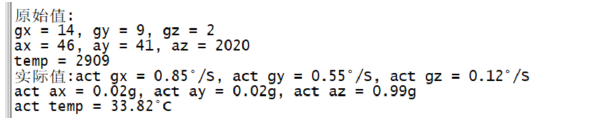
printf("\r\n Original value:\r\n");
printf("gx = %d, gy = %d, gz = %d\r\n", gyro_x_adc, gyro_y_adc, gyro_z_adc);
printf("ax = %d, ay = %d, az = %d\r\n", accel_x_adc, accel_y_adc, accel_z_adc);
printf("temp = %d\r\n", temp_adc);
printf("actual value:");
printf("act gx = %.2f°/S, act gy = %.2f°/S, act gz = %.2f°/S\r\n", gyro_x_act, gyro_y_act, gyro_z_act);
printf("act ax = %.2fg, act ay = %.2fg, act az = %.2fg\r\n", accel_x_act, accel_y_act, accel_z_act);
printf("act temp = %.2f°C\r\n", temp_act);
}
usleep(100000); /*100ms */
}
close(fd); /* Close file */
return 0;
}
2.4 operation test
- Modify Makefile compilation target variable
obj-m := icm20608.o
- Use "make -j32" to compile the driver module file
make -j32
icm20608App. Floating point calculation is used in C, and I.MX6U supports hardware floating point. Therefore, the following parameters can be added during compilation to enable hardware floating point
-march=armv7-a -mfpu=neon -mfloat=hard
- Compile the test APP with the command "arm linux gnueabihf GCC - march-armv7-a - mfpu neon - mfload = hard"
arm-linux-gnueabihf-gcc -march=armv7-a -mfpu=neon -mfloat=hard icm20608App.c -o icm20608App
-
Copy the driver file and APP executable file to "rootfs/lib/modules/4.1.15"
-
Use the "modprobe" command to load the driver. After loading successfully, the bus will be matched
depmod  #When loading the driver for the first time, use the "depmod" command
modprobe icm20608.ko
- After loading successfully, use the following command to test. APP continuously reads data from icm20608 and outputs it to the terminal
./icm20608App /dev/icm20608