catalogue
2, File list of pin control subsystem
2.2} and other kernel module interface header files
2.3 Low level pin controller driver interface
III. software framework diagram of pin control subsystem
3.1 function and Interface Overview
3.2 interface relationship between pin control subsystem and other linux kernel modules
3.3 pin control subsystem internal block diagram
4, Interface provided by pin control subsystem to other driver s
5, Interact with GPIO subsystem
5.1 why does the pin control subsystem interact with the GPIO subsystem?
5.2.3 pinctrl_gpio_direction_input/pinctrl_gpio_direction_output
6, Interface with driving model
7, Interface related to device tree or machine driver
7.2 establish pin mapping database through the data statically defined by machine driver
7.3 create pin mapping database through device tree
8, Interface specifications of core driver and low level pin controller driver
1, Foreword
In Linux 2 Embedded software engineers working on the 6 kernel will encounter this situation on the pin control:
(1) After starting a new project, you need to encode the pin control according to the settings of the hardware platform. For example, create a large table in the bootloader to describe the configuration and default state of each pin. In addition, since the pins of SOC can be reused, the pins may also be configured in each specific driver. These tasks are cumbersome and require great patience and detail.
(2) It is found that a driver cannot work normally. After hard debug ging, it is found that it is only because other drivers modify the pin configuration during initialization, resulting in their own drivers not working normally
(3) Even if the main CPU is the same project, due to different peripherals, we cannot use a kernel image, but we must modify the code (these codes are mainly board specific startup code)
(4) The code is not very neat, cut and pasted code is flying everywhere, and there are too many redundant codes in linux
As an embedded software engineer, if you do more projects, you will contact more CPU s and fall more. Then you will naturally think about whether we can solve the above problems? In addition, for those SOCS based on ARM core, although each SOC looks different on the surface, there are many same contents on pin control. Can it be extracted for further abstraction? The kernel in the new version (taking the kernel of version 4.14 as an example) proposes a pin control subsystem to solve these problems.
2, File list of pin control subsystem
2.1 source file list
We sort out the source file list of pin control subsystem in linux/drivers/pinctrl directory as follows:
| file name | describe |
|---|---|
| core.c core.h | core driver of pin control subsystem |
| pinctrl-utils.c | pinctrl-utils.h. some utility interface functions of pin control subsystem |
| pinmux.c pinmux.h | Core driver of pin control subsystem (code of pin boxing part, also known as pinmux driver) |
| pinconf.c pinconf.h | Core driver of pin control subsystem (code of pin config part, also known as pin config driver) |
| device7tree.c devicetree.h | device tree code of pin control subsystem |
| pinctrl-xxxx.c | Low level drivers for various pin controller s |
2.2} and other kernel module interface header files
Many other modules of the kernel need to use the services of the pin control subsystem. These header files define the external interfaces and related data structures of the pin control subsystem. We sorted out the list of external interface header files of pin control subsystem under linux/include/linux/pinctrl directory as follows:
| file name | describe |
| consumer.h | Other driver s should use the following interfaces of the pin control subsystem: a. set pin multiplexing function b. configure the electrical characteristics of the pins You need the include header file at this time |
| devinfo.h | This is the interface used by the driver model of the for linux kernel. A struct dev is included in struct device_ pin_ Info * pins. This member describes the initial state information of the pin of the device. Before the probe, the core driver in the driver model will set the pin state before calling the probe function of the driver |
| machine.h | Interface with machine module. |
2.3 Low level pin controller driver interface
We sorted out the header files provided by the pin control subsystem to the underlying specific pin controller driver in the linux/include/linux/pinctrl directory as follows:
| File name | Description |
| pinconf-generic.h | This interface is mainly used by various pin controller driver s, not external interfaces. |
| pinconf.h | pin configuration interface |
| pinctrl-state.h | pin control state definition |
| pinmux.h | pin mux function interface |
III. software framework diagram of pin control subsystem
3.1 function and Interface Overview
Generally speaking, learning complex software components or software modules is a painful process. We can regard the software block we want to learn as a black box. No matter how complex it is, the first step is always to understand its functions and external interface characteristics. If you like, you can not look at its internal implementation, first think about its internal logic and form a number of problems, and then look at the code with these problems.
(1) Functional specifications. The main functions of the pin control subsystem include:
(A) Manage all controllable pins in the system. During system initialization, enumerate all controllable pins and identify them.
(B) Manage the Multiplexing of these pins. For SOC, in addition to configuring its pins as ordinary GPIO, several pins can also form a pin group to form specific functions. For example, pin number is {0, 8, 16, 24}. These four pins are combined to form a pin group, which provides the function of SPI. The pin control subsystem manages all pin groups.
(C) Configure the characteristics of these pins. For example, configure the pull-up/down resistance on this pin, configure drive strength, etc
(2) Interface specifications. A software component of the linux kernel must be placed back in the linux system before its interface and position in the system can be easily discussed. Therefore, in the second section of this chapter, the interfaces of each pin control subsystem and other kernel modules will be described based on the system block.
(3) Internal logic. To study the internal logic of a subsystem, first open the black box and subdivide the modules, and then conduct function analysis, external interface analysis and internal logic analysis for each module. If the module is still large and difficult to master, continue to subdivide it into sub modules and repeat the above analysis process. In Section 3 of this chapter, we open the black box of the pin control subsystem for further analysis.
3.2 interface relationship between pin control subsystem and other linux kernel modules
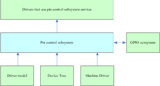
The pin control subsystem will provide interfaces to other drivers in the system to set the pin config and pin mux of the driver. The interfaces of this part are described in Chapter 4. Ideally, GPIO control driver only interacts with pin control subsystem like UART and SPI. However, due to various sources (described later), pin control subsystem and GPIO subsystem must interact. The interfaces of this part are described in Chapter 5. Chapter 6 describes the interface between Driver model and pin control subsystem, and Chapter 7 describes the interface between Device Tree and Machine driver that provide database support for pin control subsystem.
3.3 pin control subsystem internal block diagram
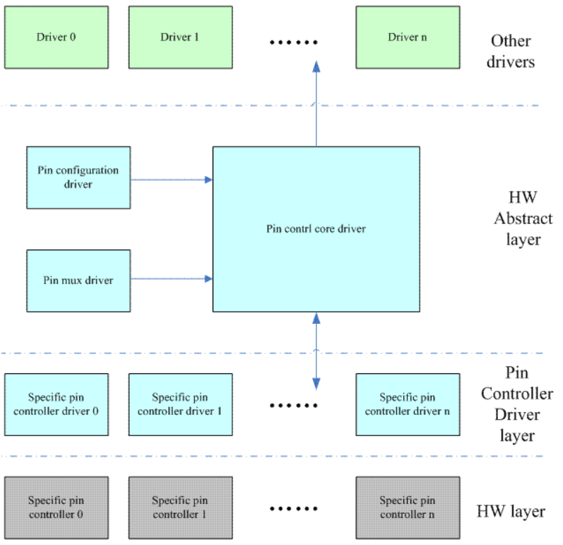
After understanding the interface at first, it is easy to read and analyze the internal logic of the pin control subsystem. This paper will not analyze it.
4, Interface provided by pin control subsystem to other driver s
When you are going to write an ordinary linux driver (such as serial driver), what do you expect the interface provided by the pin control subsystem to look like? Simple. Of course, it's best to be simple. It's best to have no interface. Of course, this is possible. For details, please refer to the interface in Chapter 6.
4.1 General
The main objectives of calling pin control subsystem by ordinary driver are:
(1) Set the function reuse of the device. To set the function reuse of a device, you need to understand two concepts: function and pin group. Function is a function abstraction, corresponding to a HW logic block, such as SPI0. Although given a specific gunction name, we are not sure about the pins it uses. For example, in order to design flexibly, the functions of SPI0 inside the chip may be led to pin group {A8, a7, A6, A5} or another pin group {G4, G3, G2, G1}. However, there is no doubt that the two pin groups cannot be active at the same time. After all, there is only one logic function circuit of SPI0 inside the chip. Therefore, function mux can be set only when function selector (the so-called selector is an ID or index) and function pin group selector are given.
(2) Set the electrical characteristics of those pin s corresponding to the device.
In addition, due to the requirements of power management, a device may be in a power management state, such as idle or sleep. At this time, all pins belonging to the device need to be in another state. Based on the above requirements, we define the concept of pin control state, that is, the device driver can switch the state of the device in one of many states. In order to facilitate the management of pin control state, we propose a concept of pin control state holder to manage all pin control states of a device. Therefore, the interface of ordinary driver calling pin control subsystem logically mainly includes:
(1) Gets the handle to the pin control state holder
(2) Set pin control status
(3) Release handle of pin control state holder
The definition of pin control state holder is as follows:
/**
 * struct pinctrl - per-device pin control state holder
 * @node: global list node
 * @dev: the device using this pin control handle
 * @states: a list of states for this device
 * @state: the current state
 * @dt_maps: the mapping table chunks dynamically parsed from device tree for
 *	this device, if any
 * @users: reference count
 */
struct pinctrl {
    struct list_head node;			// pin control state holder of all device s in the system
                                       It is hung into a global linked list
    struct device *dev;				// device corresponding to the pin control state holder
    struct list_head states;		// All States of the device are linked to the linked list
    struct pinctrl_state *state;	// Current pin control state
    struct list_head dt_maps;		// mapping table
    struct kref users;				// reference count
};
Every device in the system that needs to interact with the pin control subsystem needs to obtain this handle before setting. All states belonging to the device are linked to a linked list. The chain header is the states member of the pin control state holder. A state is defined as follows:
/**
 * struct pinctrl_state - a pinctrl state for a device
 * @node: list node for struct pinctrl's @states field
 * @name: the name of this state
 * @settings: a list of settings for this state
 */
struct pinctrl_state {
    struct list_head node;		// Node linked to the chain header
    const char *name;			// The name of the state
    struct list_head settings;	// All settings belonging to this state
};
A pin state contains several settings. All settings are linked to a linked list. The chain header is the settings member in the pin state, which is defined as follows:
/**
 * struct pinctrl_setting - an individual mux or config setting
 * @node: list node for struct pinctrl_settings's @settings field
 * @type: the type of setting
 * @pctldev: pin control device handling to be programmed. Not used for
 *   PIN_MAP_TYPE_DUMMY_STATE.
 * @dev_name: the name of the device using this state
 * @data: Data specific to the setting type
 */
struct pinctrl_setting {
	struct list_head node;
	enum pinctrl_map_type type;
	struct pinctrl_dev *pctldev;
	const char *dev_name;
	union {
		struct pinctrl_setting_mux mux;
		struct pinctrl_setting_configs configs;
	} data;
};
When the driver sets a pin state, the pin control subsystem will traverse the settings linked list of the state and set settings one by one. These settings have various types and are defined as follows:
enum pinctrl_map_type {
    PIN_MAP_TYPE_INVALID,
    PIN_MAP_TYPE_DUMMY_STATE,
    PIN_MAP_TYPE_MUX_GROUP,				// setting of function reuse
    PIN_MAP_TYPE_CONFIGS_PIN,			// Set the electrical characteristics of a single pin
    PIN_MAP_TYPE_CONFIGS_GROUP,			// Set the electrical characteristics of a single pin group
};
There are settings related to pin mux (PIN_MAP_TYPE_MUX_GROUP), which are defined as follows:
/**
 * struct pinctrl_setting_mux - setting data for MAP_TYPE_MUX_GROUP
 * @group: the group selector to program
 * @func: the function selector to program
 */
struct pinctrl_setting_mux {
    unsigned group;						// The group selector corresponding to this setting
    unsigned func;						// function selector corresponding to this setting
};
With the function selector and the g roup selector belonging to the function group, you can set the device and pin mux related settings. The settings for setting electrical characteristics are defined as follows:
/**
 * struct pinctrl_map_configs - mapping table content for MAP_TYPE_CONFIGS_*
 * @group_or_pin: the name of the pin or group whose configuration parameters
 *	are to be configured.
 * @configs: a pointer to an array of config parameters/values to program into
 *	hardware. Each individual pin controller defines the format and meaning
 *	of config parameters.
 * @num_configs: the number of entries in array @configs
 */
struct pinctrl_map_configs {
    const char *group_or_pin		// The name of the pin or pin group
    unsigned long *configs;			// List of values to set. This value is used to write HW
    unsigned num_configs;			// Number of values in the list
};
4.2 specific interfaces
(1) devm_pinctrl_get and pinctrl_get. devm_pinctrl_get is the Resource managed version of pinctrl_get, core or pinctrl_get function. These two interfaces are the pin control state holder (struct pinctrl) of the device (struct device in the device model). Pin control state holder is not statically defined. It is usually created dynamically when the function is called for the first time. Creating a pin control state holder is a big project. Let's analyze this code.
static struct pinctrl *create_pinctrl(struct device *dev,
				      struct pinctrl_dev *pctldev)
{
	struct pinctrl *p;
	const char *devname;
	struct pinctrl_maps *maps_node;
	int i;
	const struct pinctrl_map *map;
	int ret;

	/*
	 * create the state cookie holder struct pinctrl for each
	 * mapping, this is what consumers will get when requesting
	 * a pin control handle with pinctrl_get()
	 */
	p = kzalloc(sizeof(*p), GFP_KERNEL);   // Assign pin control state hold
r Occupied memory and initialized
	if (!p)
		return ERR_PTR(-ENOMEM);
	p->dev = dev;
	INIT_LIST_HEAD(&p->states);
	INIT_LIST_HEAD(&p->dt_maps);

	/*mapping table The establishment of this database is also dynamic. When pin control state is called for the first time
holder When the get function of is called, it will call pinctrl_dt_to_map to create the mapping required by the device
entry. Please refer to Chapter VII for details.*/
	ret = pinctrl_dt_to_map(p, pctldev);
	if (ret < 0) {
		kfree(p);
		return ERR_PTR(ret);
	}

	devname = dev_name(dev);

	mutex_lock(&pinctrl_maps_mutex);
	/* Iterate over the pin control maps to locate the right ones */
	for_each_maps(maps_node, i, map) {
		/* Map must be for this device */
		if (strcmp(map->dev_name, devname))
			continue;
		/*
		 * If pctldev is not null, we are claiming hog for it,
		 * that means, setting that is served by pctldev by itself.
		 *
		 * Thus we must skip map that is for this device but is served
		 * by other device.
		 */
		if (pctldev &&
		    strcmp(dev_name(pctldev->dev), map->ctrl_dev_name))
			continue;

		ret = add_setting(p, pctldev, map);  //Analyze a mapping entry,
Take this setting Add your code to holder in
		/*
		 * At this point the adding of a setting may:
		 *
		 * - Defer, if the pinctrl device is not yet available
		 * - Fail, if the pinctrl device is not yet available,
		 *   AND the setting is a hog. We cannot defer that, since
		 *   the hog will kick in immediately after the device
		 *   is registered.
		 *
		 * If the error returned was not -EPROBE_DEFER then we
		 * accumulate the errors to see if we end up with
		 * an -EPROBE_DEFER later, as that is the worst case.
		 */
		if (ret == -EPROBE_DEFER) {
			pinctrl_free(p, false);
			mutex_unlock(&pinctrl_maps_mutex);
			return ERR_PTR(ret);
		}
	}
	mutex_unlock(&pinctrl_maps_mutex);

	if (ret < 0) {
		/* If some other error than deferral occurred, return here */
		pinctrl_free(p, false);
		return ERR_PTR(ret);
	}

	kref_init(&p->users);

	/* Add the pinctrl handle to the global list */
	/* Add the newly added pin control state holder to the global linked list */
	mutex_lock(&pinctrl_list_mutex);
	list_add_tail(&p->node, &pinctrl_list);
	mutex_unlock(&pinctrl_list_mutex);

	return p;
}
(2)devm_pinctrl_put and pinctrl_put. Is the inverse function in the (1) interface. devm_pinctrl_get and pinctrl_ When get gets the handle, it applies for a lot of resources in devm_pinctrl_put and pinctrl_put can be released. It should be noted that multiple calls to the get function will not repeatedly allocate resources, but only increase the reference count by one and decrease the reference count by one in the put. Only when count = = 0 will all resources held by the device's pin control state holder be released.
(3)pinctrl_lookup_state. Find the corresponding pin control state in the pin control state holder according to the state name. The specific state is defined by each device, but the pin control subsystem defines some standard pin control states, which are defined in pinctrl state H file
/**
 * @PINCTRL_STATE_DEFAULT: the state the pinctrl handle shall be put
 *	into as default, usually this means the pins are up and ready to
 *	be used by the device driver. This state is commonly used by
 *	hogs to configure muxing and pins at boot, and also as a state
 *	to go into when returning from sleep and idle in
 *	.pm_runtime_resume() or ordinary .resume() for example.
 * @PINCTRL_STATE_INIT: normally the pinctrl will be set to "default"
 *	before the driver's probe() function is called.  There are some
 *	drivers where that is not appropriate becausing doing so would
 *	glitch the pins.  In those cases you can add an "init" pinctrl
 *	which is the state of the pins before drive probe.  After probe
 *	if the pins are still in "init" state they'll be moved to
 *	"default".
 * @PINCTRL_STATE_IDLE: the state the pinctrl handle shall be put into
 *	when the pins are idle. This is a state where the system is relaxed
 *	but not fully sleeping - some power may be on but clocks gated for
 *	example. Could typically be set from a pm_runtime_suspend() or
 *	pm_runtime_idle() operation.
 * @PINCTRL_STATE_SLEEP: the state the pinctrl handle shall be put into
 *	when the pins are sleeping. This is a state where the system is in
 *	its lowest sleep state. Could typically be set from an
 *	ordinary .suspend() function.
 */
#define PINCTRL_STATE_DEFAULT "default"
#define PINCTRL_STATE_INIT "init"
#define PINCTRL_STATE_IDLE "idle"
#define PINCTRL_STATE_SLEEP "sleep"
(4)pinctrl_select_state. Set a specific pin control state interface.
5, Interact with GPIO subsystem
5.1 why does the pin control subsystem interact with the GPIO subsystem?
As a software engineer, we expect the hardware design to be as follows:
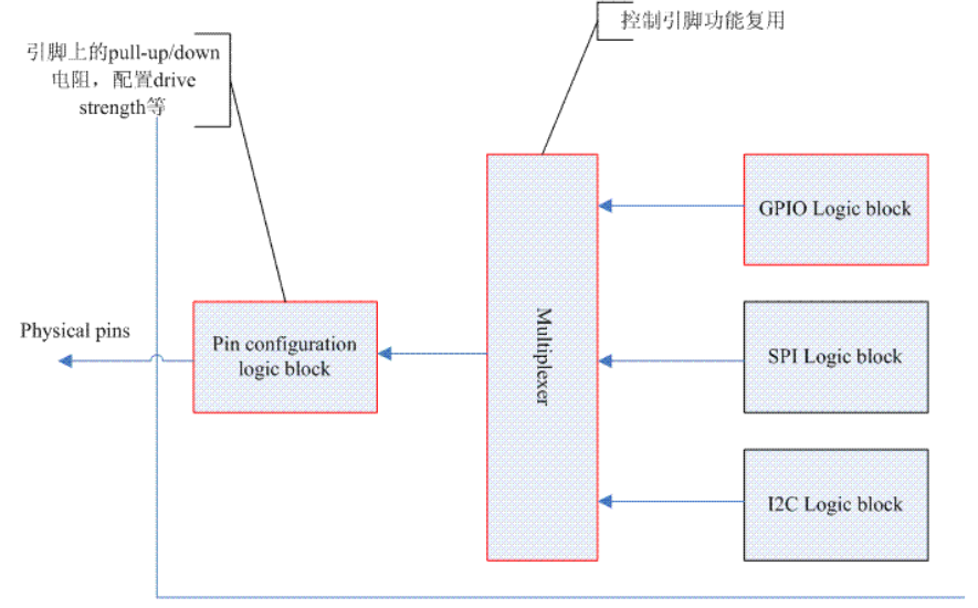
The HW block of GPIO should be equivalent to the blocks multiplexed by other functions. They are jointly input to a multiplexer block. The register of this block controls which functional circuit is currently active. pin configuration is global. No matter which function is active, you can set the electrical characteristics for the pin. Under this architecture, the three blocks with red borders in the figure above are completely independent HW blocks, and their control registers should be described in three chapters in the SOC datasheet. At the same time, the registers of these blocks should be in different address ranges.
For software engineers, we can make the pin control subsystem and GPIO subsystem completely independent, initialize them respectively, and map their own register address space. For the pin control subsystem, GPIO is no different from other HW block s, but uses a software module that provides its own services. However, in fact, SoC design is not always as expected by software engineers. The design framework of some SOC is as follows:
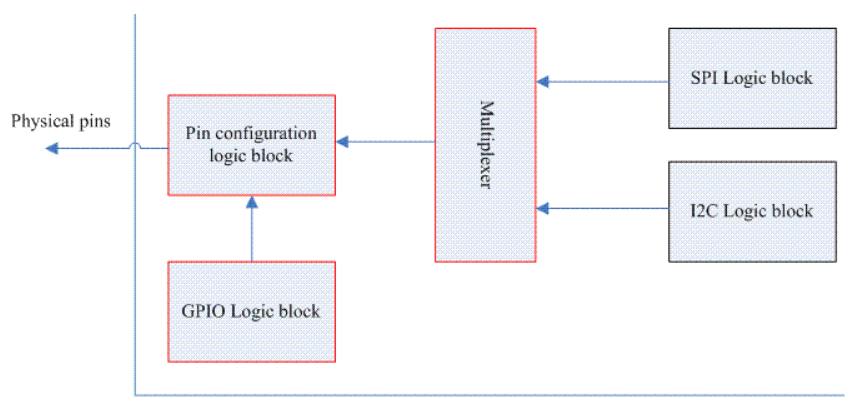
At this time, GPIO block s are always active, while the three blocks with red borders are tightly bound, and their registers occupy a memory range (these three blocks are described in a chapter in the datasheet). At this time, the software engineer is a little tangled. The GPIO control that does not belong to me is also forced to participate. At this time, the control of hardware registers is handled by the pin controller. All GPIO related operations must pass through the pin controller driver. At this time, the pin controller driver appears as the back end of the GPIO driver.
5.2 specific interface form
5.2.1 pinctrl_request_gpio
This interface is mainly used to apply for GPIO. GPIO is also a resource, which should be request ed before use and released after use. The specific codes are as follows:
/**
 * pinctrl_request_gpio() - request a single pin to be used as GPIO
 * @gpio: the GPIO pin number from the GPIO subsystem number space
 *
 * This function should *ONLY* be used from gpiolib-based GPIO drivers,
 * as part of their gpio_request() semantics, platforms and individual drivers
 * shall *NOT* request GPIO pins to be muxed in.
 */
int pinctrl_request_gpio(unsigned gpio)
{
	struct pinctrl_dev *pctldev;
	struct pinctrl_gpio_range *range;
	int ret;
	int pin;

	ret = pinctrl_get_device_gpio_range(gpio, &pctldev, &range);    // A
	if (ret) {
		if (pinctrl_ready_for_gpio_range(gpio))
			ret = 0;
		return ret;
	}

	mutex_lock(&pctldev->mutex);

	/* Convert to the pin controllers number space */
	pin = gpio_to_pin(range, gpio);				// Convert GPIO ID to pin ID

	ret = pinmux_request_gpio(pctldev, range, pin, gpio);			// B

	mutex_unlock(&pctldev->mutex);

	return ret;
}
There is no doubt that it should be the responsibility of the GPIO subsystem to apply for GPIO resources. However, due to the reasons described in the previous section, the pin control subsystem provides such an interface function for the GPIO driver (other kernel drivers should not call, they should use the interface provided by the GPIO subsystem). What ugly code. As a pin control subsystem, in addition to maintaining the ID in the pin space, it also maintains the GPIO ID and the relationship between the pin ID and the GPIO ID.
A: find the corresponding pin control device (struct pinctrl_dev) and gpio range (pinctrl_gpio_range) according to the GPIO ID. In the core driver, the pin controller device of each low level is mapped to a struct pinctrl_ Dev and form a linked list. The chain header is pinctrl dev_ list. Due to the actual hardware design (for example, GPIO block is divided into several GPIO banks, and each bank corresponds to a HW GPIO Controller Block), the GPIO ID to be managed by a pin control device is divided into regions, and each region is divided into struct pinctrl_gpio_range. When the pin controller of low level is initialized (refer to the code of samsung_pinctrl_register for details), pinctrl will be called_ add_ gpio_ Range hang the gpio range represented by each GPIO bank into the range list of the pin control device (gpio_ranges member).
pinctrl_gpio_range is defined as follows:
/**
 * struct pinctrl_gpio_range - each pin controller can provide subranges of
 * the GPIO number space to be handled by the controller
 * @node: list node for internal use
 * @name: a name for the chip in this range
 * @id: an ID number for the chip in this range
 * @base: base offset of the GPIO range
 * @pin_base: base pin number of the GPIO range if pins == NULL
 * @pins: enumeration of pins in GPIO range or NULL
 * @npins: number of pins in the GPIO range, including the base number
 * @gc: an optional pointer to a gpio_chip
 */
struct pinctrl_gpio_range {
    struct list_head node;
    const char *name;
    unsigned int id;				// GPIO chip ID
    unsigned int base;				// Starting GPIO IDD in this range
    unsigned int pin_base;			// In the case of linear mapping, this is the starting pin base
    unsigned const *pins;			// In nonlinear mapping, this is the lookup table from pin to GPIO
    unsigned int npins;				// How many GPIO pins does this range have
    struct gpio_chip *gc;			// Each GPIO bank is a gpio chip, corresponding to a GPIO range
};
There are two mapping relationships between pin ID and GPIO ID, one is linear mapping (when pin_base is valid), that is, for this GPIO range, GPIO base ID is a and pin ID base is B, then a < --- > b, a + 1 < --- > b + 1, a + 2 < --- > b + 2, and so on. For non-linear mapping (pin_base is invalid and pins is valid), we need to create a lookup table, and take GPIO ID as the index to find the pin ID for.
B: it is mainly used to set the multiplexing function. After all, GPIO is also a specific function of the pin. pinmux_ request_ The GPIO function has two main functions. One is to mark that the pin has been used as GPIO in the core driver. In this way, if a module subsequently requests the resource, the core driver can reject unreasonable requests. The second step is to call the callback function of the underlying pin controller driver to perform operations related to the underlying registers.
5.2.2 pinctrl_free_gpio
If there is an application, there is a release. This is pinctrl_ request_ Inverse function of GPIO
5.2.3 pinctrl_gpio_direction_input/pinctrl_gpio_direction_output
Set the direction, input or output for the pins that have been designated as GPIO functions. The code is very simple and will not be repeated.
6, Interface with driving model
As mentioned earlier, it is best to let the unified Driver model handle various pin settings. Instead of writing your own code, call devm_pinctrl_get,pinctrl_lookup_state,pinctrl_select_state and other interface functions of pin control subsystem, why not let the linux kernel handle them with its own framework. This chapter will analyze the specific codes. These code examples are also instructive for their driver to call the interface function of pin control subsystem to set the relevant settings of pin control of this device. The Driver model in the linux kernel provides a binding mechanism between driver and device. Once matched, the probe function will be called as follows:
static int really_probe(struct device *dev, struct device_driver *drv)
{
    ......
    ret = pinctrl_bind_pins(dev); 		// Set the pin control related to the device
    ......

    if (dev->bus->probe) {				// Here is the real probe process
        ret = dev->bus->probe(dev);
        if (ret)
            goto probe_failed;
    } else if (drv->probe) {
        ret = drv->probe(dev);
        if (ret)
            goto probe_failed;
    }
	......
}
pinctrl_ bind_ The codes of pins are as follows:
/**
 * pinctrl_bind_pins() - called by the device core before probe
 * @dev: the device that is just about to probe
 */
int pinctrl_bind_pins(struct device *dev)
{
	int ret;

	if (dev->of_node_reused)
		return 0;

	dev->pins = devm_kzalloc(dev, sizeof(*(dev->pins)), GFP_KERNEL);      // (1)
	if (!dev->pins)
		return -ENOMEM;

	dev->pins->p = devm_pinctrl_get(dev);								  // (2)
	if (IS_ERR(dev->pins->p)) {
		dev_dbg(dev, "no pinctrl handle\n");
		ret = PTR_ERR(dev->pins->p);
		goto cleanup_alloc;
	}

	dev->pins->default_state = pinctrl_lookup_state(dev->pins->p,			// (3)
					PINCTRL_STATE_DEFAULT);
	if (IS_ERR(dev->pins->default_state)) {
		dev_dbg(dev, "no default pinctrl state\n");
		ret = 0;
		goto cleanup_get;
	}

	dev->pins->init_state = pinctrl_lookup_state(dev->pins->p,
					PINCTRL_STATE_INIT);
	if (IS_ERR(dev->pins->init_state)) {
		/* Not supplying this state is perfectly legal */
		dev_dbg(dev, "no init pinctrl state\n");

		ret = pinctrl_select_state(dev->pins->p,
					   dev->pins->default_state);
	} else {
		ret = pinctrl_select_state(dev->pins->p, dev->pins->init_state);	// (4)
	}

	if (ret) {
		dev_dbg(dev, "failed to activate initial pinctrl state\n");
		goto cleanup_get;
	}

#ifdef CONFIG_PM
	/*
	 * If power management is enabled, we also look for the optional
	 * sleep and idle pin states, with semantics as defined in
	 * <linux/pinctrl/pinctrl-state.h>
	 */
	dev->pins->sleep_state = pinctrl_lookup_state(dev->pins->p,
					PINCTRL_STATE_SLEEP);
	if (IS_ERR(dev->pins->sleep_state))
		/* Not supplying this state is perfectly legal */
		dev_dbg(dev, "no sleep pinctrl state\n");

	dev->pins->idle_state = pinctrl_lookup_state(dev->pins->p,
					PINCTRL_STATE_IDLE);
	if (IS_ERR(dev->pins->idle_state))
		/* Not supplying this state is perfectly legal */
		dev_dbg(dev, "no idle pinctrl state\n");
#endif
	......
	return 0;
}
(1) the struct device data structure has a member of pins, which describes the pin control information related to the device. The definition is as follows:
/**
 * struct dev_pin_info - pin state container for devices
 * @p: pinctrl handle for the containing device
 * @default_state: the default state for the handle, if found
 * @init_state: the state at probe time, if found
 * @sleep_state: the state at suspend time, if found
 * @idle_state: the state at idle (runtime suspend) time, if found
 */
struct dev_pin_info {
	struct pinctrl *p;
	struct pinctrl_state *default_state;
	struct pinctrl_state *init_state;
#ifdef CONFIG_PM
	struct pinctrl_state *sleep_state;
	struct pinctrl_state *idle_state;
#endif
};
(2) call devm_pinctrl_get gets the pin control state holder handle corresponding to the device.
(3) search default state, sleep state and idle state and record them in this device
(4) set the device to pin default/init state
7, Interface related to device tree or machine driver
7.1 general
The device tree or machine driver modules are mainly used to support the pin mapping database for the pin control subsystem. Each entry of this database is represented by the following data structure:
/**
 * struct pinctrl_map - boards/machines shall provide this map for devices
 * @dev_name: the name of the device using this specific mapping, the name
 *	must be the same as in your struct device*. If this name is set to the
 *	same name as the pin controllers own dev_name(), the map entry will be
 *	hogged by the driver itself upon registration
 * @name: the name of this specific map entry for the particular machine.
 *	This is the parameter passed to pinmux_lookup_state()
 * @type: the type of mapping table entry
 * @ctrl_dev_name: the name of the device controlling this specific mapping,
 *	the name must be the same as in your struct device*. This field is not
 *	used for PIN_MAP_TYPE_DUMMY_STATE
 * @data: Data specific to the mapping type
 */
struct pinctrl_map {
    const char *dev_name;					// Use the device name of this mapping entry
    const char *name;						// The name indicates the mapping entry
    enum pinctrl_map_type type;				// mapping type of this entry
    const char *ctrl_dev_name; 				// pin controller is the name of the device
	union {
		struct pinctrl_map_mux mux;
		struct pinctrl_map_configs configs;
	} data;
};
7.2 establish pin mapping database through the data statically defined by machine driver
The machine driver defines a huge mapping table, describes it, and then calls pinctrl when the machine is initialized_ register_ Mappings registers the table in the pin control subsystem.
7.3 create pin mapping database through device tree
pin mapping information is defined in dts, which mainly includes two parts: one is defined in each specific device node, and the other is defined in the device node of pin controller.
The definition of peripheral node in a typical device tree is as follows (it is recommended to see the description of dts in Chapter 2 of pin controller driver first):
device-node-name {
        // Define the device's own properties
        pinctrl-names = "sleep", "default";
        pinctrl-0 = ;
        pinctrl-1 = ;
    };
dts analysis of ordinary device in function pinctrl_ dt_ to_ In map, the code is as follows:
int pinctrl_dt_to_map(struct pinctrl *p, struct pinctrl_dev *pctldev)
{
	struct device_node *np = p->dev->of_node;
	int state, ret;
	char *propname;
	struct property *prop;
	const char *statename;
	const __be32 *list;
	int size, config;
	phandle phandle;
	struct device_node *np_config;
	.........
	/* For each defined state ID */
	for (state = 0; ; state++) {								// (1)
		/* Retrieve the pinctrl-* property */
		propname = kasprintf(GFP_KERNEL, "pinctrl-%d", state);
		prop = of_find_property(np, propname, &size);
		kfree(propname);
		if (!prop) {
			if (state == 0) {
				of_node_put(np);
				return -ENODEV;
			}
			break;
		}
		list = prop->value;
		size /= sizeof(*list);									// (2)

		/* Determine whether pinctrl-names property names the state */
		ret = of_property_read_string_index(np, "pinctrl-names",			// (3)
						    state, &statename);
		/*
		 * If not, statename is just the integer state ID. But rather
		 * than dynamically allocate it and have to free it later,
		 * just point part way into the property name for the string.
		 */
		if (ret < 0) {
			/* strlen("pinctrl-") == 8 */
			statename = prop->name + 8;						// (4)
		}

		/* For every referenced pin configuration node in it */
		for (config = 0; config < size; config++) {			// (5)
			phandle = be32_to_cpup(list++);

			/* Look up the pin configuration node */
			np_config = of_find_node_by_phandle(phandle);	// (6)
			if (!np_config) {
				dev_err(p->dev,
					"prop %s index %i invalid phandle\n",
					prop->name, config);
				ret = -EINVAL;
				goto err;
			}

			/* Parse the node */
			ret = dt_to_map_one_config(p, pctldev, statename,	// (7)
						   np_config);
			of_node_put(np_config);
			if (ret < 0)
				goto err;
		}

		/* No entries in DT? Generate a dummy state table entry */
		if (!size) {
			ret = dt_remember_dummy_state(p, statename);		// (8)
			if (ret < 0)
				goto err;
		}
	}

	return 0;

err:
	pinctrl_dt_free_maps(p);
	return ret;
}
(1) pinctrl-0, pinctrl-1, pinctrl-2... Indicate the status of each device. Here, we define two pinctrl-0 and pinctrl-1 corresponding to sleep and default status respectively. Here, one pin state is analyzed each time.
(2) when the code is executed, size and list save the number of pin configuration phases involved in the pin state and the list of phases respectively
(3) get the state name from the pinctrl names attribute
(4) if the pinctrl names attribute is not defined, we will take the ID in pinctrl-0, pinctrl-1, pinctrl-2... As the state name
(5) traverse the pin configuration list in a pin state. The pin configuration here should actually be a sub node in the pin controller device node, identified with a phase.
(6) use the phase as the index and find the pin configuration represented by the phase in the device tree
(7) analyze a pin configuration, which will be analyzed in detail below
(8) if the device does not define a pin configuration, create a dummy pin state.
Here, we have entered the analysis process of the child nodes under the pin controller node. The code for analyzing a pin configuration is as follows:
static int dt_to_map_one_config(struct pinctrl *p,
				struct pinctrl_dev *hog_pctldev,
				const char *statename,
				struct device_node *np_config)
{
	struct pinctrl_dev *pctldev = NULL;
	struct device_node *np_pctldev;
	const struct pinctrl_ops *ops;
	int ret;
	struct pinctrl_map *map;
	unsigned num_maps;

	/* Find the pin controller containing np_config */
	np_pctldev = of_node_get(np_config);
	for (;;) {
		np_pctldev = of_get_next_parent(np_pctldev);						//(1)
		.......
		pctldev = get_pinctrl_dev_from_of_node(np_pctldev);					//(2)
		if (pctldev)
			break;															//(3)
		/* Do not defer probing of hogs (circular loop) */
		if (np_pctldev == p->dev->of_node) {
			of_node_put(np_pctldev);
			return -ENODEV;
		}
	}
	of_node_put(np_pctldev);

	/*
	 * Call pinctrl driver to parse device tree node, and
	 * generate mapping table entries
	 */
	ops = pctldev->desc->pctlops;
	.......
	ret = ops->dt_node_to_map(pctldev, np_config, &map, &num_maps);			//(4)
	if (ret < 0)
		return ret;

	/* Stash the mapping table chunk away for later use */
	return dt_remember_or_free_map(p, statename, pctldev, map, num_maps);   // (5)
}
(1) first find the parent node corresponding to the pin configuration node (that is, the node corresponding to the pin controller). If it is not found or the root node, enter the error processing.
(2) get pin control class device
(3) once the pin control class device is found, the for loop will jump out
(4) call the underlying callback function to process the pin configuration node. This is also reasonable. After all, many pin controller bindings need to be resolved by themselves.
(5) register the mapping entry information of the pin configuration node in the system
8, Interface specifications of core driver and low level pin controller driver
Pin controller descriptor. Each specific pin controller uses a struct pinctrl_desc, as follows:
/**
 * struct pinctrl_desc - pin controller descriptor, register this to pin
 * control subsystem
 * @name: name for the pin controller
 * @pins: an array of pin descriptors describing all the pins handled by
 *	this pin controller
 * @npins: number of descriptors in the array, usually just ARRAY_SIZE()
 *	of the pins field above
 * @pctlops: pin control operation vtable, to support global concepts like
 *	grouping of pins, this is optional.
 * @pmxops: pinmux operations vtable, if you support pinmuxing in your driver
 * @confops: pin config operations vtable, if you support pin configuration in
 *	your driver
 * @owner: module providing the pin controller, used for refcounting
 * @num_custom_params: Number of driver-specific custom parameters to be parsed
 *	from the hardware description
 * @custom_params: List of driver_specific custom parameters to be parsed from
 *	the hardware description
 * @custom_conf_items: Information how to print @params in debugfs, must be
 *	the same size as the @custom_params, i.e. @num_custom_params
 */
struct pinctrl_desc {
	const char *name;
	const struct pinctrl_pin_desc *pins;
	unsigned int npins;
	const struct pinctrl_ops *pctlops;
	const struct pinmux_ops *pmxops;
	const struct pinconf_ops *confops;
	struct module *owner;
#ifdef CONFIG_GENERIC_PINCONF
	unsigned int num_custom_params;
	const struct pinconf_generic_params *custom_params;
	const struct pin_config_item *custom_conf_items;
#endif
};
The pin controller descriptor needs to describe how many pins (member npins) it can control, and what is the information of each pin? (member pins). These two members determine the pin information that a pin controller can control.
The pin controller descriptor includes three types of operation functions: pctlops is some global control functions, pmxops is the operation function related to the multiplexed pin, and the confops operation function is used to configure the characteristics of the pin (for example, pull-up/down). struct pinctrl_ The detailed explanation of each callback function in OPS is as follows:
The pin controller descriptor includes three types of operation functions: pctlops is some global control functions, pmxops is the operation function related to the multiplexed pin, and the confops operation function is used to configure the characteristics of the pin (for example, pull-up/down).