Recently, there is a project to make a micro gateway, which has requirements for size, volume, power consumption, cost and development cycle. The scheme is based on the previous Lora gateway for rapid research and development. The only difficulty is to drive multiple SX1278 with one MCU. By comparing sx12xxdrivers-v2 of SX1278 1.0 and sx12xxdrivers-v4 4.2, found v4 4.2 the driver is better modified, so it is decided to modify it in v4 4.2 add the function of supporting multiple SX1278 on the basis of driving.
sx12xxDrivers-V4.4.2 driver transplantation see: Lora1278 drive v4 4.2 explanation 1: drive transplantation
1, Train of thought
The general idea of adding multiple pieces of SX1278 is to use the object-oriented idea, for example:
SX1278Drivers RF1,RF2RF3;
RF1.init();
RF2.init();
RF3.init();
Wait, it's easy to implement. How to implement it in embedded C development? The ideas are as follows:
Abstract out a set of functions with the same function, abstract out the functions with different functions and define the function pointer, define the global variable and function pointer as the structure, define the RF1/RF2/RF3 entity, and take the entity pointer as the input parameter of the set of abstract functions. Similar to the following:
    net_work_rf_process(&s_tNetWorkRF1);                       //Wireless thread
    net_work_protocol_analysis_process(&s_tNetWorkRF1);        //Protocol analysis
    father_station_routing_table_maintenance(&s_tNetWorkRF1);  //Parent node routing point maintenance
    net_work_logic_process(&s_tNetWorkRF1);                    //Networking logic
    net_work_check_sx1278_process(&s_tNetWorkRF1);             //SX1278 maintenance thread
    s_tNetWorkRF1.ptRadio->IrqProcess(&s_tNetWorkRF1.tSX1276); //DIO0 handler
2, Drive modification
sx12xxDrivers-V4.4.2 for details, please see the previous blog( Driving explanation I ), the general idea is as follows:
1,radio.h abstract the driver interface;
/*!
 * \brief Radio driver definition
 */
struct Radio_s
{
    /*!
     * \brief Initializes the radio
     *
     * \param [IN] events Structure containing the driver callback functions
     */
    void    ( *Init )( RadioEvents_t *events );
    /*!
     * Return current radio status
     *
     * \param status Radio status.[RF_IDLE, RF_RX_RUNNING, RF_TX_RUNNING]
     */
    RadioState_t ( *GetStatus )( void );
    /*!
     * \brief Configures the radio with the given modem
     *
     * \param [IN] modem Modem to be used [0: FSK, 1: LoRa]
     */
    void    ( *SetModem )( RadioModems_t modem );
    /*!
     * \brief Sets the channel frequency
     *
     * \param [IN] freq         Channel RF frequency
     */
    void    ( *SetChannel )( uint32_t freq );
    /*!
     * \brief Checks if the channel is free for the given time
     *
     * \param [IN] modem      Radio modem to be used [0: FSK, 1: LoRa]
     * \param [IN] freq       Channel RF frequency
     * \param [IN] rssiThresh RSSI threshold
     * \param [IN] maxCarrierSenseTime Max time while the RSSI is measured
     *
     * \retval isFree         [true: Channel is free, false: Channel is not free]
     */
    bool    ( *IsChannelFree )( RadioModems_t modem, uint32_t freq, int16_t rssiThresh, uint32_t maxCarrierSenseTime );
    /*!
     * \brief Generates a 32 bits random value based on the RSSI readings
     *
     * \remark This function sets the radio in LoRa modem mode and disables
     *         all interrupts.
     *         After calling this function either Radio.SetRxConfig or
     *         Radio.SetTxConfig functions must be called.
     *
     * \retval randomValue    32 bits random value
     */
    uint32_t ( *Random )( void );
    /*!
     * \brief Sets the reception parameters
     *
     * \param [IN] modem        Radio modem to be used [0: FSK, 1: LoRa]
     * \param [IN] bandwidth    Sets the bandwidth
     *                          FSK : >= 2600 and <= 250000 Hz
     *                          LoRa: [0: 125 kHz, 1: 250 kHz,
     *                                 2: 500 kHz, 3: Reserved]
     * \param [IN] datarate     Sets the Datarate
     *                          FSK : 600..300000 bits/s
     *                          LoRa: [6: 64, 7: 128, 8: 256, 9: 512,
     *                                10: 1024, 11: 2048, 12: 4096  chips]
     * \param [IN] coderate     Sets the coding rate (LoRa only)
     *                          FSK : N/A ( set to 0 )
     *                          LoRa: [1: 4/5, 2: 4/6, 3: 4/7, 4: 4/8]
     * \param [IN] bandwidthAfc Sets the AFC Bandwidth (FSK only)
     *                          FSK : >= 2600 and <= 250000 Hz
     *                          LoRa: N/A ( set to 0 )
     * \param [IN] preambleLen  Sets the Preamble length
     *                          FSK : Number of bytes
     *                          LoRa: Length in symbols (the hardware adds 4 more symbols)
     * \param [IN] symbTimeout  Sets the RxSingle timeout value
     *                          FSK : timeout in number of bytes
     *                          LoRa: timeout in symbols
     * \param [IN] fixLen       Fixed length packets [0: variable, 1: fixed]
     * \param [IN] payloadLen   Sets payload length when fixed length is used
     * \param [IN] crcOn        Enables/Disables the CRC [0: OFF, 1: ON]
     * \param [IN] freqHopOn    Enables disables the intra-packet frequency hopping
     *                          FSK : N/A ( set to 0 )
     *                          LoRa: [0: OFF, 1: ON]
     * \param [IN] hopPeriod    Number of symbols between each hop
     *                          FSK : N/A ( set to 0 )
     *                          LoRa: Number of symbols
     * \param [IN] iqInverted   Inverts IQ signals (LoRa only)
     *                          FSK : N/A ( set to 0 )
     *                          LoRa: [0: not inverted, 1: inverted]
     * \param [IN] rxContinuous Sets the reception in continuous mode
     *                          [false: single mode, true: continuous mode]
     */
    void    ( *SetRxConfig )( RadioModems_t modem, uint32_t bandwidth,
                              uint32_t datarate, uint8_t coderate,
                              uint32_t bandwidthAfc, uint16_t preambleLen,
                              uint16_t symbTimeout, bool fixLen,
                              uint8_t payloadLen,
                              bool crcOn, bool freqHopOn, uint8_t hopPeriod,
                              bool iqInverted, bool rxContinuous );
    /*!
     * \brief Sets the transmission parameters
     *
     * \param [IN] modem        Radio modem to be used [0: FSK, 1: LoRa]
     * \param [IN] power        Sets the output power [dBm]
     * \param [IN] fdev         Sets the frequency deviation (FSK only)
     *                          FSK : [Hz]
     *                          LoRa: 0
     * \param [IN] bandwidth    Sets the bandwidth (LoRa only)
     *                          FSK : 0
     *                          LoRa: [0: 125 kHz, 1: 250 kHz,
     *                                 2: 500 kHz, 3: Reserved]
     * \param [IN] datarate     Sets the Datarate
     *                          FSK : 600..300000 bits/s
     *                          LoRa: [6: 64, 7: 128, 8: 256, 9: 512,
     *                                10: 1024, 11: 2048, 12: 4096  chips]
     * \param [IN] coderate     Sets the coding rate (LoRa only)
     *                          FSK : N/A ( set to 0 )
     *                          LoRa: [1: 4/5, 2: 4/6, 3: 4/7, 4: 4/8]
     * \param [IN] preambleLen  Sets the preamble length
     *                          FSK : Number of bytes
     *                          LoRa: Length in symbols (the hardware adds 4 more symbols)
     * \param [IN] fixLen       Fixed length packets [0: variable, 1: fixed]
     * \param [IN] crcOn        Enables disables the CRC [0: OFF, 1: ON]
     * \param [IN] freqHopOn    Enables disables the intra-packet frequency hopping
     *                          FSK : N/A ( set to 0 )
     *                          LoRa: [0: OFF, 1: ON]
     * \param [IN] hopPeriod    Number of symbols between each hop
     *                          FSK : N/A ( set to 0 )
     *                          LoRa: Number of symbols
     * \param [IN] iqInverted   Inverts IQ signals (LoRa only)
     *                          FSK : N/A ( set to 0 )
     *                          LoRa: [0: not inverted, 1: inverted]
     * \param [IN] timeout      Transmission timeout [ms]
     */
    void    ( *SetTxConfig )( RadioModems_t modem, int8_t power, uint32_t fdev,
                              uint32_t bandwidth, uint32_t datarate,
                              uint8_t coderate, uint16_t preambleLen,
                              bool fixLen, bool crcOn, bool freqHopOn,
                              uint8_t hopPeriod, bool iqInverted, uint32_t timeout );
    /*!
     * \brief Checks if the given RF frequency is supported by the hardware
     *
     * \param [IN] frequency RF frequency to be checked
     * \retval isSupported [true: supported, false: unsupported]
     */
    bool    ( *CheckRfFrequency )( uint32_t frequency );
    /*!
     * \brief Computes the packet time on air in ms for the given payload
     *
     * \Remark Can only be called once SetRxConfig or SetTxConfig have been called
     *
     * \param [IN] modem      Radio modem to be used [0: FSK, 1: LoRa]
     * \param [IN] pktLen     Packet payload length
     *
     * \retval airTime        Computed airTime (ms) for the given packet payload length
     */
    uint32_t  ( *TimeOnAir )( RadioModems_t modem, uint8_t pktLen );
    /*!
     * \brief Sends the buffer of size. Prepares the packet to be sent and sets
     *        the radio in transmission
     *
     * \param [IN]: buffer     Buffer pointer
     * \param [IN]: size       Buffer size
     */
    void    ( *Send )( uint8_t *buffer, uint8_t size );
    /*!
     * \brief Sets the radio in sleep mode
     */
    void    ( *Sleep )( void );
    /*!
     * \brief Sets the radio in standby mode
     */
    void    ( *Standby )( void );
    /*!
     * \brief Sets the radio in reception mode for the given time
     * \param [IN] timeout Reception timeout [ms]
     *                     [0: continuous, others timeout]
     */
    void    ( *Rx )( uint32_t timeout );
    /*!
     * \brief Start a Channel Activity Detection
     */
    void    ( *StartCad )( void );
    /*!
     * \brief Sets the radio in continuous wave transmission mode
     *
     * \param [IN]: freq       Channel RF frequency
     * \param [IN]: power      Sets the output power [dBm]
     * \param [IN]: time       Transmission mode timeout [s]
     */
    void    ( *SetTxContinuousWave )( uint32_t freq, int8_t power, uint16_t time );
    /*!
     * \brief Reads the current RSSI value
     *
     * \retval rssiValue Current RSSI value in [dBm]
     */
    int16_t ( *Rssi )( RadioModems_t modem );
    /*!
     * \brief Writes the radio register at the specified address
     *
     * \param [IN]: addr Register address
     * \param [IN]: data New register value
     */
    void    ( *Write )( uint16_t addr, uint8_t data );
    /*!
     * \brief Reads the radio register at the specified address
     *
     * \param [IN]: addr Register address
     * \retval data Register value
     */
    uint8_t ( *Read )( uint16_t addr );
    /*!
     * \brief Writes multiple radio registers starting at address
     *
     * \param [IN] addr   First Radio register address
     * \param [IN] buffer Buffer containing the new register's values
     * \param [IN] size   Number of registers to be written
     */
    void    ( *WriteBuffer )( uint16_t addr, uint8_t *buffer, uint8_t size );
    /*!
     * \brief Reads multiple radio registers starting at address
     *
     * \param [IN] addr First Radio register address
     * \param [OUT] buffer Buffer where to copy the registers data
     * \param [IN] size Number of registers to be read
     */
    void    ( *ReadBuffer )( uint16_t addr, uint8_t *buffer, uint8_t size );
    /*!
     * \brief Sets the maximum payload length.
     *
     * \param [IN] modem      Radio modem to be used [0: FSK, 1: LoRa]
     * \param [IN] max        Maximum payload length in bytes
     */
    void    ( *SetMaxPayloadLength )( RadioModems_t modem, uint8_t max );
    /*!
     * \brief Sets the network to public or private. Updates the sync byte.
     *
     * \remark Applies to LoRa modem only
     *
     * \param [IN] enable if true, it enables a public network
     */
    void    ( *SetPublicNetwork )( bool enable );
    /*!
     * \brief Gets the time required for the board plus radio to get out of sleep.[ms]
     *
     * \retval time Radio plus board wakeup time in ms.
     */
    uint32_t  ( *GetWakeupTime )( void );
    /*!
     * \brief Process radio irq
     */
    void ( *IrqProcess )( void );
    /*
     * The next functions are available only on SX126x radios.
     */
    /*!
     * \brief Sets the radio in reception mode with Max LNA gain for the given time
     *
     * \remark Available on SX126x radios only.
     *
     * \param [IN] timeout Reception timeout [ms]
     *                     [0: continuous, others timeout]
     */
    void    ( *RxBoosted )( uint32_t timeout );
    /*!
     * \brief Sets the Rx duty cycle management parameters
     *
     * \remark Available on SX126x radios only.
     *
     * \param [in]  rxTime        Structure describing reception timeout value
     * \param [in]  sleepTime     Structure describing sleep timeout value
     */
    void ( *SetRxDutyCycle ) ( uint32_t rxTime, uint32_t sleepTime );
};
2,sx1276.c) realize the interface;
3. The user interacts with the bottom layer through five events, which are realized by the user and called by the bottom driver;
/*!
 * \brief Radio driver callback functions
 */
typedef struct
{
    /*!
     * \brief  Tx Done callback prototype.
     */
    void    ( *TxDone )( void );
    /*!
     * \brief  Tx Timeout callback prototype.
     */
    void    ( *TxTimeout )( void );
    /*!
     * \brief Rx Done callback prototype.
     *
     * \param [IN] payload Received buffer pointer
     * \param [IN] size    Received buffer size
     * \param [IN] rssi    RSSI value computed while receiving the frame [dBm]
     * \param [IN] snr     SNR value computed while receiving the frame [dB]
     *                     FSK : N/A ( set to 0 )
     *                     LoRa: SNR value in dB
     */
    void    ( *RxDone )(uint8_t *payload, uint16_t size, int16_t rssi, int8_t snr );
    /*!
     * \brief  Rx Timeout callback prototype.
     */
    void    ( *RxTimeout )( void );
    /*!
     * \brief Rx Error callback prototype.
     */
    void    ( *RxError )( void );
    /*!
     * \brief  FHSS Change Channel callback prototype.
     *
     * \param [IN] currentChannel   Index number of the current channel
     */
    void ( *FhssChangeChannel )( uint8_t currentChannel );

    /*!
     * \brief CAD Done callback prototype.
     *
     * \param [IN] channelDetected    Channel Activity detected during the CAD
     */
    void ( *CadDone ) ( bool channelActivityDetected );
}RadioEvents_t;
4. DIO interrupt handling
Lora has DIO0-DIO5 to indicate the current chip status (faster than SPI query). The underlying driver has the corresponding processing function:
SX1276OnDio0Irq,
SX1276OnDio1Irq,
SX1276OnDio2Irq,
SX1276OnDio3Irq,
SX1276OnDio4Irq
DIO5 no,
These five DIO processing functions are put into an array in the driver,
/*!
 * Hardware DIO IRQ callback initialization
 */
static DioIrqHandler *DioIrq[] = { SX1276OnDio0Irq, SX1276OnDio1Irq,
                                   SX1276OnDio2Irq, SX1276OnDio3Irq,
                                   SX1276OnDio4Irq, NULL };
Then you need an external implementation: void SX1276IoIrqInit(DioIrqHandler **irqHandlers)
View examples:
void SX1276IoIrqInit( DioIrqHandler **irqHandlers )
{
    GpioSetInterrupt( &SX1276.DIO0, LL_EXTI_MODE_IT, LL_EXTI_TRIGGER_RISING, IRQ_HIGH_PRIORITY, irqHandlers[0] );
    GpioSetInterrupt( &SX1276.DIO1, LL_EXTI_MODE_IT, LL_EXTI_TRIGGER_RISING, IRQ_HIGH_PRIORITY, irqHandlers[1] );
    GpioSetInterrupt( &SX1276.DIO2, LL_EXTI_MODE_IT, LL_EXTI_TRIGGER_RISING, IRQ_HIGH_PRIORITY, irqHandlers[2] );
    GpioSetInterrupt( &SX1276.DIO3, LL_EXTI_MODE_IT, LL_EXTI_TRIGGER_RISING, IRQ_HIGH_PRIORITY, irqHandlers[3] );
    GpioSetInterrupt( &SX1276.DIO4, LL_EXTI_MODE_IT, LL_EXTI_TRIGGER_RISING, IRQ_HIGH_PRIORITY, irqHandlers[4] );
    GpioSetInterrupt( &SX1276.DIO5, LL_EXTI_MODE_IT, LL_EXTI_TRIGGER_RISING, IRQ_HIGH_PRIORITY, irqHandlers[5] );
}
The function is to put the interrupt processing function into the corresponding IO port interrupt processing function. The implementation of the official routine is a little complicated, because it writes a general architecture (I personally don't think it's necessary. In short, remember one sentence: put the IO port interrupt into the corresponding IO port interrupt processing function). The above ideas can also be driven by v2 The query idea of 1.0 is very simple: query the IO port status. If it is valid, call the corresponding function. The implementation is as follows:
Implement the function IrqProcess (the input parameter void* ptRFStruct is to support multi chip, you can directly implement it with entities in the function):
#if (0 == LORA_IRQ_IS_ENABLE)
void IrqProcess( void* ptRFStruct )
{
	SX1276_t* ptSX1276 = (SX1276_t*)ptRFStruct;
    DioIrqHandler*  ptIrqHandler = NULL;
    if(NULL == ptSX1276){
        return;
    }

    if(GpioRead(&ptSX1276->DIO0)){
        ptIrqHandler=ptSX1276->DioIrq[0];
        if(NULL != ptIrqHandler){
            ptIrqHandler(ptSX1276,NULL);
        }
    }
//    if(GpioRead(&ptSX1276->DIO1)){
//        ptIrqHandler=ptSX1276->DioIrq[1];
//        if(NULL != ptIrqHandler){
//            ptIrqHandler(ptSX1276,NULL);
//        }
//    }
//    if(GpioRead(&ptSX1276->DIO2)){
//        ptIrqHandler=ptSX1276->DioIrq[2];
//        if(NULL != ptIrqHandler){
//            ptIrqHandler(ptSX1276,NULL);
//        }
//    }
//    if(GpioRead(&ptSX1276->DIO3)){
//        ptIrqHandler=ptSX1276->DioIrq[3];
//        if(NULL != ptIrqHandler){
//            ptIrqHandler(ptSX1276,NULL);
//        }
//    }
//    if(GpioRead(&ptSX1276->DIO4)){
//        ptIrqHandler=ptSX1276->DioIrq[4];
//        if(NULL != ptIrqHandler){
//            ptIrqHandler(ptSX1276,NULL);
//        }
//    }
//    if(GpioRead(&ptSX1276->DIO5)){
//        ptIrqHandler=ptSX1276->DioIrq[5];
//        if(NULL != ptIrqHandler){
//            ptIrqHandler(ptSX1276,NULL);
//        }
//    }
}
#endif
Because I test the driver and only use DIO0, other processing functions are shielded.
5. Timeout handler
The driver provides the timeout processing function sx127ontimeoutirq, which defines three timeout events:
/*!
 * Tx and Rx timers
 */
TimerEvent_t TxTimeoutTimer;
TimerEvent_t RxTimeoutTimer;
TimerEvent_t RxTimeoutSyncWord;
Driver initialization:
    // Initialize driver timeout timers
    TimerInit( &TxTimeoutTimer, SX1276OnTimeoutIrq );
    TimerInit( &RxTimeoutTimer, SX1276OnTimeoutIrq );
    TimerInit( &RxTimeoutSyncWord, SX1276OnTimeoutIrq );
It is mainly processed when receiving, sending and receiving synchronization words timeout. If low-power mode (MCU sleep) is not used here, it can be ignored directly. At the same time, make corresponding logic in the application layer, or directly call this timeout processing function when the application layer timeout.
3, Implement driver and support multi chip
1. View sx1276 Global variables of C:
/*
 * Private global variables
 */

/*!
 * Radio callbacks variable
 */
static RadioEvents_t *RadioEvents;

/*!
 * Reception buffer
 */
static uint8_t RxTxBuffer[RX_BUFFER_SIZE];

/*
 * Public global variables
 */

/*!
 * Radio hardware and global parameters
 */
SX1276_t SX1276;

/*!
 * Hardware DIO IRQ callback initialization
 */
DioIrqHandler *DioIrq[] = { SX1276OnDio0Irq, SX1276OnDio1Irq,
                            SX1276OnDio2Irq, SX1276OnDio3Irq,
                            SX1276OnDio4Irq, NULL };

/*!
 * Tx and Rx timers
 */
TimerEvent_t TxTimeoutTimer;
TimerEvent_t RxTimeoutTimer;
TimerEvent_t RxTimeoutSyncWord;
The analysis is as follows:
1. The RadioEvents variable pointer is event processing, which needs to be implemented by the user, and then passed in and called by the underlying driver. The event processing of each chip must be different, so RadioEvents is placed in struct SX1276_s in the structure;
2,static uint8_t RxTxBuffer[RX_BUFFER_SIZE]; Receive and send cache, put it into struct SX1276_s in the structure;
3,SX1276_t SX1276; Removed, defined by the user layer, as the input parameter of the driver layer API;
4. DioIrq remains unchanged, the of DIO interrupt processing is modified, and sx1276 is added_ T * pointer input parameter;
5. Three timeout event variables are processed and put into struct SX1276_s in the structure;
6,struct SX1276_s structure is added with power control pin and RF switch control pin, which are modified as follows:
/*!
 * Radio hardware and global parameters
 */
typedef struct SX1276_s
{
    //GPIO
    Gpio_t        Reset;
    Gpio_t        Power;
    Gpio_t        RFswitch;
    Gpio_t        DIO0;
    Gpio_t        DIO1;
    Gpio_t        DIO2;
    Gpio_t        DIO3;
    Gpio_t        DIO4;
    Gpio_t        DIO5;
    Spi_t         Spi;
    RadioSettings_t Settings;

    //event
    RadioEvents_t *RadioEvents;
    //cache
    uint8_t RxTxBuffer[RX_BUFFER_SIZE];
    //Timeout event
    TimerEvent_t TxTimeoutTimer;
    TimerEvent_t RxTimeoutTimer;
    TimerEvent_t RxTimeoutSyncWord;
    //IO interrupt
#if (0 == LORA_IRQ_IS_ENABLE)
    DioIrqHandler **DioIrq;
#endif
}SX1276_t;
7,Spi_ Add SpiId variable in T and modify it as follows;
/*!
 * SPI object type definition
 */
typedef struct Spi_s
{
    SPI_TypeDef* SpiId;
    Gpio_t Mosi;
    Gpio_t Miso;
    Gpio_t Sclk;
    Gpio_t Nss;
}Spi_t;
8. Interface modification
Add void * input parameter to the corresponding interface because of radio H is the external interface document, sx1276 H includes radio h. So struct SX1276_s type pair radio H is invisible,
Modified radio H abstract interface:
/*!
 * \brief Radio driver definition
 */
struct Radio_s
{
    /*!
     * \brief Initializes the radio
     *
     * \param [IN] events Structure containing the driver callback functions
     */
    void    ( *Init )(void* ptSX1276, RadioEvents_t *events );
    /*!
     * Return current radio status
     *
     * \param status Radio status.[RF_IDLE, RF_RX_RUNNING, RF_TX_RUNNING]
     */
    RadioState_t ( *GetStatus )( void* ptSX1276 );
    /*!
     * \brief Configures the radio with the given modem
     *
     * \param [IN] modem Modem to be used [0: FSK, 1: LoRa]
     */
    void    ( *SetModem )(void* ptSX1276, RadioModems_t modem );
    /*!
     * \brief Sets the channel frequency
     *
     * \param [IN] freq         Channel RF frequency
     */
    void    ( *SetChannel )(void* ptSX1276, uint32_t freq );
    /*!
     * \brief Checks if the channel is free for the given time
     *
     * \param [IN] modem      Radio modem to be used [0: FSK, 1: LoRa]
     * \param [IN] freq       Channel RF frequency
     * \param [IN] rssiThresh RSSI threshold
     * \param [IN] maxCarrierSenseTime Max time while the RSSI is measured
     *
     * \retval isFree         [true: Channel is free, false: Channel is not free]
     */
    bool    ( *IsChannelFree )(void* ptSX1276, RadioModems_t modem, uint32_t freq, int16_t rssiThresh, uint32_t maxCarrierSenseTime );
    /*!
     * \brief Generates a 32 bits random value based on the RSSI readings
     *
     * \remark This function sets the radio in LoRa modem mode and disables
     *         all interrupts.
     *         After calling this function either Radio.SetRxConfig or
     *         Radio.SetTxConfig functions must be called.
     *
     * \retval randomValue    32 bits random value
     */
    uint32_t ( *Random )( void* ptSX1276 );
    /*!
     * \brief Sets the reception parameters
     *
     * \param [IN] modem        Radio modem to be used [0: FSK, 1: LoRa]
     * \param [IN] bandwidth    Sets the bandwidth
     *                          FSK : >= 2600 and <= 250000 Hz
     *                          LoRa: [0: 125 kHz, 1: 250 kHz,
     *                                 2: 500 kHz, 3: Reserved]
     * \param [IN] datarate     Sets the Datarate
     *                          FSK : 600..300000 bits/s
     *                          LoRa: [6: 64, 7: 128, 8: 256, 9: 512,
     *                                10: 1024, 11: 2048, 12: 4096  chips]
     * \param [IN] coderate     Sets the coding rate (LoRa only)
     *                          FSK : N/A ( set to 0 )
     *                          LoRa: [1: 4/5, 2: 4/6, 3: 4/7, 4: 4/8]
     * \param [IN] bandwidthAfc Sets the AFC Bandwidth (FSK only)
     *                          FSK : >= 2600 and <= 250000 Hz
     *                          LoRa: N/A ( set to 0 )
     * \param [IN] preambleLen  Sets the Preamble length
     *                          FSK : Number of bytes
     *                          LoRa: Length in symbols (the hardware adds 4 more symbols)
     * \param [IN] symbTimeout  Sets the RxSingle timeout value
     *                          FSK : timeout in number of bytes
     *                          LoRa: timeout in symbols
     * \param [IN] fixLen       Fixed length packets [0: variable, 1: fixed]
     * \param [IN] payloadLen   Sets payload length when fixed length is used
     * \param [IN] crcOn        Enables/Disables the CRC [0: OFF, 1: ON]
     * \param [IN] freqHopOn    Enables disables the intra-packet frequency hopping
     *                          FSK : N/A ( set to 0 )
     *                          LoRa: [0: OFF, 1: ON]
     * \param [IN] hopPeriod    Number of symbols between each hop
     *                          FSK : N/A ( set to 0 )
     *                          LoRa: Number of symbols
     * \param [IN] iqInverted   Inverts IQ signals (LoRa only)
     *                          FSK : N/A ( set to 0 )
     *                          LoRa: [0: not inverted, 1: inverted]
     * \param [IN] rxContinuous Sets the reception in continuous mode
     *                          [false: single mode, true: continuous mode]
     */
    void    ( *SetRxConfig )(void* ptSX1276, RadioModems_t modem, uint32_t bandwidth,
                              uint32_t datarate, uint8_t coderate,
                              uint32_t bandwidthAfc, uint16_t preambleLen,
                              uint16_t symbTimeout, bool fixLen,
                              uint8_t payloadLen,
                              bool crcOn, bool freqHopOn, uint8_t hopPeriod,
                              bool iqInverted, bool rxContinuous );
    /*!
     * \brief Sets the transmission parameters
     *
     * \param [IN] modem        Radio modem to be used [0: FSK, 1: LoRa]
     * \param [IN] power        Sets the output power [dBm]
     * \param [IN] fdev         Sets the frequency deviation (FSK only)
     *                          FSK : [Hz]
     *                          LoRa: 0
     * \param [IN] bandwidth    Sets the bandwidth (LoRa only)
     *                          FSK : 0
     *                          LoRa: [0: 125 kHz, 1: 250 kHz,
     *                                 2: 500 kHz, 3: Reserved]
     * \param [IN] datarate     Sets the Datarate
     *                          FSK : 600..300000 bits/s
     *                          LoRa: [6: 64, 7: 128, 8: 256, 9: 512,
     *                                10: 1024, 11: 2048, 12: 4096  chips]
     * \param [IN] coderate     Sets the coding rate (LoRa only)
     *                          FSK : N/A ( set to 0 )
     *                          LoRa: [1: 4/5, 2: 4/6, 3: 4/7, 4: 4/8]
     * \param [IN] preambleLen  Sets the preamble length
     *                          FSK : Number of bytes
     *                          LoRa: Length in symbols (the hardware adds 4 more symbols)
     * \param [IN] fixLen       Fixed length packets [0: variable, 1: fixed]
     * \param [IN] crcOn        Enables disables the CRC [0: OFF, 1: ON]
     * \param [IN] freqHopOn    Enables disables the intra-packet frequency hopping
     *                          FSK : N/A ( set to 0 )
     *                          LoRa: [0: OFF, 1: ON]
     * \param [IN] hopPeriod    Number of symbols between each hop
     *                          FSK : N/A ( set to 0 )
     *                          LoRa: Number of symbols
     * \param [IN] iqInverted   Inverts IQ signals (LoRa only)
     *                          FSK : N/A ( set to 0 )
     *                          LoRa: [0: not inverted, 1: inverted]
     * \param [IN] timeout      Transmission timeout [ms]
     */
    void    ( *SetTxConfig )(void* ptSX1276, RadioModems_t modem, int8_t power, uint32_t fdev,
                              uint32_t bandwidth, uint32_t datarate,
                              uint8_t coderate, uint16_t preambleLen,
                              bool fixLen, bool crcOn, bool freqHopOn,
                              uint8_t hopPeriod, bool iqInverted, uint32_t timeout );
    /*!
     * \brief Checks if the given RF frequency is supported by the hardware
     *
     * \param [IN] frequency RF frequency to be checked
     * \retval isSupported [true: supported, false: unsupported]
     */
    bool    ( *CheckRfFrequency )(void* ptSX1276, uint32_t frequency );
    /*!
     * \brief Computes the packet time on air in ms for the given payload
     *
     * \Remark Can only be called once SetRxConfig or SetTxConfig have been called
     *
     * \param [IN] modem      Radio modem to be used [0: FSK, 1: LoRa]
     * \param [IN] pktLen     Packet payload length
     *
     * \retval airTime        Computed airTime (ms) for the given packet payload length
     */
    uint32_t  ( *TimeOnAir )(void* ptSX1276, RadioModems_t modem, uint8_t pktLen );
    /*!
     * \brief Sends the buffer of size. Prepares the packet to be sent and sets
     *        the radio in transmission
     *
     * \param [IN]: buffer     Buffer pointer
     * \param [IN]: size       Buffer size
     */
    void    ( *Send )(void* ptSX1276, uint8_t *buffer, uint8_t size );
    /*!
     * \brief Sets the radio in sleep mode
     */
    void    ( *Sleep )( void* ptSX1276 );
    /*!
     * \brief Sets the radio in standby mode
     */
    void    ( *Standby )( void* ptSX1276 );
    /*!
     * \brief Sets the radio in reception mode for the given time
     * \param [IN] timeout Reception timeout [ms]
     *                     [0: continuous, others timeout]
     */
    void    ( *Rx )(void* ptSX1276, uint32_t timeout );
    /*!
     * \brief Start a Channel Activity Detection
     */
    void    ( *StartCad )( void* ptSX1276 );
    /*!
     * \brief Sets the radio in continuous wave transmission mode
     *
     * \param [IN]: freq       Channel RF frequency
     * \param [IN]: power      Sets the output power [dBm]
     * \param [IN]: time       Transmission mode timeout [s]
     */
    void    ( *SetTxContinuousWave )(void* ptSX1276, uint32_t freq, int8_t power, uint16_t time );
    /*!
     * \brief Reads the current RSSI value
     *
     * \retval rssiValue Current RSSI value in [dBm]
     */
    int16_t ( *Rssi )(void* ptSX1276, RadioModems_t modem );
    /*!
     * \brief Writes the radio register at the specified address
     *
     * \param [IN]: addr Register address
     * \param [IN]: data New register value
     */
    void    ( *Write )(void* ptSX1276, uint16_t addr, uint8_t data );
    /*!
     * \brief Reads the radio register at the specified address
     *
     * \param [IN]: addr Register address
     * \retval data Register value
     */
    uint8_t ( *Read )(void* ptSX1276, uint16_t addr );
    /*!
     * \brief Writes multiple radio registers starting at address
     *
     * \param [IN] addr   First Radio register address
     * \param [IN] buffer Buffer containing the new register's values
     * \param [IN] size   Number of registers to be written
     */
    void    ( *WriteBuffer )(void* ptSX1276, uint16_t addr, uint8_t *buffer, uint8_t size );
    /*!
     * \brief Reads multiple radio registers starting at address
     *
     * \param [IN] addr First Radio register address
     * \param [OUT] buffer Buffer where to copy the registers data
     * \param [IN] size Number of registers to be read
     */
    void    ( *ReadBuffer )(void* ptSX1276, uint16_t addr, uint8_t *buffer, uint8_t size );
    /*!
     * \brief Sets the maximum payload length.
     *
     * \param [IN] modem      Radio modem to be used [0: FSK, 1: LoRa]
     * \param [IN] max        Maximum payload length in bytes
     */
    void    ( *SetMaxPayloadLength )(void* ptSX1276, RadioModems_t modem, uint8_t max );
    /*!
     * \brief Sets the network to public or private. Updates the sync byte.
     *
     * \remark Applies to LoRa modem only
     *
     * \param [IN] enable if true, it enables a public network
     */
    void    ( *SetPublicNetwork )(void* ptSX1276, bool enable );
    /*!
     * \brief Gets the time required for the board plus radio to get out of sleep.[ms]
     *
     * \retval time Radio plus board wakeup time in ms.
     */
    uint32_t  ( *GetWakeupTime )(void* ptSX1276 );
    /*!
     * \brief Process radio irq
     */
    void ( *IrqProcess )( void* ptSX1276 );
    /*
     * The next functions are available only on SX126x radios.
     */
    /*!
     * \brief Sets the radio in reception mode with Max LNA gain for the given time
     *
     * \remark Available on SX126x radios only.
     *
     * \param [IN] timeout Reception timeout [ms]
     *                     [0: continuous, others timeout]
     */
    void    ( *RxBoosted )(void* ptSX1276, uint32_t timeout );
    /*!
     * \brief Sets the Rx duty cycle management parameters
     *
     * \remark Available on SX126x radios only.
     *
     * \param [in]  rxTime        Structure describing reception timeout value
     * \param [in]  sleepTime     Structure describing sleep timeout value
     */
    void ( *SetRxDutyCycle ) (void* ptSX1276, uint32_t rxTime, uint32_t sleepTime );
};
Defined in sx1276 board c:
/*!
 * Radio driver structure initialization
 */
const struct Radio_s Radio =
{
    SX1276Init,
    SX1276GetStatus,
    SX1276SetModem,
    SX1276SetChannel,
    SX1276IsChannelFree,
    SX1276Random,
    SX1276SetRxConfig,
    SX1276SetTxConfig,
    SX1276CheckRfFrequency,
    SX1276GetTimeOnAir,
    SX1276Send,
    SX1276SetSleep,
    SX1276SetStby,
    SX1276SetRx,
    SX1276StartCad,
    SX1276SetTxContinuousWave,
    SX1276ReadRssi,
    SX1276Write,
    SX1276Read,
    SX1276WriteBuffer,
    SX1276ReadBuffer,
    SX1276SetMaxPayloadLength,
    SX1276SetPublicNetwork,
    SX1276GetWakeupTime,
#if (0 == LORA_IRQ_IS_ENABLE)
    IrqProcess,
#else
    NULL, // void ( *IrqProcess )( void )
#endif
    NULL, // void ( *RxBoosted )( uint32_t timeout ) - SX126x Only
    NULL, // void ( *SetRxDutyCycle )( uint32_t rxTime, uint32_t sleepTime ) - SX126x Only
};
sx1276.c interface implementation modification. Take sx127init as an example, other function modifications are similar:
void SX1276Init(void* ptRFStruct, RadioEvents_t *events )
{
    uint8_t i;

    SX1276_t* ptSX1276 = (SX1276_t*)ptRFStruct;
    if(NULL == ptSX1276){
        return;
    }

    ptSX1276->RadioEvents = events;

    // Initialize driver timeout timers
    TimerInit( &ptSX1276->TxTimeoutTimer, SX1276OnTimeoutIrq );
    TimerInit( &ptSX1276->RxTimeoutTimer, SX1276OnTimeoutIrq );
    TimerInit( &ptSX1276->RxTimeoutSyncWord, SX1276OnTimeoutIrq );

    //TRACE_DEBUG("SX1276Init=%d\r\n",1);
    SX1276Reset( ptSX1276 );
    //TRACE_DEBUG("SX1276Init=%d\r\n",2);
    while(0x6C != SX1276Read(ptSX1276,0x06)){
        TRACE_ERROR("Hard SPI Err!\r\n");
        my_delay_ms(500);
    }
    //TRACE_DEBUG("SX1276Init=%d\r\n",3);

    RxChainCalibration(ptSX1276 );

    SX1276SetOpMode(ptSX1276, RF_OPMODE_SLEEP );

#if (LORA_IRQ_IS_ENABLE)
    SX1276IoIrqInit(ptSX1276, DioIrq );
#else
    ptSX1276->DioIrq = DioIrq;
#endif

    for( i = 0; i < sizeof( RadioRegsInit ) / sizeof( RadioRegisters_t ); i++ )
    {
        SX1276SetModem(ptSX1276, RadioRegsInit[i].Modem );
        SX1276Write(ptSX1276, RadioRegsInit[i].Addr, RadioRegsInit[i].Value );
    }

    SX1276SetModem(ptSX1276, MODEM_FSK );

    ptSX1276->Settings.State = RF_IDLE;

    //TRACE_DEBUG("SX1276Init irq= %x\r\n",SX1276Read(REG_LR_IRQFLAGS));
}
4, Application layer modification
1. First define different entities:
static net_work_t   s_tNetWorkRF1;
static net_work_t   s_tNetWorkRF2;
static net_work_t   s_tNetWorkRF3;
2. Implement different event handling functions:
static void OnTxDoneRF1( void )
{
    SET_EVENT(&s_tNetWorkRF1.tRfTxDone);
}

static void OnRxDoneRF1(uint8_t *payload, uint16_t size, int16_t rssi, int8_t snr )
{
     if(WAIT_EVENT(&s_tNetWorkRF1.tRfRxDone) || size > NET_WOEK_RF_BUFFER_SIZE || NULL == payload){
        return;
    }
    memcpy(s_tNetWorkRF1.chRadioRxBuffer,payload,size);
    s_tNetWorkRF1.hwRadioRxSize = size;
    s_tNetWorkRF1.chPacketRssiValue = rssi;
    s_tNetWorkRF1.chSnrValue = snr;
    SET_EVENT(&s_tNetWorkRF1.tRfRxDone);
}

static void OnTxTimeoutRF1( void )
{
    //Radio.Sleep( );
}

static void OnRxTimeoutRF1( void )
{
    //Radio.Sleep( );
}

static void OnRxErrorRF1( void )
{
    //Radio.Sleep( );
}

static void OnTxDoneRF2( void )
{
    SET_EVENT(&s_tNetWorkRF2.tRfTxDone);
}

static void OnRxDoneRF2(uint8_t *payload, uint16_t size, int16_t rssi, int8_t snr )
{
     if(WAIT_EVENT(&s_tNetWorkRF2.tRfRxDone) || size > NET_WOEK_RF_BUFFER_SIZE || NULL == payload){
        return;
    }
    memcpy(s_tNetWorkRF2.chRadioRxBuffer,payload,size);
    s_tNetWorkRF2.hwRadioRxSize = size;
    s_tNetWorkRF2.chPacketRssiValue = rssi;
    s_tNetWorkRF2.chSnrValue = snr;
    SET_EVENT(&s_tNetWorkRF2.tRfRxDone);
}

static void OnTxTimeoutRF2( void )
{
    //Radio.Sleep( );
}

static void OnRxTimeoutRF2( void )
{
    //Radio.Sleep( );
}

static void OnRxErrorRF2( void )
{
    //Radio.Sleep( );
}

static void OnTxDoneRF3( void )
{
    SET_EVENT(&s_tNetWorkRF3.tRfTxDone);
}

static void OnRxDoneRF3(uint8_t *payload, uint16_t size, int16_t rssi, int8_t snr )
{
     if(WAIT_EVENT(&s_tNetWorkRF3.tRfRxDone) || size > NET_WOEK_RF_BUFFER_SIZE || NULL == payload){
        return;
    }
    memcpy(s_tNetWorkRF3.chRadioRxBuffer,payload,size);
    s_tNetWorkRF3.hwRadioRxSize = size;
    s_tNetWorkRF3.chPacketRssiValue = rssi;
    s_tNetWorkRF3.chSnrValue = snr;
    SET_EVENT(&s_tNetWorkRF3.tRfRxDone);
}

static void OnTxTimeoutRF3( void )
{
    //Radio.Sleep( );
}

static void OnRxTimeoutRF3( void )
{
    //Radio.Sleep( );
}

static void OnRxErrorRF3( void )
{
    //Radio.Sleep( );
}
/*!
 * Radio events function pointer
 */
static const RadioEvents_t s_RadioEventsRF1 = {
    .TxDone             = OnTxDoneRF1,
    .TxTimeout          = OnTxTimeoutRF1,
    .RxDone             = OnRxDoneRF1,
    .RxTimeout          = OnRxTimeoutRF1,
    .RxError            = OnRxErrorRF1,
    .FhssChangeChannel  = NULL,
    .CadDone            = NULL,
};
static const RadioEvents_t s_RadioEventsRF2 = {
    .TxDone             = OnTxDoneRF2,
    .TxTimeout          = OnTxTimeoutRF2,
    .RxDone             = OnRxDoneRF2,
    .RxTimeout          = OnRxTimeoutRF2,
    .RxError            = OnRxErrorRF2,
    .FhssChangeChannel  = NULL,
    .CadDone            = NULL,
};
static const RadioEvents_t s_RadioEventsRF3 = {
    .TxDone             = OnTxDoneRF3,
    .TxTimeout          = OnTxTimeoutRF3,
    .RxDone             = OnRxDoneRF3,
    .RxTimeout          = OnRxTimeoutRF3,
    .RxError            = OnRxErrorRF3,
    .FhssChangeChannel  = NULL,
    .CadDone            = NULL,
};
3. Initialization is as follows:
void user_net_work_init(net_work_app_api_t *ptAppApiRF1,net_work_app_api_t *ptAppApiRF2,net_work_app_api_t *ptAppApiRF3)
{
    srand(s_chRandomNumber[0]%s_chRandomNumber[1]+s_chRandomNumber[2]%s_chRandomNumber[3]);     //Random number seed
    TRACE_DEBUG("srand=%d\r\n",(s_chRandomNumber[0]%s_chRandomNumber[1]+s_chRandomNumber[2]%s_chRandomNumber[3]));

    memset((uint8_t*)&s_tNetWorkRF1,0x00,sizeof(net_work_t));
    memset((uint8_t*)&s_tNetWorkRF2,0x00,sizeof(net_work_t));
    memset((uint8_t*)&s_tNetWorkRF3,0x00,sizeof(net_work_t));

    s_tNetWorkRF1.tChannel = RF_DATA_CHANNEL_BASE_STATION;
    s_tNetWorkRF2.tChannel = RF_DATA_CHANNEL_HANDHELD_DEVICE;
    s_tNetWorkRF3.tChannel = RF_DATA_CHANNEL_SENSOR_1;

    SX1276IoInit(&s_tNetWorkRF1.tSX1276,s_tNetWorkRF1.tChannel);
    SX1276IoInit(&s_tNetWorkRF2.tSX1276,s_tNetWorkRF2.tChannel);
    SX1276IoInit(&s_tNetWorkRF3.tSX1276,s_tNetWorkRF3.tChannel);

    SpiInit(&s_tNetWorkRF1.tSX1276.Spi,RF1_SPI);
    SpiInit(&s_tNetWorkRF2.tSX1276.Spi,RF2_SPI);
    SpiInit(&s_tNetWorkRF3.tSX1276.Spi,RF3_SPI);

    net_work_init(&s_tNetWorkRF1,s_chRfBufferRF1,sizeof(s_chRfBufferRF1),(RadioEvents_t*)&s_RadioEventsRF1,ptAppApiRF1);
    TRACE_DEBUG("RF1 init success\r\n");
    net_work_init(&s_tNetWorkRF2,s_chRfBufferRF2,sizeof(s_chRfBufferRF2),(RadioEvents_t*)&s_RadioEventsRF2,ptAppApiRF2);
    TRACE_DEBUG("RF2 init success\r\n");
    net_work_init(&s_tNetWorkRF3,s_chRfBufferRF3,sizeof(s_chRfBufferRF3),(RadioEvents_t*)&s_RadioEventsRF3,ptAppApiRF3);
    TRACE_DEBUG("RF3 init success\r\n");


}
4. The idea of application interface is the same as that of driver
Example:
/*************************************  APP  **********************************/
bool net_work_service_process(void)
{
    net_work_rf_process(&s_tNetWorkRF1);                       //Wireless thread
    net_work_protocol_analysis_process(&s_tNetWorkRF1);        //Protocol analysis
    father_station_routing_table_maintenance(&s_tNetWorkRF1);  //Parent node routing point maintenance
    net_work_logic_process(&s_tNetWorkRF1);                    //Networking logic
    net_work_check_sx1278_process(&s_tNetWorkRF1);             //SX1278 maintenance thread
    s_tNetWorkRF1.ptRadio->IrqProcess(&s_tNetWorkRF1.tSX1276); //DIO0 handler

    net_work_rf_process(&s_tNetWorkRF2);                       //Wireless thread
    net_work_protocol_analysis_process(&s_tNetWorkRF2);        //Protocol analysis
    father_station_routing_table_maintenance(&s_tNetWorkRF2);  //Parent node routing point maintenance
    net_work_logic_process(&s_tNetWorkRF2);                    //Networking logic
    net_work_check_sx1278_process(&s_tNetWorkRF2);             //SX1278 maintenance thread
    s_tNetWorkRF2.ptRadio->IrqProcess(&s_tNetWorkRF2.tSX1276); //DIO0 handler

    net_work_rf_process(&s_tNetWorkRF3);                       //Wireless thread
    net_work_protocol_analysis_process(&s_tNetWorkRF3);        //Protocol analysis
    father_station_routing_table_maintenance(&s_tNetWorkRF3);  //Parent node routing point maintenance
    net_work_logic_process(&s_tNetWorkRF3);                    //Networking logic
    net_work_check_sx1278_process(&s_tNetWorkRF3);             //SX1278 maintenance thread
    s_tNetWorkRF3.ptRadio->IrqProcess(&s_tNetWorkRF3.tSX1276); //DIO0 handler

    return true;
}
Read RSSI application layer API:
/********************************  SX1278 Maintenance thread****************************/
static bool  net_work_check_rf_chip_state(net_work_t *ptNetWork)
{
    int16_t             iTemp   = 0;
    static  uint8_t     chNum   = 0;

    if(RF_IDLE == ptNetWork->ptRadio->GetStatus(&ptNetWork->tSX1276)){
        chNum = 0;
        return true;
    }

    iTemp = ptNetWork->ptRadio->Rssi(&ptNetWork->tSX1276,MODEM_LORA);
    TRACE_DEBUG("RF rx rssi = %d\r\n",iTemp);

    if(iTemp <= (-160)){
        chNum++;
        TRACE_ERROR("RF rx rssi error = %d\r\n",iTemp);
        if(chNum >= 5){
            chNum = 0;
            return false;
        }
    }else{
        chNum=0;
    }
    return true;
}
Read RSSI driver layer API:
int16_t SX1276ReadRssi(void* ptRFStruct, RadioModems_t modem )
{
int16_t rssi = 0;
SX1276_t* ptSX1276 = (SX1276_t*)ptRFStruct;
if(NULL == ptSX1276){
return 0;
}
switch( modem )
{
case MODEM_FSK:
rssi = -( SX1276Read(ptSX1276, REG_RSSIVALUE ) >> 1 );
break;
case MODEM_LORA:
if( ptSX1276->Settings.Channel > RF_MID_BAND_THRESH )
{
rssi = RSSI_OFFSET_HF + SX1276Read(ptSX1276, REG_LR_RSSIVALUE );
}
else
{
rssi = RSSI_OFFSET_LF + SX1276Read(ptSX1276, REG_LR_RSSIVALUE );
}
break;
default:
rssi = -1;
break;
}
return rssi;
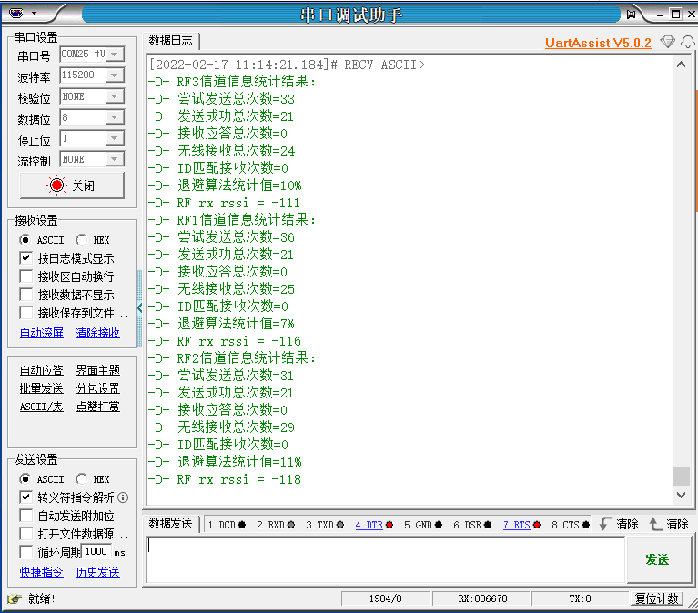
}The operation effect is as follows: