The specific principle of using the following structures needs to refer to LTDC-DMA2D liquid crystal display (I)
1, LTDC initialization structure
typedef struct
{
  uint32_t LTDC_HSPolarity;        	//Configure the polarity of the line synchronization signal HSYNC

  uint32_t LTDC_VSPolarity;        	//Configure the polarity of vertical synchronization signal VSYNC

  uint32_t LTDC_DEPolarity;        	//Configure the polarity of the data enable signal DE

  uint32_t LTDC_PCPolarity;        	//Configure the polarity of the pixel clock signal CLK

  uint32_t LTDC_HorizontalSync;    	//Configure the width of line synchronization signal HSYNC (HSW-1)

  uint32_t LTDC_VerticalSync;      	//Configure the width of vertical synchronization signal VSYNC (VSW-1)

  uint32_t LTDC_AccumulatedHBP;    	//Value of configuration (HSW+HBP-1)

  uint32_t LTDC_AccumulatedVBP;    	//Value of configuration (VSW+VBP-1)

  uint32_t LTDC_AccumulatedActiveW; //Value of configuration (HSW+HBP + effective width - 1)

  uint32_t LTDC_AccumulatedActiveH; //Value of configuration (VSW+VBP + effective height - 1)

  uint32_t LTDC_TotalWidth;     	//Value of configuration (HSW+HBP + effective width + HFP-1)

  uint32_t LTDC_TotalHeigh;     	//Value of configuration (VSW+VBP + effective height + HFP-1)

  uint32_t LTDC_BackgroundRedValue; //Configure red background value

  uint32_t LTDC_BackgroundGreenValue; //Configure green background value

   uint32_t LTDC_BackgroundBlueValue; //Configure blue background value
} LTDC_InitTypeDef;-
LTDC_HSPolarity
This member is used to set the polarity of the line synchronization signal HSYNC, that is, the level when HSYNC is valid. The value of this member can be set to high level (LTDC_HSPolarity_AH) or low level (LTDC_HSPolarity_AL).
-
LTDC_VSPolarity
This member is used to set the polarity of vertical synchronization signal VSYNC, which can be set to high level (LTDC_VSPolarity_AH) or low level (LTDC_VSPolarity_AL).
-
LTDC_DEPolarity
This member is used to set the polarity of the data enable signal DE, which can be set to high level (LTDC_DEPolarity_AH) or low level (LTDC_DEPolarity_AL).
-
LTDC_PCPolarity
This member is used to set the polarity of pixel clock signal CLK, which can be set as rising edge (LTDC_PCPolarity_IPC) or falling edge (LTDC_PCPolarity_IIPC), indicating when RGB data signal is collected in CLK.
-
LTDC_HorizontalSync
This member sets the width HSW of the line synchronization signal HSYNC, which takes the cycle of the pixel clock CLK as the unit. When actually writing this parameter (HSW-1), the parameter range is 0x000- 0xFFF.
-
LTDC_VerticalSync
This member sets the width VSW of the vertical synchronization signal VSYNC, which takes "line" as the bit. When actually writing this parameter, it should write (VSW-1), and the parameter range is 0x000- 0x7FF.
-
LTDC_AccumulatedHBP
This member is used to configure the cumulative value of "horizontal synchronous pixel HSW" plus "horizontal trailing edge pixel HBP". When actually writing this parameter, it should be written (HSW+HBP-1), and the parameter range is 0x000- 0xFFF.
-
LTDC_AccumulatedVBP
This member is used to configure the cumulative value of "vertical synchronization line VSW" plus "vertical trailing line VBP". When actually writing this parameter, it should be written (VSW+VBP-1), and the parameter range is 0x000- 0x7FF.
Time required for configuration:
-
LTDC_AccumulatedActiveW
This member is used to configure the cumulative value of "horizontal synchronous pixel HSW" plus "horizontal trailing edge pixel HBP" plus "effective pixel". When actually writing this parameter, it should be written (HSW+HBP + effective width - 1), and the parameter range is 0x000- 0xFFF.
-
LTDC_AccumulatedActiveH
This member is used to configure the cumulative value of "vertical synchronization line VSW" plus "vertical trailing line VBP" plus "effective line". When actually writing this parameter, it should be written (VSW+VBP + effective height - 1). The parameter range is 0x000- 0x7FF.
-
LTDC_TotalWidth
This member is used to configure the cumulative value of "horizontal synchronous pixel HSW" plus "horizontal trailing edge pixel HBP" plus "effective pixel" plus "horizontal leading edge pixel HFP", that is, the total width. When actually writing this parameter, it should be written (HSW+HBP + effective width + HFP-1), and the parameter range is 0x000- 0xFFF.
-
LTDC_TotalHeigh
This member is used to configure the cumulative value of "vertical synchronous line VSW" plus "vertical backward line VBP" plus "effective line" plus "vertical forward line VFP", that is, the total height. When actually writing this parameter, it should be written (HSW+HBP + effective height + VFP-1), and the parameter range is 0x000- 0x7FF
-
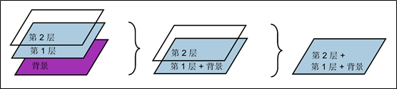
LTDC_BackgroundRedValue/GreenValue/ BlueValue
These three structure members are used to configure the color value of the background. The background layer mentioned here is a little different from the concept of "foreground layer / background layer" mentioned earlier. They correspond to "layer 2 / layer 1" in the figure below. In addition to these two layers, there is a final background layer. When the first and second layers are transparent, this background layer will be displayed, The background layer is a solid color rectangle, and its color value is configured by the three structure members. The parameter range of each member is 0x00- 0xFF.
After assigning the members of these LTDC initialization structures, the library function LTDC_ is called. Init can write these parameters into each configuration register of ltdc, and ltdc peripherals control the timing according to these configurations.
2, LTDC hierarchy initialization structure
The LTDC initialization structure only configures the basic timing of communication with the LCD screen, and many parameters such as pixel format and video memory address need to be completed by using the LTDC level initialization structure.
typedef struct
{
  uint32_t LTDC_HorizontalStart;      //Configure the starting line position of the window

  uint32_t LTDC_HorizontalStop;       //Configure the line end position of the window

  uint32_t LTDC_VerticalStart;        //Configure the vertical start position of the window

  uint32_t LTDC_VerticalStop;         //Configure the vertical beam position of the window

  uint32_t LTDC_PixelFormat;          //Configure the pixel format of the current layer

  uint32_t LTDC_ConstantAlpha;		  //Configure the transparency Alpha constant of the current layer

  uint32_t LTDC_DefaultColorBlue;     //Configure the default blue value of the current layer

  uint32_t LTDC_DefaultColorGreen;    //Configure the default green value for the current layer

  uint32_t LTDC_DefaultColorRed;	  //Configure the default red value of the current layer

  uint32_t LTDC_DefaultColorAlpha;    //Configure the default transparency value of the current layer

  uint32_t LTDC_BlendingFactor_1;     //Configuration mixing factor

  uint32_t LTDC_BlendingFactor_2;

  uint32_t LTDC_CFBStartAdress;      //Configure the starting position of the video memory of the current layer

  uint32_t LTDC_CFBLineLength;   	 //Configure the row data length of the current layer

  uint32_t LTDC_CFBPitch;            //Configures the increment from the beginning of a row to the beginning of pixels in the next row

  uint32_t LTDC_CFBLineNumber;       //Configure the number of rows in the current layer
} LTDC_Layer_InitTypeDef;
-
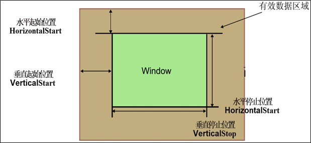
LTDC_ HorizontalStart /HorizontalStop/VerticalStart/VerticalStop
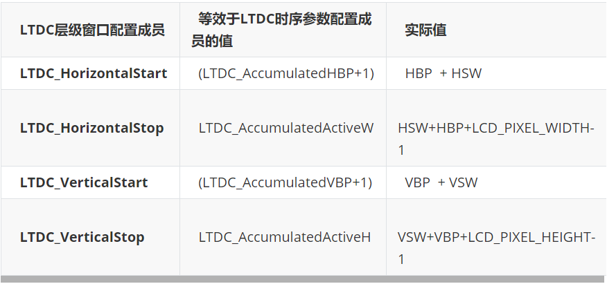
These members are used to determine the boundary of the display window of this layer, indicating the position of line start, line end, vertical start and vertical end respectively. Note that these parameters include the configuration of internal timing generator for synchronous HSW/VSW, trailing edge size HBP/VBP and effective data area. The values in the table are the values that should be written by each window configuration member.
| LTDC level window configuration member | Value equivalent to LTDC timing parameter configuration member | actual value |
|---|---|---|
| LTDC_HorizontalStart | (LTDC_AccumulatedHBP+1) | HBP + HSW |
| LTDC_HorizontalStop | LTDC_AccumulatedActiveW | HSW+HBP+LCD_PIXEL_WIDTH-1 |
| LTDC_VerticalStart | (LTDC_AccumulatedVBP+1) | VBP + VSW |
| LTDC_VerticalStop | LTDC_AccumulatedActiveH | VSW+VBP+LCD_PIXEL_HEIGHT-1 |
-
LTDC_PixelFormat
This member is used to set the pixel format of the layer data, which can be set as ltdc_ Pixelformat_ Argb8888 / rgb888 / rgb565 / arg1555 / argb4444 / L8 / al44 / al88 format. (if it's not transparent, the bottom layer doesn't make sense)
-
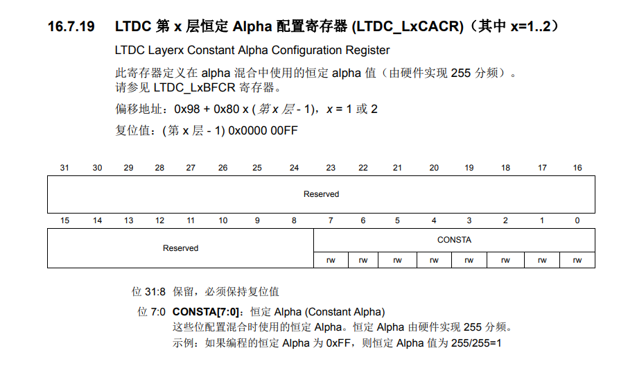
LTDC_ConstantAlpha
This member is used to set the constant transparency constant Alpha of the layer, which is called constant Alpha, and the parameter range is 0x00-0xFF. During layer mixing, you can choose whether to use only this constant Alpha for mixing operation or add the Alpha value of the pixel itself to the operation according to the configuration of the BlendingFactor member later.
-
LTDC_DefaultColorBlue/Green/Red/Alpha
These members are used to configure the default color values of the layer, namely blue, green, red and transparent components. The color is used outside the defined layer window or when the layer is prohibited.
-
LTDC_BlendingFactor_1/2
This member is used to set the mixing coefficients BF1 and BF2. The actual displayed color of each layer needs to use transparency to participate in the calculation, calculate the direct RGB color value without transparency, and then transmit it to the LCD (because the LCD itself has no concept of transparency). The calculation formula of mixing is:
BC = BF1 x C + BF2 x Cs
| parameter | explain | CA | PAxCA |
|---|---|---|---|
| BC | Color after mixing (mixing result) | - | - |
| C | Current layer color | - | - |
| Cs | Color of the bottom layer after mixing | - | - |
| BF1 | Mixing coefficient 1 | Equal to (constant Alpha value) | Equal to (constant Alpha x pixel Alpha value) |
| BF2 | Mixing coefficient 2 | Equal to (1-constant Alpha) | Equal to (1-constant Alpha x pixel Alpha value) |
Members of this structure can set whether BF1/BF2 parameters use CA configuration (LTDC_BlendingFactor1/2_CA) or PAxCA configuration (LTDC_BlendingFactor1/2_PAxCA). Configured as Ca means that the mixing coefficient only contains constant Alpha value, that is, the Alpha of the pixel itself will not affect the mixing effect (for example, the first layer and the background layer, we don't want to see the background layer). If configured as PAxCA, the mixing coefficient contains the Alpha value of the pixel itself, That is, the Alpha of the pixel itself is added to the mixing operation (for example, the second layer and the first layer, we want the first layer and the second layer to be mixed). The constant Alpha value is the transparency percentage of the previous "LTDC_ConstantAlpha" structure configuration parameter: (configured Alpha value / 0xFF).
Example: when mixing data sources, from bottom to top, if two layers are used, first mix the first layer with the LTDC background, and then use the mixed color to mix with the second layer to get the final result. For example, when only layer 1 data sources are used, and BF1 and BF2 are configured to use constant Alpha, the Alpha value is in LTDC_ The constant Alpha structure member value is configured as 240(0xF0). Therefore, the constant Alpha value is 240 / 255 = 0.94. If the current layer color C=128 and the background color Cs=48, the mixing result of the first layer and the background color is:
BC = constant Alpha x C + (1-constant Alpha) x Cs=0.94 x Cs +(1-0.94)x 48=123
-
LTDC_CFBStartAdress
This member is used to set the first address of the video memory of this layer, and the pixel data of this layer is saved in the storage space starting from this address.
-
LTDC_CFBLineLength
This member is used to set the row data length of the current layer, that is, the number of effective pixels per row x the number of bytes per pixel. When actually configuring this parameter, the value should be written (the number of effective pixels per row x the number of bytes per pixel + 3). The number of bytes per pixel is related to the pixel format. For example, RGB565 is 2 bytes, RGB888 is 3 bytes, and ARGB8888 is 4 bytes.
-
LTDC_CFBPitch
This member is used to set the data increment from the starting position of effective pixels in a row to the starting position of the next row. Without special circumstances, it is generally directly equal to the number of effective pixels in the row x the number of bytes of each pixel.
-
LTDC_CFBLineNumber
This member is used to set the number of display lines of the current layer.
Configure ltdc_ Layer_ After the InitTypeDef level initializes the structure, the library function LTDC_ is called. Layerinit can write these configurations into the level control register of ltdc to complete initialization. After initialization, ltdc will continuously transmit the data in the video memory space to the LCD for display. We can modify the data in the video memory directly or use DMA2D to change the display content.
3, DMA2D structure
typedef struct
{
  uint32_t DMA2D_Mode;                  //Configure the transmission mode of DMA2D

  uint32_t DMA2D_CMode;                 //Configure the color mode of DMA2D

  uint32_t DMA2D_OutputBlue;            //Configure the blue component of the output image

  uint32_t DMA2D_OutputGreen;           //Configure the green component of the output

  uint32_t DMA2D_OutputRed;             //Configure the red component of the output

  uint32_t DMA2D_OutputAlpha;           //Configure the transparency component of the output

  uint32_t DMA2D_OutputMemoryAdd;       //Configure video memory address

  uint32_t DMA2D_OutputOffset;          //Configure the offset of the output address

  uint32_t DMA2D_NumberOfLine;          //Configure how many rows to transfer

  uint32_t DMA2D_PixelPerLine;          //Configure how many pixels per row
} DMA2D_InitTypeDef;-
DMA2D_Mode
Used to configure the working mode of DMA2D, which can be set to the values in the following table:
| macro | explain |
|---|---|
| DMA2D_M2M | From memory to memory (FG get data source only) |
| DMA2D_M2M_PFC | Memory to memory and execute PFC (only FG acquisition when FG PFC is activated) |
| DMA2D_M2M_BLEND | Memory to memory and perform mixing (FG and BG acquisition when performing PFC and mixing) |
| DMA2D_R2M | Register to memory (no FG and BG, only output phase active) |
These working modes mainly distinguish the source of data, whether to enable PFC and whether to enable mixer.
If PFC is enabled, the data source in the memory will be converted and then transmitted to the video memory. If the mixer is enabled, DMA2D will mix the data from the two data sources and then output it to video memory.
If memory to memory mode is used, the library function dma2d needs to be called_ Fgconfig, using initialization structure DMA2D_FG_InitTypeDef configures the format, address and other parameters of the data source. (the background layer uses the function DMA2D_BGConfig and the structure DMA2D_BG_InitTypeDef).
-
DMA2D_CMode
This member is used to configure the output PFC color format of DMA2D, that is, the format it will be transmitted to video memory.
-
DMA2D_OutputBlue/ Green/ Red/ Alpha
These members are used to configure the register color value of DMA2D. If DMA2D works in "register to memory" (DMA2D_R2M) mode, this color value is used as the data source and copied by DMA2D to the video memory space, that is, the target space will be filled with this color.
-
DMA2D_OutputMemoryAdd
This member is used to configure the address of the output FIFO of DMA2D. The data of DMA2D will be transported to this space, which is generally set as the starting address of the display position of this transmission. (for transmitting line images)
-
DMA2D_OutputOffset
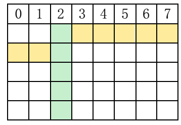
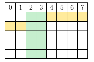
This member is used to configure the line offset (in pixels). The line offset will be added to the end of each line to determine the starting address of the next line. The Yellow grid in the following table indicates the row offset, and the green grid indicates the data to be displayed. A vertical line is shown in Table 1, and the width of the line is 1 pixel, so the value of row offset = 7-1 = 6, that is, "row offset value = row width - line width", the width of the line in Table 2 is 2 pixels, and the value of row offset = 7-2 = 5. (suitable for transmitting column images)
-
DMA2D_NumberOfLine
This member is used to configure how many rows of data DMA2D needs to transmit. There are five rows of data in the green part of Table 1.
-
DMA2D_PixelPerLine
This member is used to configure the number of pixels in each row, as shown in Table 2.
After configuring these structure members, call the library function DMA2D_Init can write these parameters into the control register of DMA2D, and then call DMA2D_ The starttransfer function starts data transfer and conversion.
4, Actual combat
(1) Drive SDRAM. It has been configured in the FMC section.
(2) Initialize LCD driver pin
(3) Using LTDC: two structures
(4) Directly control the display memory and control the LCD graphics
(5) Use DMA2D to quickly draw lines and rectangles
-
Initialize GPIO:
Because there are too many pins, only one pin can be selected as an example.
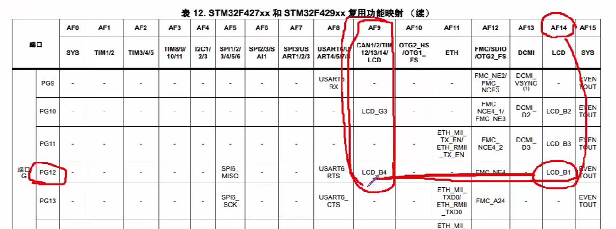
It should be noted that you need to take a good look at the data manual when configuring the pins.
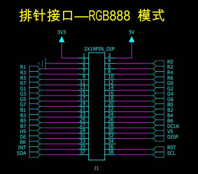
#define LTDC_R0_GPIO_PORT        	GPIOH
#define LTDC_R0_GPIO_CLK         	RCC_AHB1Periph_GPIOH
#define LTDC_R0_GPIO_PIN         	GPIO_Pin_2
#define LTDC_R0_PINSOURCE        	GPIO_PinSource2
#define LTDC_R0_AF			        GPIO_AF_LTDC

//The following two pins do not need to be multiplexed, but only need to control the input and output mode of their io port
/*LCD enable signal DISP, high level enable*/
#define LTDC_DISP_GPIO_PORT        GPIOD
#define LTDC_DISP_GPIO_CLK         RCC_AHB1Periph_GPIOD
#define LTDC_DISP_GPIO_PIN         GPIO_Pin_4
/*LCD backlight signal, high level enable*/
#define LTDC_BL_GPIO_PORT         GPIOD
#define LTDC_BL_GPIO_CLK          RCC_AHB1Periph_GPIOD
#define LTDC_BL_GPIO_PIN          GPIO_Pin_7
static void LCD_GPIO_Config(void)
{
 GPIO_InitTypeDef GPIO_InitStruct;

 /* Enable the pin clock used by the LCD */
                         //Red data line
 RCC_AHB1PeriphClockCmd(LTDC_R0_GPIO_CLK | LTDC_R1_GPIO_CLK | LTDC_R2_GPIO_CLK|
                        LTDC_R3_GPIO_CLK | LTDC_R4_GPIO_CLK | LTDC_R5_GPIO_CLK|
                        LTDC_R6_GPIO_CLK | LTDC_R7_GPIO_CLK |
                         //Green data line
                         LTDC_G0_GPIO_CLK|LTDC_G1_GPIO_CLK|LTDC_G2_GPIO_CLK|
                         LTDC_G3_GPIO_CLK|LTDC_G4_GPIO_CLK|LTDC_G5_GPIO_CLK|
                         LTDC_G6_GPIO_CLK|LTDC_G7_GPIO_CLK|
                         //Blue data line
                         LTDC_B0_GPIO_CLK|LTDC_B1_GPIO_CLK|LTDC_B2_GPIO_CLK|
                         LTDC_B3_GPIO_CLK|LTDC_B4_GPIO_CLK|LTDC_B5_GPIO_CLK|
                         LTDC_B6_GPIO_CLK|LTDC_B7_GPIO_CLK|
                         //Control signal line
                         LTDC_CLK_GPIO_CLK | LTDC_HSYNC_GPIO_CLK |LTDC_VSYNC_GPIO_CLK|
                         LTDC_DE_GPIO_CLK  | LTDC_BL_GPIO_CLK    |LTDC_DISP_GPIO_CLK ,ENABLE);


/* GPIO to configure */

/* Red data line */
 GPIO_InitStruct.GPIO_Pin = LTDC_R0_GPIO_PIN;
 GPIO_InitStruct.GPIO_Speed = GPIO_Speed_50MHz;
 GPIO_InitStruct.GPIO_Mode = GPIO_Mode_AF;
 GPIO_InitStruct.GPIO_OType = GPIO_OType_PP;
 GPIO_InitStruct.GPIO_PuPd = GPIO_PuPd_NOPULL;

 GPIO_Init(LTDC_R0_GPIO_PORT, &GPIO_InitStruct);
 GPIO_PinAFConfig(LTDC_R0_GPIO_PORT, LTDC_R0_PINSOURCE, LTDC_R0_AF);

 GPIO_InitStruct.GPIO_Pin = LTDC_R1_GPIO_PIN;
 GPIO_Init(LTDC_R1_GPIO_PORT, &GPIO_InitStruct);
 GPIO_PinAFConfig(LTDC_R1_GPIO_PORT, LTDC_R1_PINSOURCE, LTDC_R1_AF);

 GPIO_InitStruct.GPIO_Pin = LTDC_R2_GPIO_PIN;
 GPIO_Init(LTDC_R2_GPIO_PORT, &GPIO_InitStruct);
 GPIO_PinAFConfig(LTDC_R2_GPIO_PORT, LTDC_R2_PINSOURCE, LTDC_R2_AF);

 GPIO_InitStruct.GPIO_Pin = LTDC_R3_GPIO_PIN;
 GPIO_Init(LTDC_R3_GPIO_PORT, &GPIO_InitStruct);
 GPIO_PinAFConfig(LTDC_R3_GPIO_PORT, LTDC_R3_PINSOURCE, LTDC_R3_AF);

 GPIO_InitStruct.GPIO_Pin = LTDC_R4_GPIO_PIN;
 GPIO_Init(LTDC_R4_GPIO_PORT, &GPIO_InitStruct);
 GPIO_PinAFConfig(LTDC_R4_GPIO_PORT, LTDC_R4_PINSOURCE, LTDC_R4_AF);

 GPIO_InitStruct.GPIO_Pin = LTDC_R5_GPIO_PIN;
 GPIO_Init(LTDC_R5_GPIO_PORT, &GPIO_InitStruct);
 GPIO_PinAFConfig(LTDC_R5_GPIO_PORT, LTDC_R5_PINSOURCE, LTDC_R5_AF);

 GPIO_InitStruct.GPIO_Pin = LTDC_R6_GPIO_PIN;
 GPIO_Init(LTDC_R6_GPIO_PORT, &GPIO_InitStruct);
 GPIO_PinAFConfig(LTDC_R6_GPIO_PORT, LTDC_R6_PINSOURCE, LTDC_R6_AF);

 GPIO_InitStruct.GPIO_Pin = LTDC_R7_GPIO_PIN;
 GPIO_Init(LTDC_R7_GPIO_PORT, &GPIO_InitStruct);
 GPIO_PinAFConfig(LTDC_R7_GPIO_PORT, LTDC_R7_PINSOURCE, LTDC_R7_AF);

 //Green data line
 GPIO_InitStruct.GPIO_Pin = LTDC_G0_GPIO_PIN;
 GPIO_Init(LTDC_G0_GPIO_PORT, &GPIO_InitStruct);
 GPIO_PinAFConfig(LTDC_G0_GPIO_PORT, LTDC_G0_PINSOURCE, LTDC_G0_AF);

 GPIO_InitStruct.GPIO_Pin = LTDC_G1_GPIO_PIN;
 GPIO_Init(LTDC_G1_GPIO_PORT, &GPIO_InitStruct);
 GPIO_PinAFConfig(LTDC_G1_GPIO_PORT, LTDC_G1_PINSOURCE, LTDC_G1_AF);

 GPIO_InitStruct.GPIO_Pin = LTDC_G2_GPIO_PIN;
 GPIO_Init(LTDC_G2_GPIO_PORT, &GPIO_InitStruct);
 GPIO_PinAFConfig(LTDC_G2_GPIO_PORT, LTDC_G2_PINSOURCE, LTDC_G2_AF);

 GPIO_InitStruct.GPIO_Pin = LTDC_G3_GPIO_PIN;
 GPIO_Init(LTDC_G3_GPIO_PORT, &GPIO_InitStruct);
 GPIO_PinAFConfig(LTDC_G3_GPIO_PORT, LTDC_G3_PINSOURCE, LTDC_G3_AF);

 GPIO_InitStruct.GPIO_Pin = LTDC_G4_GPIO_PIN;
 GPIO_Init(LTDC_G4_GPIO_PORT, &GPIO_InitStruct);
 GPIO_PinAFConfig(LTDC_G4_GPIO_PORT, LTDC_G4_PINSOURCE, LTDC_G4_AF);

 GPIO_InitStruct.GPIO_Pin = LTDC_G5_GPIO_PIN;
 GPIO_Init(LTDC_G5_GPIO_PORT, &GPIO_InitStruct);
 GPIO_PinAFConfig(LTDC_G5_GPIO_PORT, LTDC_G5_PINSOURCE, LTDC_G5_AF);

 GPIO_InitStruct.GPIO_Pin = LTDC_G6_GPIO_PIN;
 GPIO_Init(LTDC_G6_GPIO_PORT, &GPIO_InitStruct);
 GPIO_PinAFConfig(LTDC_G6_GPIO_PORT, LTDC_G6_PINSOURCE, LTDC_G6_AF);

 GPIO_InitStruct.GPIO_Pin = LTDC_G7_GPIO_PIN;
 GPIO_Init(LTDC_G7_GPIO_PORT, &GPIO_InitStruct);
 GPIO_PinAFConfig(LTDC_G7_GPIO_PORT, LTDC_G7_PINSOURCE, LTDC_G7_AF);

 //Blue data line
 GPIO_InitStruct.GPIO_Pin = LTDC_B0_GPIO_PIN;
 GPIO_Init(LTDC_B0_GPIO_PORT, &GPIO_InitStruct);
 GPIO_PinAFConfig(LTDC_B0_GPIO_PORT, LTDC_B0_PINSOURCE, LTDC_B0_AF);

 GPIO_InitStruct.GPIO_Pin = LTDC_B1_GPIO_PIN;
 GPIO_Init(LTDC_B1_GPIO_PORT, &GPIO_InitStruct);
 GPIO_PinAFConfig(LTDC_B1_GPIO_PORT, LTDC_B1_PINSOURCE, LTDC_B1_AF);

 GPIO_InitStruct.GPIO_Pin = LTDC_B2_GPIO_PIN;
 GPIO_Init(LTDC_B2_GPIO_PORT, &GPIO_InitStruct);
 GPIO_PinAFConfig(LTDC_B2_GPIO_PORT, LTDC_B2_PINSOURCE, LTDC_B2_AF);

 GPIO_InitStruct.GPIO_Pin = LTDC_B3_GPIO_PIN;
 GPIO_Init(LTDC_B3_GPIO_PORT, &GPIO_InitStruct);
 GPIO_PinAFConfig(LTDC_B3_GPIO_PORT, LTDC_B3_PINSOURCE, LTDC_B3_AF);

 GPIO_InitStruct.GPIO_Pin = LTDC_B4_GPIO_PIN;
 GPIO_Init(LTDC_B4_GPIO_PORT, &GPIO_InitStruct);
 GPIO_PinAFConfig(LTDC_B4_GPIO_PORT, LTDC_B4_PINSOURCE, LTDC_B4_AF);

 GPIO_InitStruct.GPIO_Pin = LTDC_B5_GPIO_PIN;
 GPIO_Init(LTDC_B5_GPIO_PORT, &GPIO_InitStruct);
 GPIO_PinAFConfig(LTDC_B5_GPIO_PORT, LTDC_B5_PINSOURCE, LTDC_B5_AF);

 GPIO_InitStruct.GPIO_Pin = LTDC_B6_GPIO_PIN;
 GPIO_Init(LTDC_B6_GPIO_PORT, &GPIO_InitStruct);
 GPIO_PinAFConfig(LTDC_B6_GPIO_PORT, LTDC_B6_PINSOURCE, LTDC_B6_AF);

 GPIO_InitStruct.GPIO_Pin = LTDC_B7_GPIO_PIN;
 GPIO_Init(LTDC_B7_GPIO_PORT, &GPIO_InitStruct);
 GPIO_PinAFConfig(LTDC_B7_GPIO_PORT, LTDC_B7_PINSOURCE, LTDC_B7_AF);

 //Control signal line
 GPIO_InitStruct.GPIO_Pin = LTDC_CLK_GPIO_PIN;
 GPIO_Init(LTDC_CLK_GPIO_PORT, &GPIO_InitStruct);
 GPIO_PinAFConfig(LTDC_CLK_GPIO_PORT, LTDC_CLK_PINSOURCE, LTDC_CLK_AF);

 GPIO_InitStruct.GPIO_Pin = LTDC_HSYNC_GPIO_PIN;
 GPIO_Init(LTDC_HSYNC_GPIO_PORT, &GPIO_InitStruct);
 GPIO_PinAFConfig(LTDC_HSYNC_GPIO_PORT, LTDC_HSYNC_PINSOURCE, LTDC_HSYNC_AF);

 GPIO_InitStruct.GPIO_Pin = LTDC_VSYNC_GPIO_PIN;
 GPIO_Init(LTDC_VSYNC_GPIO_PORT, &GPIO_InitStruct);
 GPIO_PinAFConfig(LTDC_VSYNC_GPIO_PORT, LTDC_VSYNC_PINSOURCE, LTDC_VSYNC_AF);

 GPIO_InitStruct.GPIO_Pin = LTDC_DE_GPIO_PIN;
 GPIO_Init(LTDC_DE_GPIO_PORT, &GPIO_InitStruct);
 GPIO_PinAFConfig(LTDC_DE_GPIO_PORT, LTDC_DE_PINSOURCE, LTDC_DE_AF);

 //BL DISP
 GPIO_InitStruct.GPIO_Pin = LTDC_DISP_GPIO_PIN;
 GPIO_InitStruct.GPIO_Speed = GPIO_Speed_50MHz;
 GPIO_InitStruct.GPIO_Mode = GPIO_Mode_OUT;
 GPIO_InitStruct.GPIO_OType = GPIO_OType_PP;
 GPIO_InitStruct.GPIO_PuPd = GPIO_PuPd_UP;

 GPIO_Init(LTDC_DISP_GPIO_PORT, &GPIO_InitStruct);


 GPIO_InitStruct.GPIO_Pin = LTDC_BL_GPIO_PIN;
 GPIO_Init(LTDC_BL_GPIO_PORT, &GPIO_InitStruct);

 //Pull up enable lcd
 GPIO_SetBits(LTDC_DISP_GPIO_PORT,LTDC_DISP_GPIO_PIN);		//Display switch
 GPIO_SetBits(LTDC_BL_GPIO_PORT,LTDC_BL_GPIO_PIN);			//Drive backlight
} -
Initialize the LTDC structure and configure the control parameters of the LCD:
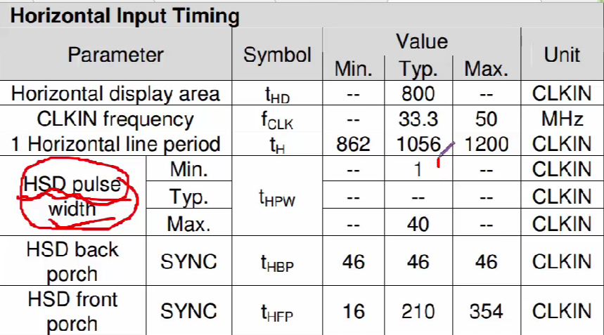
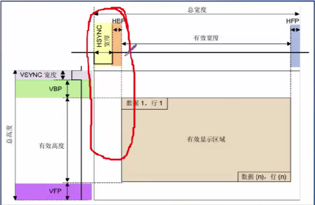
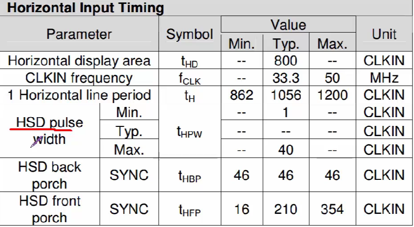
It can be seen from the figure that HSYNC is effective at low level, so low level is configured.
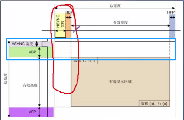
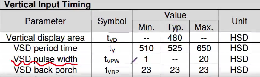
From the figure, VSYNC should also be effective at low level:
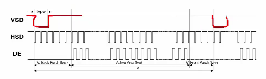
HSD width can be obtained from the following figure:
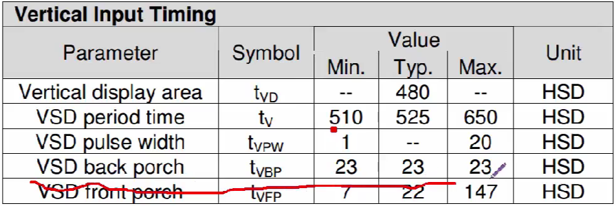
 Similarly, for VSD:
Finally, the parameters to be defined are as follows:
/*According to the parameter configuration of LCD data manual*/
#define HBP  46 		// Invalid pixel after HSYNC
#define VBP  23 		// Number of invalid rows after VSYNC

#define HSW   1 		// HSYNC width
#define VSW   1 		// VSYNC width

#define HFP  20 		// Invalid pixel before HSYNC
#define VFP   22 	// Invalid number of rows before VSYNC
Clock required for LTDC initialization:

The clock output to LTDC is PLLSAI.
You need to use the following function for configuration:
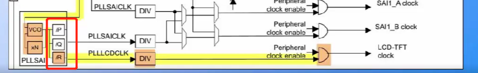
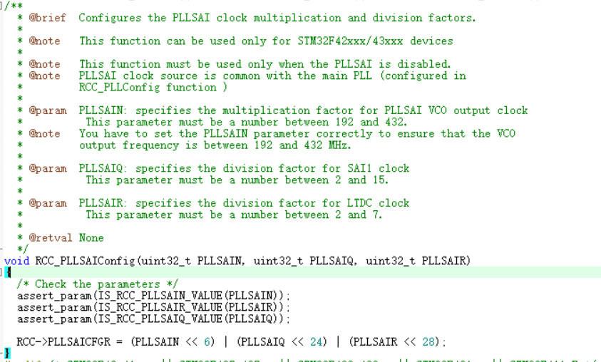
For example, if we need to configure a 24Mhz clock here, then 24MHz * DIV * R = N, where DIV is set to 4 frequency division.
LTDC structure initialization:
void LCD_Init(void)
{
LTDC_InitTypeDef LTDC_InitStruct;
/* Enable LTDC peripheral clock */
RCC_APB2PeriphClockCmd(RCC_APB2Periph_LTDC, ENABLE);
/* Enable DMA2D clock */
RCC_AHB1PeriphClockCmd(RCC_AHB1Periph_DMA2D, ENABLE);
/* Initialize the control pin of LCD */
LCD_GPIO_Config();
/* Initialize SDRAM so that SDRAM can be used as video memory */
SDRAM_Init();
/* Configure PLLSAI frequency divider, whose output is used as pixel synchronization clock CLK*/
/* PLLSAI_VCO Input clock = HSE_VALUE/PLL_M = 1 Mhz */
/* PLLSAI_VCO Output clock = PLLSAI_VCO input * PLLSAI_N = 416 Mhz */
/* PLLLCDCLK = PLLSAI_VCO Output / PLLSAI_R = 420/6 Mhz */
/* LTDC Clock frequency = PLLLCDCLK / DIV = 420/6/8 = 8.75 Mhz */
/* LTDC If the clock is too high, the flower screen will be guided. If the requirements for screen brushing speed are not high, reducing the clock frequency can reduce the flower screen phenomenon*/
/* The three parameters of the following function are: pllsain, PLLSAIQ and pllsair, where PLLSAIQ is independent of LTDC*/
RCC_PLLSAIConfig(420,7, 6);
/*The parameters of the following functions are DIV values*/
RCC_LTDCCLKDivConfig(RCC_PLLSAIDivR_Div8);
/* Enable PLLSAI clock */
RCC_PLLSAICmd(ENABLE);
/* Wait for PLLSAI initialization to complete */
while(RCC_GetFlagStatus(RCC_FLAG_PLLSAIRDY) == RESET)
{}
/* LTDC Disposition*********************************************************/
/*Signal polarity configuration*/
/* Row synchronization signal polarity */
LTDC_InitStruct.LTDC_HSPolarity = LTDC_HSPolarity_AL;
/* Vertical synchronization signal polarity */
LTDC_InitStruct.LTDC_VSPolarity = LTDC_VSPolarity_AL;
/* Data enable signal polarity */
LTDC_InitStruct.LTDC_DEPolarity = LTDC_DEPolarity_AL;
/* Pixel synchronization clock polarity */
LTDC_InitStruct.LTDC_PCPolarity = LTDC_PCPolarity_IPC;
/* Configure LCD background color */
LTDC_InitStruct.LTDC_BackgroundRedValue = 0;
LTDC_InitStruct.LTDC_BackgroundGreenValue = 0;
LTDC_InitStruct.LTDC_BackgroundBlueValue = 0;
/* Time parameter configuration */
/* Configure line synchronization signal width (HSW-1) */
LTDC_InitStruct.LTDC_HorizontalSync =HSW-1;
/* Configure vertical sync signal width (VSW-1) */
LTDC_InitStruct.LTDC_VerticalSync = VSW-1;
/* Configuration (HSW+HBP-1) */
LTDC_InitStruct.LTDC_AccumulatedHBP =HSW+HBP-1;
/* Configuration (VSW+VBP-1) */
LTDC_InitStruct.LTDC_AccumulatedVBP = VSW+VBP-1;
/* Configuration (HSW+HBP + effective pixel width - 1) */
LTDC_InitStruct.LTDC_AccumulatedActiveW = HSW+HBP+LCD_PIXEL_WIDTH-1;
/* Configuration (VSW+VBP + effective pixel height - 1) */
LTDC_InitStruct.LTDC_AccumulatedActiveH = VSW+VBP+LCD_PIXEL_HEIGHT-1;
/* Total configured width (HSW+HBP + effective pixel width + HFP-1) */
LTDC_InitStruct.LTDC_TotalWidth =HSW+ HBP+LCD_PIXEL_WIDTH + HFP-1;
/* Total configured height (VSW+VBP + effective pixel height + VFP-1) */
LTDC_InitStruct.LTDC_TotalHeigh =VSW+ VBP+LCD_PIXEL_HEIGHT + VFP-1;
LTDC_Init(<DC_InitStruct);
LTDC_Cmd(ENABLE);
} -
Initialize LTDC level
Initialize the first layer (bottom layer):
We configure according to the table mentioned above:
When configuring Alpha, it should be noted that ltdc should be set in the configuration register_ In lxcarc:
For configuring colors:
If the transparency of our pixels is all transparent, that is, Alpha=0, we can get
BC = (1 * 0) * the color of layer2 + (1-1 * 0) * the color of layer1
Finally, the transparent color of layer 2 can be combined with the background color of layer 1.
void LCD_LayerInit(void)
{
LTDC_Layer_InitTypeDef LTDC_Layer_InitStruct;
/* Layer window configuration */
/* Configure the window boundary of this layer. Note that these parameters include HBP HSW VBP VSW */
//The first starting pixel of a row, and the member value is applied as the value of (ltdc_initstruct. Ltdc_accumulated HBP + 1)
LTDC_Layer_InitStruct.LTDC_HorizontalStart = HBP + HSW;
//The last pixel in a row. The member value is applied as the value of (LTDC_InitStruct.LTDC_AccumulatedActiveW)
LTDC_Layer_InitStruct.LTDC_HorizontalStop = HSW+HBP+LCD_PIXEL_WIDTH-1;
//The first starting pixel of a column. The member value is applied as the value of (ltdc_initstruct. Ltdc_accumulated VBP + 1)
LTDC_Layer_InitStruct.LTDC_VerticalStart = VBP + VSW;
//The last pixel of a column. The member value is applied as the value of (LTDC_InitStruct.LTDC_AccumulatedActiveH)
LTDC_Layer_InitStruct.LTDC_VerticalStop = VSW+VBP+LCD_PIXEL_HEIGHT-1;
/* Pixel format configuration*/
LTDC_Layer_InitStruct.LTDC_PixelFormat = LTDC_Pixelformat_RGB888;
/* Constant Alpha value configuration, 0-255 */
LTDC_Layer_InitStruct.LTDC_ConstantAlpha = 255;
/* The default background color, which is used outside the defined layer window or when the layer is disabled. This is equivalent to the bottom floor */
LTDC_Layer_InitStruct.LTDC_DefaultColorBlue = 0xFF;
LTDC_Layer_InitStruct.LTDC_DefaultColorGreen = 0xFF;
LTDC_Layer_InitStruct.LTDC_DefaultColorRed = 0xFF;
LTDC_Layer_InitStruct.LTDC_DefaultColorAlpha = 0xFF;
/* Configure the blend factor CA to use a constant Alpha value, PAxCA to use a pixel Alpha x constant Alpha value */
LTDC_Layer_InitStruct.LTDC_BlendingFactor_1 = LTDC_BlendingFactor1_CA; //1
LTDC_Layer_InitStruct.LTDC_BlendingFactor_2 = LTDC_BlendingFactor2_PAxCA;//2
/* The member should write (bytes occupied by one row of pixel data + 3)
Line Lenth = Number of effective pixels in a row x number of bytes per pixel + 3
Number of effective pixels in a row = LCD_PIXEL_WIDTH
Bytes per pixel = 2 (RGB565/RGB1555) / 3 (RGB888)/ 4 (ARGB8888)
*/
LTDC_Layer_InitStruct.LTDC_CFBLineLength = ((LCD_PIXEL_WIDTH * 3) + 3);
/* The pixel increment from the start of a row to the start of the next row
Pitch = Number of effective pixels in a row x number of bytes per pixel */
LTDC_Layer_InitStruct.LTDC_CFBPitch = (LCD_PIXEL_WIDTH * 3);
/* Configure the number of valid rows */
LTDC_Layer_InitStruct.LTDC_CFBLineNumber = LCD_PIXEL_HEIGHT;
/* Configure the first address of video memory of this layer */
LTDC_Layer_InitStruct.LTDC_CFBStartAdress = LCD_FRAME_BUFFER;
/* Initialize layer 1 with the above configuration*/
LTDC_LayerInit(LTDC_Layer1, <DC_Layer_InitStruct);
/*Configure layer 2. If the value of a member is not overridden, the member will use the same configuration as layer 1 */
/* Configure the first address of video memory of this layer, which is next to the back of layer 1*/
LTDC_Layer_InitStruct.LTDC_CFBStartAdress = LCD_FRAME_BUFFER + BUFFER_OFFSET;
/* Configure the mixing factor and use pixel Alpha to participate in the mixing */
LTDC_Layer_InitStruct.LTDC_BlendingFactor_1 = LTDC_BlendingFactor1_PAxCA;
LTDC_Layer_InitStruct.LTDC_BlendingFactor_2 = LTDC_BlendingFactor2_PAxCA;
/* Initialize layer 2 */
LTDC_LayerInit(LTDC_Layer2, <DC_Layer_InitStruct);
/* Reload configuration now */
LTDC_ReloadConfig(LTDC_IMReload);
/*Enable foreground and background layers */
LTDC_LayerCmd(LTDC_Layer1, ENABLE);
LTDC_LayerCmd(LTDC_Layer2, ENABLE);
/* Reload configuration now */
LTDC_ReloadConfig(LTDC_IMReload);
/* Set font (English) */
LCD_SetFont(&LCD_DEFAULT_FONT);
}For the addresses of the first and second layers to be put into the SDRAM memory, we can specify:
#define LCD_WIDTH   800
#define LCD_HEIGHT  480

//First address of layer 1 video memory, first address of SDRAM
#define LCD_LAYER1_START_ADDR   0xD0000000
#define LCD_LAYER1_BUFFER_SIZE  LCD_WIDTH * LCD_HEIGHT * 2

//First address of layer 2 video memory
#define LCD_LAYER2_START_ADDR   (LCD_LAYER1_START_ADDR + LCD_LAYER1_BUFFER_SIZE)
#define LCD_LAYER2_BUFFER_SIZE  LCD_WIDTH * LCD_HEIGHT * 4
Write an underlined function:
void DIS_Line(void)
{
	uint16_t i;
    uint32_t *p = (uint32_t *)(LCD_LAYER2_START_ADDR + LCD_WIDTH * 20 * 4)
    for(i=0;i<800;i++)
    {
        *p = 0xffff0000;//Draw a red line
        p++;
    }
}-
Using dma2d (can reduce the burden of CPU)
Remember to initialize the clock when using DMA2D:
RCC_AHB1PeriphClockCmd (RCC_AHB1Periph_DMA2D,ENABLE);
Use DMA2D to display a solid color image on the second layer:
void DMA2D_DIS(void)
{
    DMA2D_InitTypeDef DMA2D_InitTypeStruct;

    //Register to memory
    DMA2D_InitTypeStruct.DMA2D_Mode = DMA2D_R2M;
    //Layer 2 image format
    DMA2D_InitTypeStruct.DMA2D_CMode = DMA2D_ARGB8888;
    //The color value you want to transfer
    DMA2D_InitTypeStruct.DMA2D_OutputRed = 0xff;
    DMA2D_InitTypeStruct.DMA2D_OutputGreen = 0x00;
    DMA2D_InitTypeStruct.DMA2D_OutputBlue = 0x00;
    DMA2D_InitTypeStruct.DMA2D_OutputAlpha = 0xff;

    //Video memory address to transfer to
    DMA2D_InitTypeStruct.DMA2D_OutputMemoryAdd = LCD_LAYER2_START_ADDR;
    /*When it needs to be displayed in other lines, it can be modified as follows:
     DMA2D_InitTypeStruct.DMA2D_OutputMemoryAdd = LCD_LAYER2_START_ADDR + LCD_Width * 20 * 4 + 350 * 4;
     //It means moving down 20 lines of display. Because each pixel occupies four bytes, multiply by 4. The following display 350 refers to the display in column 350
    */
    //No row offset is required
    DMA2D_InitTypeStruct.DMA2D_OutputOffset = 0;
    //Full screen display
    DMA2D_InitTypeStruct.DMA2D_PixelPerLine = 800;
    DMA2D_InitTypeStruct.DMA2D_NumberOfLine = 480;

    /*If you want to display a rectangle
     DMA2D_InitTypeStruct.DMA2D_OutputOffset = 800-300;
     DMA2D_InitTypeStruct.DMA2D_PixelPerLine = 300;	//that 's ok
     DMA2D_InitTypeStruct.DMA2D_NumberOfLine = 200; //column
    */

    DMA2D_Init(&DMA2D_InitTypeStruct);

    DMA2D_StartTransfer();

    while(DMA2D_GetFlagStatus(DMA2D_FLAG_TC)==RESET)
    {
        //Here you can go back to the CPU to execute other things.
    }

}
The principle of drawing horizontal lines is similar. It is basically operating pixels:
//Draw a straight line with DMA2D
void DIS_Line_DMA2D(void)
{
  DMA2D_InitTypeDef  DMA2D_InitTypeStruct;

  DMA2D_InitTypeStruct.DMA2D_Mode = DMA2D_R2M ;
  DMA2D_InitTypeStruct.DMA2D_CMode = DMA2D_ARGB8888;

  //Color value to transfer
  DMA2D_InitTypeStruct.DMA2D_OutputRed = 0xff;
  DMA2D_InitTypeStruct.DMA2D_OutputGreen = 0x00;
  DMA2D_InitTypeStruct.DMA2D_OutputBlue = 0x00;
  DMA2D_InitTypeStruct.DMA2D_OutputAlpha = 0xff;

  //Video memory address to transfer to
  DMA2D_InitTypeStruct.DMA2D_OutputMemoryAdd = LCD_LAYER2_START_ADDR +LCD_WIDTH*20*4 + 350*4;
  DMA2D_InitTypeStruct.DMA2D_OutputOffset = 800-1;
  DMA2D_InitTypeStruct.DMA2D_PixelPerLine = 1;
  DMA2D_InitTypeStruct.DMA2D_NumberOfLine = 200;

  DMA2D_Init(&DMA2D_InitTypeStruct);

  DMA2D_StartTransfer();

  while( DMA2D_GetFlagStatus(DMA2D_FLAG_TC) ==RESET);
}
Use DMA2D to process the first layer (bottom layer):
The image of the first layer is normally RGB565 or RGB888. Now take RGB565 as an example:
void DIS_RECT_LAYER1(void)
{
  DMA2D_InitTypeDef  DMA2D_InitTypeStruct;

  DMA2D_InitTypeStruct.DMA2D_Mode = DMA2D_R2M ;
  DMA2D_InitTypeStruct.DMA2D_CMode = DMA2D_RGB565;


//Color value to transfer
DMA2D_InitTypeStruct.DMA2D_OutputRed = (0xff >>3) & 0x1F ; //Convert 8-bit color value to 5-bit color value
DMA2D_InitTypeStruct.DMA2D_OutputGreen = (0xFF>>2) & 0x3F ;//Convert 8-bit color value to 6-bit color value
DMA2D_InitTypeStruct.DMA2D_OutputBlue = (0x00 >>3) & 0x1F;  //Convert 8-bit color value to 5-bit color value
DMA2D_InitTypeStruct.DMA2D_OutputAlpha = 0xff;

  //Video memory address to transfer to
  DMA2D_InitTypeStruct.DMA2D_OutputMemoryAdd = LCD_LAYER1_START_ADDR +LCD_WIDTH*200*2 + 350*2;
  DMA2D_InitTypeStruct.DMA2D_OutputOffset = 800-100;
  DMA2D_InitTypeStruct.DMA2D_PixelPerLine = 100;
  DMA2D_InitTypeStruct.DMA2D_NumberOfLine = 100;

  DMA2D_Init(&DMA2D_InitTypeStruct);

  DMA2D_StartTransfer();

  while( DMA2D_GetFlagStatus(DMA2D_FLAG_TC) ==RESET);

}