Article directory
- Preface:
- 1, Overview of enterprise cluster application
- 1.1 basic overview of cluster
- 1.2 enterprise cluster classification
- 1.3 analysis of load balancing cluster working mode
- IP Tunnel
- 1.4 load balancing cluster architecture
- 1.53 about LVS virtual server
- 2, LVS load balancing experiment
- 2.1 configuration environment
- 2.2 configure NFS server
- 2.2.1 add disk, partition and format
- 2.2.2 create mount point and set auto mount
- 2.2.3 shared storage space
- 2.2.4 modify network card
- 2.3 configure web node server
- 2.4 configure LVS server
- 2.5 setting up firewall
- 2.6 load LVS scheduling module and define script
- 2.7 verification results
- Conclusion:
Preface:
Scalable network services involve several different structures, all of which require a front-end load scheduler (or multiple master-slave backups).
The principle of LVS will run through all load balancing services. The processing mechanisms of LVS mainly include: the unique access to requests, scheduling and allocation according to the state of the server (with scheduling algorithm), and health check for all the back-end servers.
1, Overview of enterprise cluster application
1.1 basic overview of cluster
-
Cluster, cluster, cluster
-
It is composed of multiple hosts, but it is a whole
In the Internet application, with the increasing requirements of the site for hardware performance, response speed, service stability, data reliability and so on, a single server is unable to meet the requirements
-
Solution
Using expensive minicomputers and mainframes
Building a service cluster with a normal server
1.2 enterprise cluster classification
-
According to the target differences of the cluster, it can be divided into three types:
Load Balance Cluster
Highly available cluster
High performance cluster
High availability cluster (high reliability): two schedulers, one for main and one for standby, are grouped in groups, and the two schedulers may not be in the same place
High performance computing cluster: with more than one CPU/GPU and all hardware for computing (computing power) storage, bandwidth, memory, cpu and other computable performance is called computing power. The set of servers with the above functions is computing cluster
-
Load Balance Cluster
In order to improve the response ability of the application system, handle more access requests as much as possible, and reduce latency, the overall performance of high concurrency and high load (LB) is achieved
The load distribution of LB depends on the shunting algorithm of the master node
-
High Availability Cluster
In order to improve the reliability of the application system and reduce the interruption time as much as possible, ensure the continuity of service and achieve the fault-tolerant effect of high availability (HA)
HA works in two modes: duplex mode and master-slave mode
-
High Performancd Computer Cluster
In order to improve the CPU operation speed, expand the hardware resources and analysis ability of the application system, the high performance computing (HPC) ability of quite large-scale and supercomputer is obtained
The high performance of high-performance computing cluster depends on "distributed computing" and "parallel computing". Through the software of special hardware, the CPU, memory and other resources of multiple servers are integrated together to achieve the computing ability only large-scale and supercomputer can have
HA: high availability
Duplex: two servers / schedulers are in a flat state. When the service comes, both servers can handle (decentralized mechanism) the level relationship between servers in the cluster
Master Slave: two servers, one master, one slave or more slaves. There is a master-slave relationship in the cluster, which is called the centralization mechanism
Case of decentralization mechanism: redis cluster (typical)
High performance computing cluster instance: in the logical sense of "cloud", it is similar to the way LVM forms volume groups.
1.3 analysis of load balancing cluster working mode
-
Load balancing cluster is the most commonly used cluster type in Enterprises
-
There are three working modes of cluster load scheduling technology
Address translation
IP tunnel
Direct routing
1.3.1 NAT mode
-
Network Address Translation
It is called NAT mode for short, which is similar to the private network structure of firewall. As the gateway of index server node, load scheduler serves as the access entrance of client and the access exit of each node responding to client
The server node uses private IP address, which is located in the same physical network as the load scheduler. The security is better than the other two ways
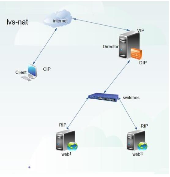
The server in the middle is the gateway (as a software firewall)
This server uses the internal port as the internal gateway and the external port as the external gateway, so it needs to turn on the routing function
When transmitting data from the intranet to the Internet, IP mapping (conversion) is needed to map to the public address.
At the same time, the internal server is dispatched and allocated to one of the last two services according to the request
The export and import, dispatching and distribution, address conversion, routing function, etc. are all completed by the LVS server.
Of course, for the current network environment, we will add a hardware firewall to the external port of this server to enhance security, and add a traffic cleaning server.
1.3.2 TUN mode
-
IP Tunnel
It is called TUN mode for short. The open network structure is adopted. The load scheduler is only the access of the client, and each node directly responds to the client through its own internet connection instead of passing through the load scheduler
Server nodes are scattered in different locations of the Internet, with independent public IP addresses, and communicate with the load scheduler through a dedicated IP tunnel
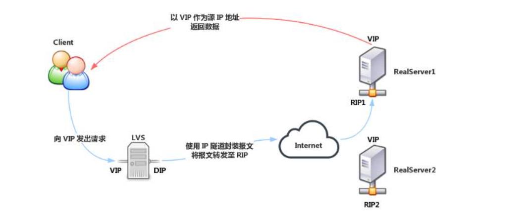
The server nodes are scattered in different locations in the Internet, with independent public IP addresses, and communicate with the load scheduler through the private IP tunnel (VPN)
VPN implements double encryption:
① Tunnel encryption
② Data encryption
VPN can be used in both private and public networks
All servers of IP tunnel are in public network mode
1.3.3 DR mode
-
Direct Routing
DR mode is short for short. It adopts semi open network structure, similar to TUN mode, but each node is not scattered around, but is located in the same physical network with the scheduler
The load scheduler is connected with each node server through the local network without establishing a dedicated IP tunnel
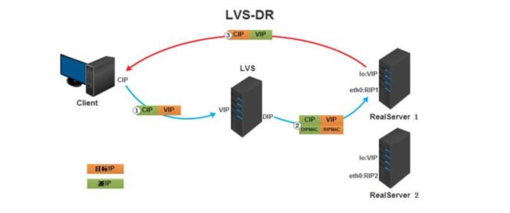
DR mode exists in private network, and all servers use private IP
It is responsible for the connection between the dispatcher and each node server through the local network, and does not need to establish a dedicated IP tunnel
Add: the SLB scheduler used by Ali is SLB
SLB includes LVS and Tengine (based on nginx function development)
LVS controls four layers (transport layer), i.e. IP and port
Tengine controlled layer 7 (application layer such as HTTP HTTPS)
Therefore, SLB controls four and seven layers, with high security
-
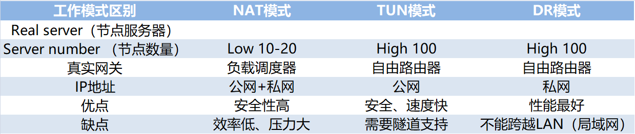
Summary: differences of three working modes
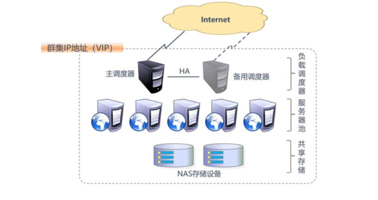
1.4 load balancing cluster architecture
-
Structure of load balancing
First layer, Load Balancer or Director
Second time, Server Pool
Third, Share Storage
-
Structure of load balancing
1.53 about LVS virtual server
1.5.1 LVS load scheduling algorithm
-
Round Robin
Assign the received access requests to each node in the cluster (real server) in turn
Treat each server equally, regardless of the actual number of connections and system load of the server
-
Weighted Round Robin
According to the real server's processing power, the received access requests are allocated in turn. The scheduler can automatically query the load of each node and dynamically adjust its weight (manual allocation)
Ensure that the server with strong processing capacity bears more access traffic
-
Least Connections
According to the number of established connections of the real server, the access requests received are assigned to the nodes with the least number of connections in priority
-
Weighted Least Connections
In the case of large performance difference between server nodes, the weight can be adjusted automatically for the real server
Nodes with higher weight will bear a larger proportion of active connection load
1.5.2 ipvsadm tools
- LVS cluster creation and management
2, LVS load balancing experiment
Environment: prepare 5 virtual machines, including 4 centos 7 and 1 win10 (client). This experiment is conducted in the host only mode of virtual machines (after the installation of the installation package, start the host only mode
Positioning: the first one in centos 7-4 is used as LVS scheduler + firewall, CentOS 7-5 and CentOS 7-6 are used as web servers, and CentOS 7-7 is used as NFS to provide storage (two hard disks are added)
2.1 configuration environment
Experimental topology: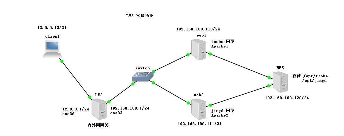
2.2 configure NFS server
2.2.1 add disk, partition and format
Add disk: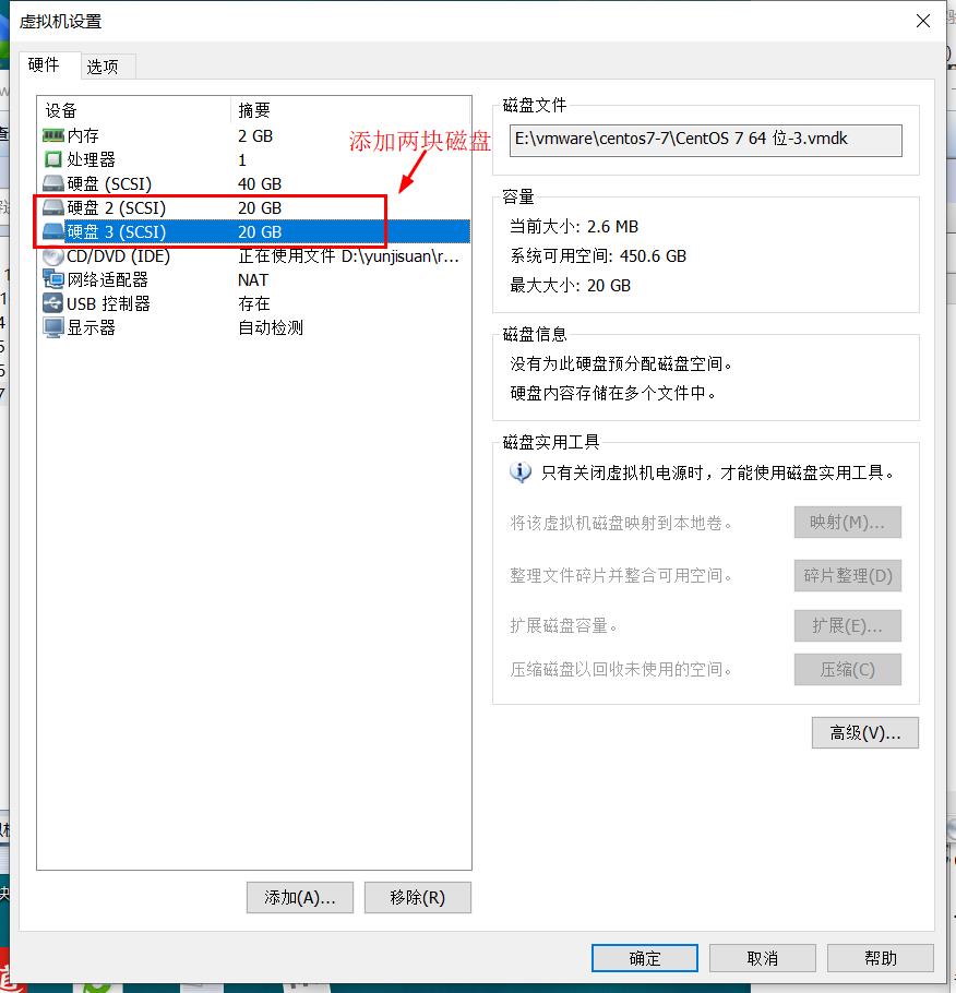
Partition:
[root@nfs ~]# fdisk /dev/sdb
 Welcome to fdisk (util Linux 2.23.2).

Changes stay in memory until you decide to write them to disk.
Think twice before using the write command.

Device does not contain a recognized partition table
 Create a new DOS disk label using disk identifier 0xf6bf2791.

Command (enter m for help): n
Partition type:
   p   primary (0 primary, 0 extended, 4 free)
   e   extended
Select (default p):
Using default response p
 Omit part of the content

[root@nfs ~]# fdisk /dev/sdc
 Welcome to fdisk (util Linux 2.23.2).

Changes stay in memory until you decide to write them to disk.
Think twice before using the write command.

Device does not contain a recognized partition table
 Use disk identifier 0xd12fa76d to create a new DOS disk label.

Command (enter m for help): n
Partition type:
Omit part of the content
Format:
[root@nfs ~]# mkfs.xfs /dev/sdb1    #Format sdb1
meta-data=/dev/sdb1              isize=512    agcount=4, agsize=1310656 blks
         =                       sectsz=512   attr=2, projid32bit=1
         =                       crc=1        finobt=0, sparse=0
data     =                       bsize=4096   blocks=5242624, imaxpct=25
         =                       sunit=0      swidth=0 blks
naming   =version 2              bsize=4096   ascii-ci=0 ftype=1
log      =internal log           bsize=4096   blocks=2560, version=2
         =                       sectsz=512   sunit=0 blks, lazy-count=1
realtime =none                   extsz=4096   blocks=0, rtextents=0
[root@nfs ~]# mkfs.xfs /dev/sdc1	#Formatting sdc
meta-data=/dev/sdc1              isize=512    agcount=4, agsize=1310656 blks
         =                       sectsz=512   attr=2, projid32bit=1
         =                       crc=1        finobt=0, sparse=0
data     =                       bsize=4096   blocks=5242624, imaxpct=25
         =                       sunit=0      swidth=0 blks
naming   =version 2              bsize=4096   ascii-ci=0 ftype=1
log      =internal log           bsize=4096   blocks=2560, version=2
         =                       sectsz=512   sunit=0 blks, lazy-count=1
realtime =none                   extsz=4096   blocks=0, rtextents=0
2.2.2 create mount point and set auto mount
[root@nfs ~]# mkdir /opt/taob /opt/jingd
[root@nfs ~]# vim /etc/fstab
#
# /etc/fstab
# Created by anaconda on Sun Dec 15 19:55:12 2019
#
# Accessible filesystems, by reference, are maintained under '/dev/disk'
# See man pages fstab(5), findfs(8), mount(8) and/or blkid(8) for more info
#
UUID=ad52e9a7-bcbd-481e-be2d-1cd6177ec542 /                       xfs     defaults        0 0
UUID=fd2b2857-4bac-494d-bdd5-45bd2ca5004d /boot                   xfs     defaults        0 0
UUID=c2f010c9-e20f-4556-a19a-ab2aa5e02ec6 /home                   xfs     defaults        0 0
UUID=f54739b0-771c-41cc-8c95-29831e2ebbf1 swap                    swap    defaults        0 0
/dev/sdb1       /opt/taob        xfs     defaults        0 0	#Mount sb1 to / opt/taob
/dev/sdc1       /opt/jingd        xfs     defaults        0 0	#Mount sdc1 to / opt/jingd
------->wq
[root@nfs ~]# mount -a			#Open mount
[root@nfs ~]# df -hT			#View mount point
//Filesystem type capacity used% free used mount point
/dev/sda2      xfs        20G  3.3G   17G   17% /
devtmpfs       devtmpfs  898M     0  898M    0% /dev
tmpfs          tmpfs     912M     0  912M    0% /dev/shm
tmpfs          tmpfs     912M  9.0M  903M    1% /run
tmpfs          tmpfs     912M     0  912M    0% /sys/fs/cgroup
/dev/sda5      xfs        10G   37M   10G    1% /home
/dev/sda1      xfs       4.0G  174M  3.9G    5% /boot
tmpfs          tmpfs     183M  4.0K  183M    1% /run/user/42
tmpfs          tmpfs     183M   20K  183M    1% /run/user/0
/dev/sr0       iso9660   4.3G  4.3G     0  100% /run/media/root/CentOS 7 x86_64
/dev/sdb1      xfs        20G   33M   20G    1% /opt/taob
/dev/sdc1      xfs        20G   33M   20G    1% /opt/jingd
2.2.3 shared storage space
[root@nfs ~]# systemctl stop firewalld.service	#Turn off firewall
[root@nfs ~]# setenforce 0		#Turn off enhanced security
[root@nfs ~]# rpm -q nfs-utils  #Check environment package
nfs-utils-1.3.0-0.48.el7.x86_64
[root@nfs ~]# rpm -q rpcbind	#Check environment package rpcbind (remote call)
rpcbind-0.2.0-42.el7.x86_64
[root@nfs ~]# vim /etc/exports	#Set up shared data
/opt/taob       192.168.100.0/24(rw,sync,no_root_squash)
/opt/jingd      192.168.100.0/24(rw,sync,no_root_squash)
#Share the mount point to the 192.168.100.0/24 network segment (enable the read-write function, enable the synchronous data write memory function, and do not demote the root user who accesses)
------->wq
[root@nfs ~]# systemctl start nfs
[root@nfs ~]# systemctl start rpcbind
#Open nfs service and rpcbind remote call service
[root@nfs ~]# showmount -e		#Query whether the storage path can be provided
Export list for nfs:
/opt/jingd 192.168.100.0/24
/opt/taob  192.168.100.0/24
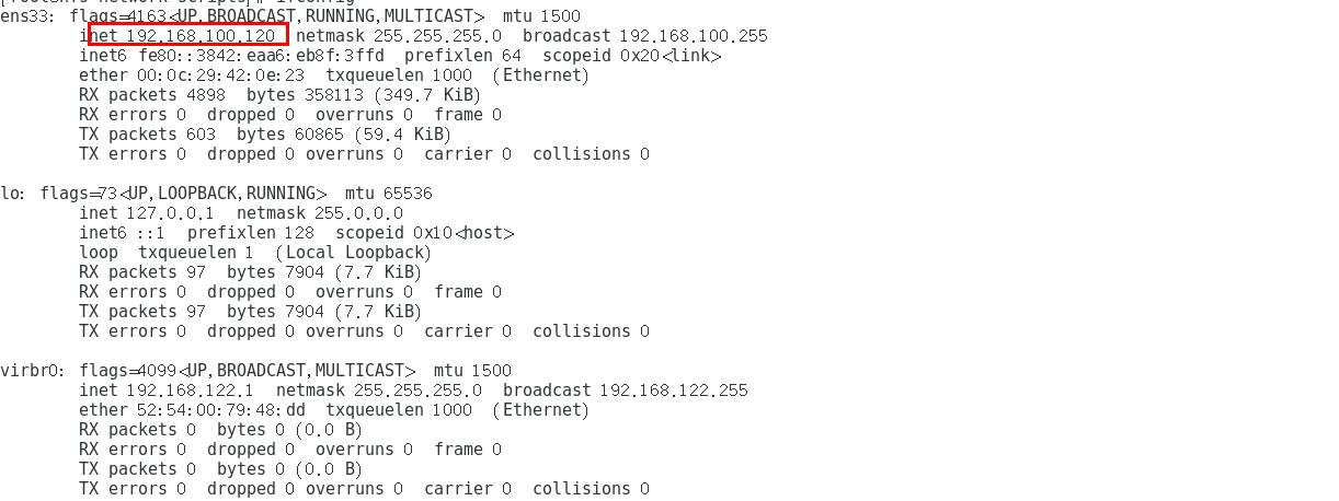
2.2.4 modify network card
[root@nfs ~]# cd /etc/sysconfig/network-scripts/
[root@nfs network-scripts]# vim ifcfg-ens33
TYPE="Ethernet"
PROXY_METHOD="none"
BROWSER_ONLY="no"
BOOTPROTO="static"		#Change dhcp dynamic get to static get static
DEFROUTE="yes"
IPV4_FAILURE_FATAL="no"
IPV6INIT="yes"
IPV6_AUTOCONF="yes"
IPV6_DEFROUTE="yes"
IPV6_FAILURE_FATAL="no"
IPV6_ADDR_GEN_MODE="stable-privacy"
NAME="ens33"
DEVICE="ens33"
ONBOOT="yes"
IPADDR=192.168.100.120			#IP address
NETMASK=255.255.255.0			#Subnet mask
GATEWAY=192.168.100.1			#gateway
------->wq
[root@nfs network-scripts]# ifconfig
-
NFS ip is:
2.3 configure web node server
2.3.1 install apache
Installing httpd on two web servers
[root@web1 ~]# yum install httpd -y
.......Omit part of the content
[root@web2 ~]# yum install httpd -y
.......Omit part of the content
2.3.2 modify two web network cards
Direct execution:
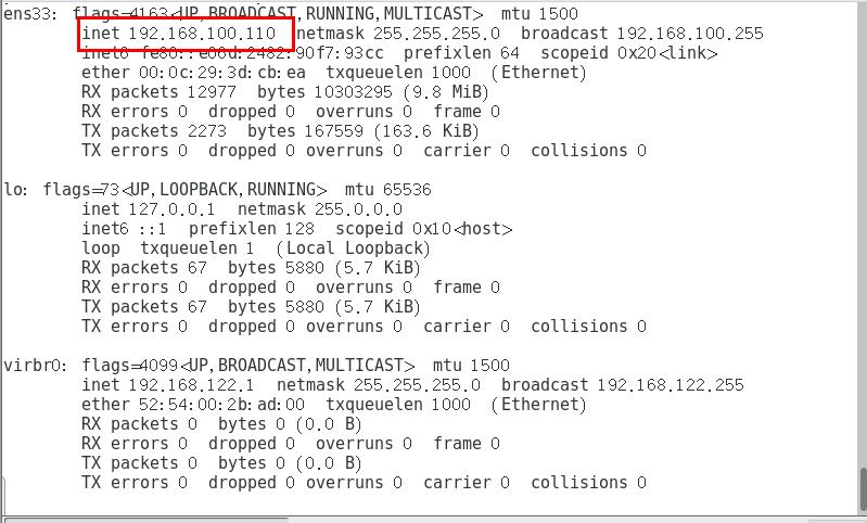
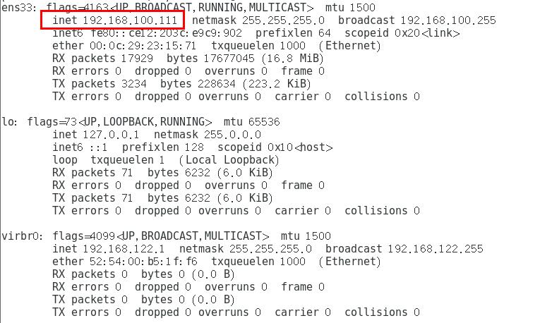
#web1
cd /etc/sysconfig/network-scripts/
sed -i '4s/dhcp/static/' ifcfg-ens33
sed -i '13d' ifcfg-ens33
cat >> /etc/sysconfig/network-scripts/ifcfg-ens33 <<-EOF
IPADDR=192.168.100.110
NETMASK=255.255.255.0
GATEWAY=192.168.100.1
EOF
#web2
cd /etc/sysconfig/network-scripts/
sed -i '4s/dhcp/static/' ifcfg-ens33
sed -i '13d' ifcfg-ens33
cat >> /etc/sysconfig/network-scripts/ifcfg-ens33 <<-EOF
IPADDR=192.168.100.111
NETMASK=255.255.255.0
GATEWAY=192.168.100.1
EOF
After the change, turn on the host only mode and restart the network card
[root@web1 ~]# systemctl stop firewalld.service
[root@web1 ~]# setenforce 0
[root@web1 ~]# systemctl restart network
-
web1 server IP is:
-
The IP address of web2 server is:
2.2.2 attaching network equipment
- Query the shared mount point on two web node servers:
#web1 node server
[root@web1 network-scripts]# showmount -e 192.168.100.120
Export list for 192.168.100.120:
/opt/jingd 192.168.100.0/24
/opt/taob  192.168.100.0/24
#web2 node server
[root@web2 network-scripts]# showmount -e 192.168.100.120
Export list for 192.168.100.120:
/opt/jingd 192.168.100.0/24
/opt/taob  192.168.100.0/24
- Mount network devices on two servers
#web1 node server
[root@web1 network-scripts]# echo '192.168.100.120:/opt/taob   /var/www/html   nfs   defaults,_netdev  0 0' >> /etc/fstab
[root@web1 network-scripts]# mount -a	#Execution takes effect
#web2 node server
[root@web2 network-scripts]# echo '192.168.100.120:/opt/jingd   /var/www/html   nfs   defaults,_netdev  0 0' >> /etc/fstab
[root@web2 network-scripts]# mount -a	#Execution takes effect
192.168.100.120:/opt/taob /var/www/html nfs defaults,_netdev 0 0 >> /etc/fstab
Meaning of attached information:
192.168.100.120:/opt/taob: indicates the address of the NFS server and its mount point
/var/www/html: the homepage of this web server
nfs: file type is nfs
defaults, _netdev: Mount similar to default and network device mount
0 0: backup, disaster recovery
- Edit the content of the site homepage in two node services
#web1 node server
[root@web1 network-scripts]# cd /var/www/html/
[root@web1 html]# vim index.html
<h1>this is taob web</h1>
------->wq
#web2 node server
[root@web2 network-scripts]# cd /var/www/html
[root@web2 html]# vim index.html
<h1>this is jingd web</h1>
------->wq
- Start the apache service and check the port status
#web1 node server
[root@web1 html]# systemctl start httpd
[root@web1 html]# netstat -natp | grep 80
tcp6       0      0 :::80                   :::*                    LISTEN      7355/httpd
#web2 node server
[root@web2 html]# systemctl start httpd
[root@web2 html]# netstat -natp | grep 80
tcp6       0      0 :::80                   :::*                    LISTEN      6732/httpd
2.4 configure LVS server
2.4.1 install ipvsadm tool, nfs
[root@localhost ~]# yum install ipvsadm -y
....Omit part of the content
root@localhost ~]# yum install nfs-utils -y
....Omit part of the content
- Open remote call service and nfs service
[root@localhost ~]# service rpcbind start
Redirecting to /bin/systemctl start rpcbind.service
[root@localhost ~]# service nfs restart
Redirecting to /bin/systemctl restart nfs.service
2.4.2 configure network card
-
In LVS server, the ens33 network card is an external network gateway and the ens36 network card is an internal network gateway. After configuration, the network card information is as follows:
-
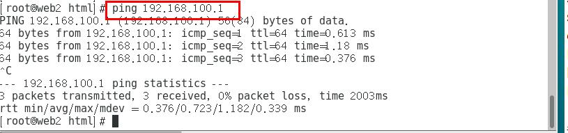
Test connectivity:
ping 192.168.100.1 with two web node servers
web1 node server: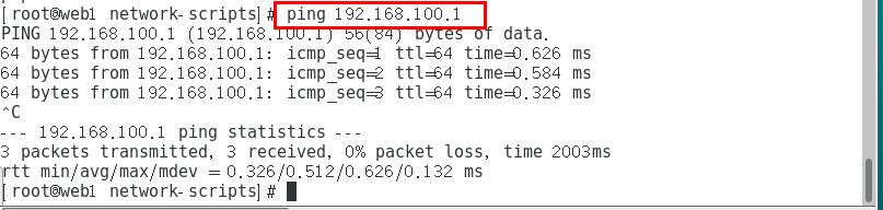
web2 node server:
2.4.3 enable route forwarding function
[root@localhost network-scripts]# cat >> /etc/sysctl.conf <<-EOF
> net.ipv4.ip_forward=1
> EOF
[root@localhost network-scripts]# sysctl -p		#Let kernel parameters take effect immediately
net.ipv4.ip_forward = 1
2.5 setting up firewall
- In the experiment, we can clear the firewall forwarding table and nat address translation table
[root@localhost network-scripts]# iptables -F
[root@localhost network-scripts]# iptables -t nat -F
- Set firewall rules (address mapping / conversion)
Method 1:
[root@localhost network-scripts]# iptables -t nat -A POSTROUTING -o ens34 -s 192.168.100.0/24 -j SNAT --to-source 12.0.0.1
Mode two:
[root@localhost network-scripts]# iptables -t nat -I POSTROUTING  -s 192.168.100.110/24 -o ens33 -j SNAT --to-source 12.0.0.1
[root@localhost network-scripts]# iptables -t nat -I POSTROUTING  -s 192.168.100.111/24 -o ens33 -j SNAT --to-source 12.0.0.1
2.6 load LVS scheduling module and define script
- Load LVS scheduling module
[root@localhost network-scripts]# modprobe ip_vs
[root@localhost network-scripts]# cat /proc/net/ip_vs
IP Virtual Server version 1.2.1 (size=4096)
Prot LocalAddress:Port Scheduler Flags
  -> RemoteAddress:Port Forward Weight ActiveConn InActConn
[root@localhost network-scripts]# ipvsadm --save > /etc/sysconfig/ipvsadm			#Save command
[root@localhost network-scripts]# systemctl start ipvsadm
#Turn on ipvsadm function
LVS scheduling module is integrated in the kernel, so we need to call
- Define script
[root@localhost network-scripts]# cd /opt
[root@localhost opt]# vim nat.sh
ipvsadm -C
ipvsadm -A -t 12.0.0.1:80 -s rr
ipvsadm -a -t 12.0.0.1:80 -r 192.168.100.110:80 -m
ipvsadm -a -t 12.0.0.1:80 -r 192.168.100.111:80 -m
ipvsadm
------>wq
[root@localhost opt]# chmod +x nat.sh
[root@localhost opt]# ./nat.sh
IP Virtual Server version 1.2.1 (size=4096)
Prot LocalAddress:Port Scheduler Flags
  -> RemoteAddress:Port           Forward Weight ActiveConn InActConn
TCP  localhost.localdomain:http rr
  -> 192.168.100.110:http         Masq    1      0          0
  -> 192.168.100.111:http         Masq    1      0          0
Among them:
ipvsadm -C: clear ipvs cache, equivalent to initialization
ipvsadm -A -t 12.0.0.1:80 -s rr: Specifies that an access port ip port is 80 specifies the scheduling algorithm rr (polling)
ipvsadm -a -t 12.0.0.1:80 -r 192.168.100.110:80 -m:
-a is for adding real server to establish ip address mapping relationship. The mapping address is 12.0.0.1
-r = add real IP address is 192.168.100.110
-m specifies that the polling mechanism enabled uses the LVS mode of NAT
2.7 verification results
Change the IPV4 settings as follows: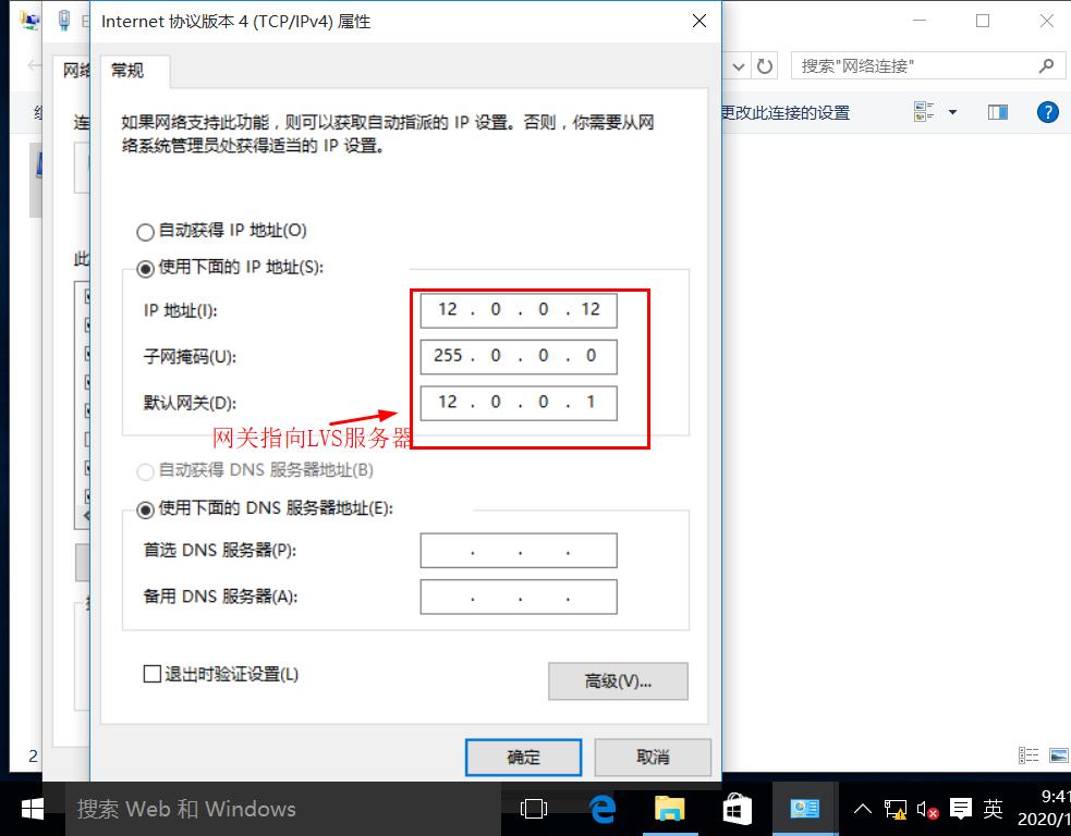
Use the browser to visit 12.0.0.1 to view the display page:
Refresh page view page: Experiments show that LVS responds to customer requests by polling, and LVS load balancing NAT mode experiment is successful
Conclusion:
This blog mainly introduces the theory of load balancing cluster and the experiment of LVS nat mode, and then it will continue to introduce the configuration steps of DR mode. In the NAT experiment, the client cannot access the intranet web server: 1. The firewall rules are set incorrectly; 2. The firewall in the intranet is not closed, and so on. If the virtual machine is restarted in the experiment, the firewall and enhanced security can be checked first Check whether the full function is off, and then check whether the nfs server uses "df -hT" to check the mount status. Restarting the virtual machine may cause the mount fails to take effect or mount.

