Chapter 0: Preface
- The smart car design starts from 0 and involves multiple modules
- This article includes not only the production process, but also some problems and solutions encountered in the production process.
- If the clock is not set, the system default clock is 72MHz, which is in the system_stm32f10x.c file (#define SYSCLK_FREQ_72MHz 72000000)
Chapter 1: let the car move
Knowledge points and modules involved
- Modules involved: two-way BTN drive module, LM317 adjustable voltage stabilizing module
- PWM speed regulation: energizing the positive and negative poles of the motor can directly make the motor rotate, but PWM is needed to control the rotation speed of the motor. When the power on duty cycle is set to be smaller (the ratio of power on time to one cycle), the phenomenon of the motor is the reduction of speed.
- Forward and reverse: connect the two wires on the motor in reverse.
- Prescaler = main frequency ÷ clock frequency - 1 (frequency after frequency division); 72000000÷10000=7200-1
- Counting cycle Period = clock frequency ÷ target frequency - 1
- PWM initialization procedure is as follows: Channel 3 of TIM2 is used here as PWM output (PA2 connected to A1 and PA3 connected to A2)
- A1/A2/B1/B2 refers to the interface on the drive module.
Experimental code
void pwm_init_left(void)
{
    GPIO_InitTypeDef GPIO_InitStructure;   //Declare a structure variable to initialize GPIO

    TIM_TimeBaseInitTypeDef TIM_TimeBaseInitStructure;//Declare a structure variable to initialize the timer

    TIM_OCInitTypeDef TIM_OCInitStructure;//According to Tim_ Initialize peripheral TIMx with the parameters specified in ocinitstruct

    /* Turn on the clock */
    RCC_APB2PeriphClockCmd(RCC_APB2Periph_GPIOA | RCC_APB2Periph_AFIO, ENABLE);
    RCC_APB1PeriphClockCmd(RCC_APB1Periph_TIM2,ENABLE);

    /*  Configure GPIO mode and IO port PA2*/
    GPIO_InitStructure.GPIO_Pin=GPIO_Pin_2|GPIO_Pin_3;
    GPIO_InitStructure.GPIO_Speed=GPIO_Speed_50MHz;
    GPIO_InitStructure.GPIO_Mode=GPIO_Mode_AF_PP;//Multiplex push-pull output
    GPIO_Init(GPIOA,&GPIO_InitStructure);


    // T = CNT/fHz = 9000/72000000s
    // Period = clock frequency ÷ target frequency - 1
    // Prescaler = dominant frequency ÷ target frequency - 1 (frequency after frequency division); 72000000÷10000=7200-1
    //TIM2 timer initialization
    TIM_TimeBaseInitStructure.TIM_Period = 99;       //Cycle, no frequency division, set the value of automatic reload register cycle
    TIM_TimeBaseInitStructure.TIM_Prescaler = 719;//Set the prescaled value used as TIMx clock frequency (main frequency ÷ target frequency - 1).
    TIM_TimeBaseInitStructure.TIM_ClockDivision = 0;//Set clock split:
    TIM_TimeBaseInitStructure.TIM_CounterMode = TIM_CounterMode_Up;    //TIM up count mode
    TIM_TimeBaseInit(TIM2, & TIM_TimeBaseInitStructure);

    // fll remap the output pin of TIM2 to PA15, that is, P3 seven
    //GPIO_PinRemapConfig(GPIO_FullRemap_TIM2, ENABLE);


    //PWM initialization / / according to Tim_ Initialize peripheral TIMx with the parameters specified in ocinitstruct
    TIM_OCInitStructure.TIM_OCMode=TIM_OCMode_PWM1;
    TIM_OCInitStructure.TIM_OutputState=TIM_OutputState_Enable;//PWM output enable
    TIM_OCInitStructure.TIM_Pulse = 50;
    TIM_OCInitStructure.TIM_OCPolarity = TIM_OCPolarity_High;

    TIM_OC3Init(TIM2,&TIM_OCInitStructure);

    TIM_OC3PreloadConfig(TIM2, TIM_OCPreload_Enable);
    TIM_ARRPreloadConfig(TIM2,ENABLE);

    TIM_Cmd(TIM2,ENABLE);//Enable TIMx peripherals
}
Problems encountered
- First use of J_Link requires J_Link driver, which directly downloads the < driver wizard > software. It will automatically detect the missing driver and download and install it.
- Using J_ When debugging link, you should download the program first and then use J_link. My is that this happens, others don't know. (at the beginning of the commissioning procedure, the motor can rotate but can not adjust the speed, which is because of this situation)
- TIM_ OCInitStructure. TIM_ The value of pulse cannot be set too small, otherwise the motor will not rotate, and it will not rotate when it is set to 40 (another problem here is that when the value is set to exceed 50, the motor speed is almost the same, that is, the speed cannot be changed)
- Another problem is that this method cannot change the forward and reverse rotation of the motor, because only one channel is used here.
Problem solution
- First tim_ The value of pulse cannot be set too small: it is detected to be Tim_ The value of period cycle is set too small, the frequency is too high, and the motor does not have such good performance. Tim can be_ The period period is set to 7200-1 and the frequency is 10khz.
- Then there is the problem of forward and reverse rotation of the motor: four different channels (OC1/2/3/4) of the same timer can be connected to A1/A2/B1/B2 respectively, and then the values of the comparison registers of the four channels can be set to realize forward and reverse rotation (for example, setting the comparison value of OC1 to 5000 and the comparison value of OC2 to 0 can realize forward rotation; otherwise, it can be reversed)
- If it is written as above, the four channels need to write a lot of code, so a little change has been made here.
- The value in the comparison register set here is applied to Tim in the library function_ SetCompare_ X function.
/**
  * @brief  Sets the TIMx Capture Compare1 Register value
  * @param  TIMx: where x can be 1 to 17 except 6 and 7 to select the TIM peripheral.
  * @param  Compare1: specifies the Capture Compare1 register new value.
  * @retval None
  */
void TIM_SetCompare1(TIM_TypeDef* TIMx, uint16_t Compare1)
{
  /* Check the parameters */
  assert_param(IS_TIM_LIST8_PERIPH(TIMx));
  /* Set the Capture Compare1 Register value */
  TIMx->CCR1 = Compare1;
}
Solution code
//PA0-4 for PWM output
void PWM_TIM_2_Init(u16 Period,u16 Prescaler)
{
    GPIO_InitTypeDef GPIO_InitStructure;   //Declare a structure variable to initialize GPIO

    TIM_TimeBaseInitTypeDef TIM_TimeBaseInitStructure;//Declare a structure variable to initialize the timer

    TIM_OCInitTypeDef TIM_OCInitStructure;//According to Tim_ Initialize peripheral TIMx with the parameters specified in ocinitstruct

    /* Turn on the clock */
    RCC_APB2PeriphClockCmd(RCC_APB2Periph_GPIOA | RCC_APB2Periph_AFIO, ENABLE);
    RCC_APB1PeriphClockCmd(RCC_APB1Periph_TIM2,ENABLE);

    /*  Configure GPIO mode and IO port PA0 1 2 3*/
    GPIO_InitStructure.GPIO_Pin=GPIO_Pin_0|GPIO_Pin_1|GPIO_Pin_2|GPIO_Pin_3;
    GPIO_InitStructure.GPIO_Speed=GPIO_Speed_50MHz;
    GPIO_InitStructure.GPIO_Mode=GPIO_Mode_AF_PP;//Multiplex push-pull output
    GPIO_Init(GPIOA,&GPIO_InitStructure);

    // T = CNT/fHz = 9000/72000000s
    // Period = clock frequency ÷ target frequency - 1
    // Prescaler = dominant frequency ÷ clock frequency - 1 (frequency after frequency division); 72000000÷10000=720-1
    //TIM3 timer initialization
    TIM_TimeBaseInitStructure.TIM_Period = Period;       //Cycle, no frequency division, set the value of automatic reload register cycle
    TIM_TimeBaseInitStructure.TIM_Prescaler = Prescaler;//Set the prescaled value used as TIMx clock frequency (main frequency ÷ target frequency - 1)
    TIM_TimeBaseInitStructure.TIM_ClockDivision = TIM_CKD_DIV1;//Set clock split:
    TIM_TimeBaseInitStructure.TIM_CounterMode = TIM_CounterMode_Up;    //TIM up count mode
    TIM_TimeBaseInit(TIM2, & TIM_TimeBaseInitStructure);

    // fll remap the output pin of TIM2 to PA15, that is, P3 seven
    //GPIO_PinRemapConfig(GPIO_FullRemap_TIM2, ENABLE);


    //PWM initialization / / according to Tim_ Initialize peripheral TIMx with the parameters specified in ocinitstruct
    TIM_OCInitStructure.TIM_OCMode=TIM_OCMode_PWM1;
    TIM_OCInitStructure.TIM_OutputState=TIM_OutputState_Enable;//PWM output enable
    TIM_OCInitStructure.TIM_Pulse = 0;
    TIM_OCInitStructure.TIM_OCPolarity = TIM_OCPolarity_High;

    TIM_OC1Init(TIM2,&TIM_OCInitStructure);
    TIM_OC2Init(TIM2,&TIM_OCInitStructure);
    TIM_OC3Init(TIM2,&TIM_OCInitStructure);
    TIM_OC4Init(TIM2,&TIM_OCInitStructure);

    TIM_OC1PreloadConfig(TIM2, TIM_OCPreload_Enable);
    TIM_OC2PreloadConfig(TIM2, TIM_OCPreload_Enable);
    TIM_OC3PreloadConfig(TIM2, TIM_OCPreload_Enable);
    TIM_OC4PreloadConfig(TIM2, TIM_OCPreload_Enable);

    TIM_ARRPreloadConfig(TIM2,ENABLE);    //TIM2 preloads register enable on ARR
    TIM_Cmd(TIM2,ENABLE);                                //Enable TIMx peripherals
}


int main(void)
{

    PWM_TIM_2_Init(7199,0);

    //Forward rotation
    TIM_SetCompare1(TIM2,5000);
    TIM_SetCompare2(TIM2,0);
    //reversal
    TIM_SetCompare3(TIM2,0);
    TIM_SetCompare4(TIM2,3000);

    while(1)
    {

    }
}
Chapter II: measuring trolley speed (encoder)
Photoelectric encoder
Motor wiring diagram: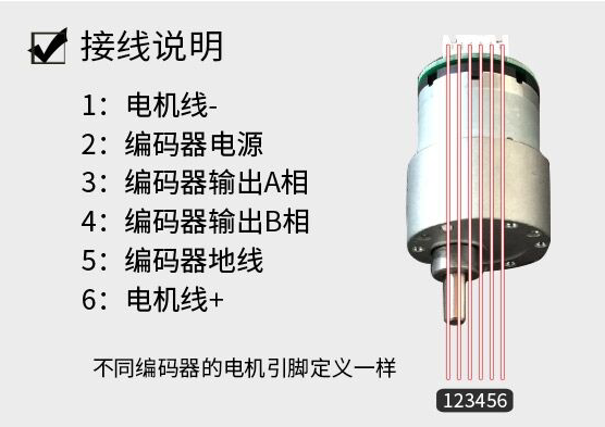
- The photoelectric encoder outputs sine wave, and both phase A and phase B output sine wave.
- When phase A is the rising edge, if phase B is low level, the motor rotates forward.
- When phase A is the rising edge, if phase B is high level, the motor will reverse.
- Note: since I only capture the rising edge of phase A here, the line of phase AB cannot be reversed, otherwise the interrupt of channel 1 of TIM3 cannot be triggered.
Input capture
- Function: used to measure the pulse width of the input signal, the frequency and duty cycle of the PWM input signal.
Implementation process:
- First, configure a timer to the counter mode (the frequency of the counter must be much greater than the input frequency)
- Then configure a channel of the timer as the capture channel (configured as rising edge detection or falling edge detection)
- When the channel detects the corresponding edge, it will trigger the interrupt of the channel (at this time, the value of the counter will be automatically loaded into the capture comparison register)
- The period of the input waveform = the difference between the values of two adjacent capture registers * the period value of the counter.
Experimental code
u8 i = 0;                                 //Flag first or second detected rising edge
u16 BianMaQi_speed_ZUO = 0;  //The count value of the timer when the output of the encoder is 1 cycle
u16 BianMaQi_speed_YOU = 0;
u8 zhen_fan_zhuan_ZUO = 0;   //Mark whether the motor rotates forward or reverse (1 positive and 0 negative)
u8 zhen_fan_zhuan_YOU = 0;
u16    zhuan_su_ZUO = 0;                 //Trolley Speed r/min
u16    zhuan_su_YOU = 0;
double BianMaQi_ZUO_zhouqi = 0.0;//Encoder cycle
double BianMaQi_YOU_zhouqi = 0.0;

/*******************************************************************************
* Function name: TIM3_CH1_Input_Init (using TIM3, channel 1 PA6 is connected to left wheel phase A and channel 2 PA7 is connected to left wheel phase B)
*    Function parameter: arr: automatic reload value; psc: prescaled coefficient
*    Function return value: None
* Function: TIM3_CH1 input capture initialization function (only capture the waveform of channel 1)
*******************************************************************************/
void TIM3_CH1_Input_Init(u16 Period,u16 Prescaler)
{
    TIM_TimeBaseInitTypeDef TIM_TimeBaseInitStructure;
    TIM_ICInitTypeDef TIM_ICInitStructure;
    NVIC_InitTypeDef NVIC_InitStructure;
    GPIO_InitTypeDef GPIO_InitStructure;

    RCC_APB2PeriphClockCmd(RCC_APB2Periph_GPIOA,ENABLE);
    RCC_APB1PeriphClockCmd(RCC_APB1Periph_TIM3,ENABLE);//Enable TIM3 clock

    GPIO_InitStructure.GPIO_Pin=GPIO_Pin_6|GPIO_Pin_7;//Pin setting
    GPIO_InitStructure.GPIO_Mode=GPIO_Mode_IPU;     //Set the pull-up input mode
    GPIO_Init(GPIOA,&GPIO_InitStructure);        /* Initialize GPIO */

    TIM_TimeBaseInitStructure.TIM_Period=Period;   //Auto load value
    TIM_TimeBaseInitStructure.TIM_Prescaler=Prescaler; //division factor
    TIM_TimeBaseInitStructure.TIM_ClockDivision=TIM_CKD_DIV1;
    TIM_TimeBaseInitStructure.TIM_CounterMode=TIM_CounterMode_Up; //Set up count mode
    TIM_TimeBaseInit(TIM3,&TIM_TimeBaseInitStructure);

    TIM_ICInitStructure.TIM_Channel=TIM_Channel_1; //Channel 1
    TIM_ICInitStructure.TIM_ICFilter=0x00;  //No filtering
    TIM_ICInitStructure.TIM_ICPolarity=TIM_ICPolarity_Rising;//Capture polarity
    TIM_ICInitStructure.TIM_ICPrescaler=TIM_ICPSC_DIV1; //division factor
    TIM_ICInitStructure.TIM_ICSelection=TIM_ICSelection_DirectTI;//Map directly to TI1
    TIM_ICInit(TIM3,&TIM_ICInitStructure);
    TIM_ITConfig(TIM3,TIM_IT_Update,ENABLE);
    TIM_ITConfig(TIM3,TIM_IT_CC1,ENABLE);

    NVIC_InitStructure.NVIC_IRQChannel = TIM3_IRQn;//Interrupt channel
    NVIC_InitStructure.NVIC_IRQChannelPreemptionPriority=2;//Preemption Priority
    NVIC_InitStructure.NVIC_IRQChannelSubPriority =0;        //Sub priority
    NVIC_InitStructure.NVIC_IRQChannelCmd = ENABLE;            //IRQ channel enable
    NVIC_Init(&NVIC_InitStructure);

    TIM_Cmd(TIM3,ENABLE); //Enable timer
}


/*******************************************************************************
* Function name: TIM3_IRQHandler
*    Function parameters: None
*    Function return value: None
* Function function: TIM3 interrupt function (read the value of TIM3 counter and detect whether the motor rotates forward or reverse)
*******************************************************************************/
void TIM3_IRQHandler(void)
{

    if(TIM_GetITStatus(TIM3,TIM_IT_CC1) == 1)          //Detect whether channel 1 of TIM3 is interrupted
    {
        if(TIM_GetFlagStatus(TIM3,TIM_FLAG_CC1))
        {

            BianMaQi_speed_ZUO = TIM_GetCounter(TIM3) - BianMaQi_speed_ZUO;
            BianMaQi_ZUO_zhouqi = BianMaQi_speed_ZUO * 1/1000000;                //Calculate the period of the encoder
            zhuan_su_ZUO = BianMaQi_ZUO_zhouqi * 500;                                        //Trolley Speed r/min
            i++;

        }
        if(GPIO_ReadInputDataBit(GPIOA,GPIO_Pin_7) == 0)        //Phase A is the rising edge, phase B is 0, positive rotation
        {

            zhen_fan_zhuan_ZUO = 1;
        }
        else
        {
            zhen_fan_zhuan_ZUO = 0;
        }
        if(i==2)
        {
            TIM_SetCounter(TIM3,0);     //The counter of timer 3 is cleared
            TIM_Cmd(TIM3,ENABLE);            //Enable timer 3
            BianMaQi_speed_ZUO = 0;
            i = 0;
        }

        TIM_ClearITPendingBit(TIM3,TIM_IT_CC1|TIM_IT_Update);        //Clear the interrupt hold bit of TIMx
    }

}


/*******************************************************************************
* Function name: TIM4_CH3_Input_Init (channel 3 PB8 of TIM4 is connected to phase A of right wheel and channel 2 PB9 is connected to phase B of right wheel)
* Function parameter: arr: automatic reload value; psc: prescaled coefficient
* Function return value: None
* Function: TIM4_CH3 input capture initialization function (only capture the waveform of channel 3)
*******************************************************************************/
void TIM4_CH3_Input_Init(u16 Period,u16 Prescaler)
{
    TIM_TimeBaseInitTypeDef TIM_TimeBaseInitStructure;
    TIM_ICInitTypeDef TIM_ICInitStructure;
    NVIC_InitTypeDef NVIC_InitStructure;
    GPIO_InitTypeDef GPIO_InitStructure;

    RCC_APB2PeriphClockCmd(RCC_APB2Periph_GPIOB,ENABLE);
    RCC_APB1PeriphClockCmd(RCC_APB1Periph_TIM4,ENABLE);//Enable TIM4 clock

    GPIO_InitStructure.GPIO_Pin=GPIO_Pin_8|GPIO_Pin_9;//Pin setting
    GPIO_InitStructure.GPIO_Mode=GPIO_Mode_IPU;     //Set the pull-up input mode
    GPIO_Init(GPIOB,&GPIO_InitStructure);        /* Initialize GPIO */

    TIM_TimeBaseInitStructure.TIM_Period=Period;   //Auto load value
    TIM_TimeBaseInitStructure.TIM_Prescaler=Prescaler; //division factor
    TIM_TimeBaseInitStructure.TIM_ClockDivision=TIM_CKD_DIV1;
    TIM_TimeBaseInitStructure.TIM_CounterMode=TIM_CounterMode_Up; //Set up count mode
    TIM_TimeBaseInit(TIM4,&TIM_TimeBaseInitStructure);

    TIM_ICInitStructure.TIM_Channel=TIM_Channel_3; //Channel 1
    TIM_ICInitStructure.TIM_ICFilter=0x00;  //No filtering
    TIM_ICInitStructure.TIM_ICPolarity=TIM_ICPolarity_Rising;//Capture polarity
    TIM_ICInitStructure.TIM_ICPrescaler=TIM_ICPSC_DIV1; //division factor
    TIM_ICInitStructure.TIM_ICSelection=TIM_ICSelection_DirectTI;//Map directly to TI1
    TIM_ICInit(TIM4,&TIM_ICInitStructure);
    TIM_ITConfig(TIM4,TIM_IT_Update,ENABLE);
    TIM_ITConfig(TIM4,TIM_IT_CC3,ENABLE);

    NVIC_InitStructure.NVIC_IRQChannel = TIM4_IRQn;//Interrupt channel
    NVIC_InitStructure.NVIC_IRQChannelPreemptionPriority=2;//Preemption Priority
    NVIC_InitStructure.NVIC_IRQChannelSubPriority =0;        //Sub priority
    NVIC_InitStructure.NVIC_IRQChannelCmd = ENABLE;            //IRQ channel enable
    NVIC_Init(&NVIC_InitStructure);

    TIM_Cmd(TIM4,ENABLE); //Enable timer
}


/*******************************************************************************
* Function name: TIM4_IRQHandler
* Function parameters: None
* Function return value: None
* Function function: TIM4 interrupt function (read the value of TIM4 counter and detect whether the motor rotates forward or reverse)
*******************************************************************************/
void TIM4_IRQHandler(void)
{

    if(TIM_GetITStatus(TIM4,TIM_IT_CC3) == 1)          //Detect whether channel 1 of TIM3 is interrupted
    {
        if(TIM_GetFlagStatus(TIM4,TIM_FLAG_CC3))
        {

            BianMaQi_speed_YOU = TIM_GetCounter(TIM4) - BianMaQi_speed_YOU;
            BianMaQi_YOU_zhouqi = BianMaQi_speed_YOU * 1/1000000;                //Calculate the period of the encoder
            zhuan_su_YOU = BianMaQi_YOU_zhouqi * 500;                                        //Trolley Speed r/min
            i++;

        }
        if(GPIO_ReadInputDataBit(GPIOB,GPIO_Pin_9) == 0)        //Phase A is the rising edge, phase B is 0, positive rotation
        {

            zhen_fan_zhuan_YOU = 1;
        }
        else
        {
            zhen_fan_zhuan_YOU = 0;
        }
        if(i==2)
        {
            TIM_SetCounter(TIM4,0);     //The counter of timer 3 is cleared
            TIM_Cmd(TIM4,ENABLE);            //Enable timer 3
            BianMaQi_speed_YOU = 0;
            i = 0;
        }

        TIM_ClearITPendingBit(TIM4,TIM_IT_CC3|TIM_IT_Update);        //Clear the interrupt hold bit of TIMx
    }

}
Problems encountered
After two input capture initialization functions (TIM3_CH1_Input_Init and TIM4_CH3_Input_Init) are referenced in the mian function, the set comparison register function Tim is referenced_ When setcompare1, the motor does not rotate. After testing, there is a problem with the input capture initialization function (when TIM_SetCompare1 is used before this function, the motor can rotate)
- Code example
int main(void)
{
  NVIC_PriorityGroupConfig(NVIC_PriorityGroup_2);  //Interrupt priority grouping is divided into 2 groups

  PWM_TIM_2_Init(7199,0);

  TIM3_CH1_Input_Init(0xffff,0);
  TIM4_CH3_Input_Init(0xffff,0);

  TIM_SetCompare1(TIM2,0);
  TIM_SetCompare2(TIM2,5000);
  TIM_SetCompare3(TIM2,0);
  TIM_SetCompare4(TIM2,5000);
  while(1)
  {

  }
}
Solution
- Set tim3_ CH1_ Input_ The interrupt nested NVIC setting in init function can be turned off.
/*******************************************************************************
* Function name: TIM3_CH1_Input_Init (using TIM3, channel 1 PA6 is connected to left wheel phase A and channel 2 PA7 is connected to left wheel phase B)
*    Function parameter: arr: automatic reload value; psc: prescaled coefficient
*    Function return value: None
* Function: TIM3_CH1 input capture initialization function (only capture the waveform of channel 1)
*******************************************************************************/
void TIM3_CH1_Input_Init(u16 Period,u16 Prescaler)
{
    TIM_TimeBaseInitTypeDef TIM_TimeBaseInitStructure;
    TIM_ICInitTypeDef TIM_ICInitStructure;
    //NVIC_InitTypeDef NVIC_InitStructure;
    GPIO_InitTypeDef GPIO_InitStructure;

    RCC_APB2PeriphClockCmd(RCC_APB2Periph_GPIOA,ENABLE);
    RCC_APB1PeriphClockCmd(RCC_APB1Periph_TIM3,ENABLE);//Enable TIM3 clock

    GPIO_InitStructure.GPIO_Pin=GPIO_Pin_6|GPIO_Pin_7;//Pin setting
    GPIO_InitStructure.GPIO_Mode=GPIO_Mode_IN_FLOATING;     //Set the pull-up input mode
    GPIO_Init(GPIOA,&GPIO_InitStructure);        /* Initialize GPIO */

    TIM_TimeBaseInitStructure.TIM_Period=Period;   //Auto load value
    TIM_TimeBaseInitStructure.TIM_Prescaler=Prescaler; //division factor
    TIM_TimeBaseInitStructure.TIM_ClockDivision=TIM_CKD_DIV1;
    TIM_TimeBaseInitStructure.TIM_CounterMode=TIM_CounterMode_Up; //Set up count mode
    TIM_TimeBaseInit(TIM3,&TIM_TimeBaseInitStructure);

    TIM_ICInitStructure.TIM_Channel=TIM_Channel_1; //Channel 1
    TIM_ICInitStructure.TIM_ICFilter=0x00;  //No filtering
    TIM_ICInitStructure.TIM_ICPolarity=TIM_ICPolarity_Rising;//Capture polarity
    TIM_ICInitStructure.TIM_ICPrescaler=TIM_ICPSC_DIV1; //division factor
    TIM_ICInitStructure.TIM_ICSelection=TIM_ICSelection_DirectTI;//Map directly to TI1
    TIM_ICInit(TIM3,&TIM_ICInitStructure);
    TIM_ITConfig(TIM3,TIM_IT_Update,ENABLE);
    TIM_ITConfig(TIM3,TIM_IT_CC1,ENABLE);

    //NVIC_InitStructure.NVIC_IRQChannel = TIM3_IRQn;// Interrupt channel
    //NVIC_InitStructure.NVIC_IRQChannelPreemptionPriority=2;// Preemption Priority
    //NVIC_InitStructure.NVIC_IRQChannelSubPriority =0;        // Sub priority
    //NVIC_InitStructure.NVIC_IRQChannelCmd = ENABLE;            //IRQ channel enable
    //NVIC_Init(&NVIC_InitStructure);

    TIM_Cmd(TIM3,ENABLE); //Enable timer
}
Chapter 3: the addition of Bluetooth module
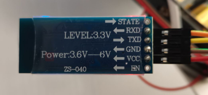
- Configure USART serial port and use usart1 of MCU_ TX connection RXD, USART1_RX is connected to TXD.
- Note: the baud rate of Bluetooth must be the same as that of serial port.
- See another article about serial port: https://segmentfault.com/a/11...
Problems encountered and Solutions
- Problem: after configuring the serial port, the mobile phone connects to Bluetooth, resulting in garbled code (this should be a common problem of the serial port)
- Problem: baud rate mismatch.
- Solution: after detection, the default baud rate of Bluetooth module is 9600. Although I have set the baud rate of serial port to 9600, there is still garbled code. The reason is that the library uses 8MHz crystal oscillator by default, and 25MHz or 12M crystal oscillator can be used through macro; Specifically defined in stm32f10x H in the document, HSE_VALUE is defined as 8000000 at the beginning and changed to 12000000. After that, the serial communication can be displayed normally.
Code example
#include "usart.h"


unsigned char Data;

/*******************************************************************************
* Function name: USART1_Init
* Function: USART1 initialization function
* Input: bound: baud rate
* Output: None
*******************************************************************************/
void USART1_Init(u32 bound)
{
   //GPIO port settings
    GPIO_InitTypeDef GPIO_InitStructure;
    USART_InitTypeDef USART_InitStructure;
    NVIC_InitTypeDef NVIC_InitStructure;

    RCC_APB2PeriphClockCmd(RCC_APB2Periph_GPIOA,ENABLE);
    RCC_APB2PeriphClockCmd(RCC_APB2Periph_USART1,ENABLE);
    RCC_APB2PeriphClockCmd(RCC_APB2Periph_AFIO,ENABLE);     //Turn on the clock


    /*  Configure GPIO mode and IO port */
    GPIO_InitStructure.GPIO_Pin=GPIO_Pin_9;//TX / / serial port output PA9
    GPIO_InitStructure.GPIO_Speed=GPIO_Speed_50MHz;
    GPIO_InitStructure.GPIO_Mode=GPIO_Mode_AF_PP;        //Multiplex push-pull output
    GPIO_Init(GPIOA,&GPIO_InitStructure);  /* Initialize serial port input IO */

    GPIO_InitStructure.GPIO_Pin=GPIO_Pin_10;//RX / / serial port input PA10
    GPIO_InitStructure.GPIO_Mode=GPIO_Mode_IN_FLOATING;          //Analog input
    GPIO_Init(GPIOA,&GPIO_InitStructure); /* Initialize GPIO */

    //Usart1 NVIC configuration
    NVIC_InitStructure.NVIC_IRQChannel = USART1_IRQn;//Serial port 1 interrupt channel
    NVIC_InitStructure.NVIC_IRQChannelPreemptionPriority=3;//Preemption priority 3
    NVIC_InitStructure.NVIC_IRQChannelSubPriority =3;        //Sub priority 3
    NVIC_InitStructure.NVIC_IRQChannelCmd = ENABLE;            //IRQ channel enable
    NVIC_Init(&NVIC_InitStructure);    //Initializes the VIC register according to the specified parameters


   //USART1 initialization settings
    USART_InitStructure.USART_BaudRate = bound;//Baud rate setting
    USART_InitStructure.USART_WordLength = USART_WordLength_8b;//The word length is in 8-bit data format
    USART_InitStructure.USART_StopBits = USART_StopBits_1;//A stop bit
    USART_InitStructure.USART_Parity = USART_Parity_No;//No parity bit
    USART_InitStructure.USART_HardwareFlowControl = USART_HardwareFlowControl_None;//No hardware data flow control
    USART_InitStructure.USART_Mode = USART_Mode_Rx | USART_Mode_Tx;    //Transceiver mode
    USART_Init(USART1, &USART_InitStructure); //Initialize serial port 1

    USART_Cmd(USART1, ENABLE);  //Enable serial port 1

    USART_ClearFlag(USART1, USART_FLAG_TC);

    USART_ITConfig(USART1, USART_IT_RXNE, ENABLE);//Turn on related interrupt


}

/*******************************************************************************
* Function name: USART1_IRQHandler
* Function: USART1 interrupt function
* Input: None
* Output: None
*******************************************************************************/
void USART1_IRQHandler(void)                    //Serial port 1 interrupt service program
{

    if(USART_GetITStatus(USART1, USART_IT_RXNE) != RESET)  //Receive interrupt
    {
        Data = USART_ReceiveData(USART1);//(USART1->DR);    // Read received data
    USART_SendData(USART1,Data);
        while(USART_GetFlagStatus(USART1,USART_FLAG_TC) != SET);
    }
    USART_ClearFlag(USART1,USART_FLAG_TC);
    USART_ClearITPendingBit(USART1,USART_IT_RXNE);
}