catalogue
2.2 function description of each module
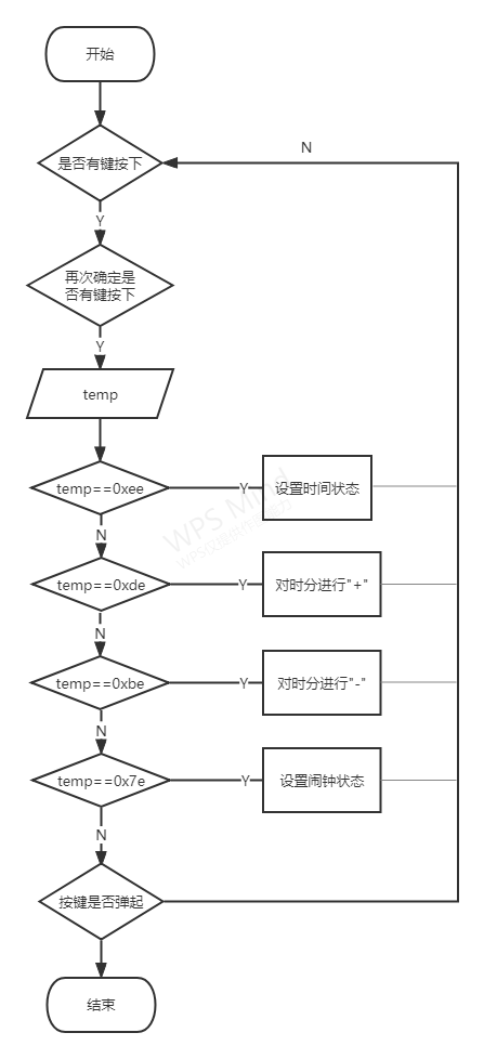
4.1 overall procedure flow chart
1, Design content
Content: the design of basic digital electronic clock is realized by single chip microcomputer control. 4X4 keyboard and 4-bit LED digital display are expanded, which can be used for display and key control.
Function: can display hours and minutes; The alarm clock function can be set by pressing the key; The whole time can be reported; It can be set by pressing the key.
2, Overall scheme design
2.1 functional analysis
Digital electronic clock system can be divided into main control unit, reset circuit, keyboard circuit, display circuit, etc.
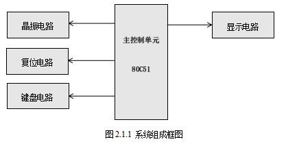
2.2 function description of each module
Function of crystal oscillator circuit: there is a crystal oscillator in each single chip microcomputer system. The whole process is called crystal oscillator. In the single chip microcomputer system, the crystal oscillator plays a very important role. It combines the internal circuit of the single chip microcomputer to generate the necessary clock frequency of the single chip microcomputer. The execution of all instructions of the single chip microcomputer is based on this foundation. The higher the clock frequency provided by the crystal oscillator, The faster the MCU runs. Crystal oscillator uses a crystal that can convert electrical energy and mechanical energy into each other to work in a resonant state to provide stable and accurate single frequency oscillation.
Function of reset circuit: initialize the circuit to a certain state. Generally speaking, the function of MCU reset circuit is to initialize a state machine to an empty state. In the MCU, when resetting, the MCU loads some registers and storage devices into a value preset by the manufacturer.
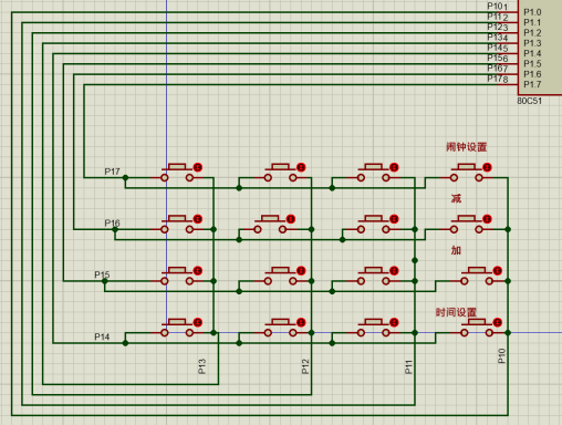
Keyboard circuit: according to 4 × 4 matrix keyboard, which is a keyboard composed of four I/O lines as row lines and four I/O lines as column lines. Set a key at each intersection of row and column lines. In this way, the number of keys on the keyboard is 4 × Four. This determinant keyboard structure can effectively improve the utilization of I/O port in single chip microcomputer system. Realize the function of pressing the key to control the alarm clock and set the time.
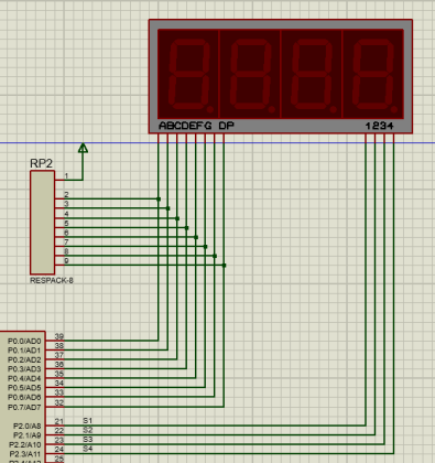
Function of display circuit: 4-bit common cathode nixie tube driving mode is adopted. The corresponding position 0 of port P2 is selected, that is, the corresponding nixie tube position 1 of port P0 can display the corresponding nixie tube segment. Responsible for displaying the hours and minutes of the clock.
3, Hardware system design
The simulation design of hardware schematic diagram is carried out by using Produce software.
Some circuits are shown in the figure:
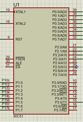
a. main control circuit: 80C51 single chip microcomputer
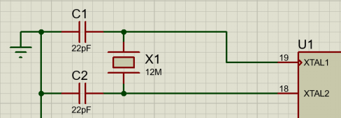
b. crystal oscillator circuit: the internal oscillation circuit of 89C51 single chip microcomputer is a high gain inverting amplifier. Leads XTAL1 and XTAL2 are the input of the inverting oscillation amplifier, the input of the internal clock working circuit and the output from the inverting oscillator respectively. The inverting amplifier can be configured as an on-chip oscillator.
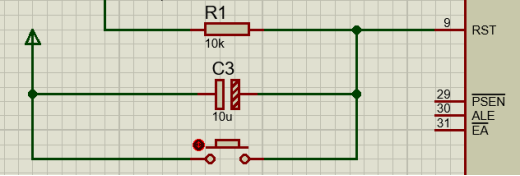
c. reset circuit: power on reset is adopted. After power on, RST will last for a period of high level due to capacitor charging, so as to realize power on reset operation. This can not only reset the single chip microcomputer, but also reset the peripheral equipment of the single chip microcomputer at the same time. When the program shows an error, the circuit can be reset at any time.
d. keyboard circuit: when the key is pressed, the corresponding pin is pulled down. After scanning, the key value is obtained and the key function program is executed. Therefore, different function programs will be executed by pressing the same key.
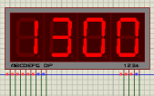
e. display circuit: it mainly displays the hour and minute of the digital electronic clock with a nixie tube.
4, Software system design
4.1 overall procedure flow chart
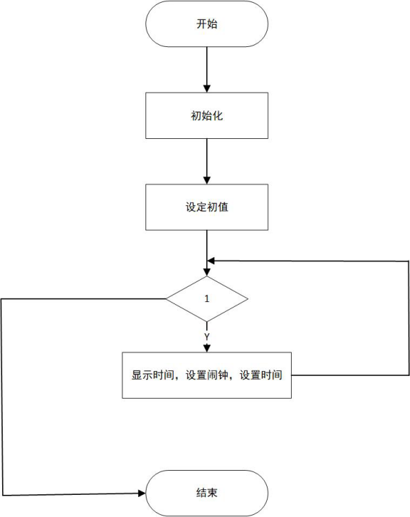
The flow chart of the main function: first initialize and set the initial value, and then call the relevant subroutines
4.2 main module program flow
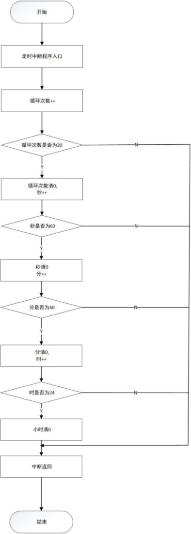
1. Call the interrupt service subroutine, and the number of cycles is + +. Because the timing time is 50ms, when the number of cycles is 20, the number of cycles is cleared to 0, second + +; Seconds is 60 minutes Plus + +, seconds clear 0; When it is divided into 60 hours, hour + +, distinguish 0; When the time is 24, the time is cleared to 0 and the interrupt returns.
2. First confirm whether the key for spring anti shake is pressed, and then judge the scanning key. Different keys trigger different functions.
V. source code
Partial code display:
#include<reg51.h>
#define tl 0xba;  // Macro definition TL initial value
#define th 0x3c;   // Macro definition th initial value

sbit speaker=P3^5;     		//Alarm output 	 Buzzer

unsigned char code led[]={0x3f,0x06,0x5b,0x4f,0x66,0x6d,0x7d,0x07,0x7f,0x6f};  //Code of numbers 0-9 displayed by nixie tube
unsigned char count0,second,minit,hour;	//Time hour minute second
unsigned int second1,minit1,hour1;//Alarm clock hours, minutes and seconds

//timenum1 is the number of times the key to adjust the time is pressed
//timenum2 is the number of times the key to adjust the alarm clock is pressed
//Is the alarm clock being set
//Is the time set
unsigned char timenum1,timenum2,f1,f2;
unsigned int dsflg;
unsigned char temp;

//Automatic generation of delay subroutine code burning software
void delay(void)
{
	unsigned int i;
	for(i=0;i<100;i++);
}
//50ms
//Nixie tube display
void display(void)
{

	P0=led[hour/10]; //p0 port data split display, ten digits at
	P2=0xFE;		 //Film selection P2 0
	delay();		  //delayed
	P2=0xFF;		  //Film selection pass

	P0=led[hour%10];   //p0 port data split number display, single bit at
	P2=0xFD;    //P2.1
	delay();
	P2=0xFF;

	P0=led[minit/10];   //p0 port data split number display, ten digits
	P2=0xFB;  //P2.2
	delay();
	P2=0xFF;

	P0=led[minit%10];   //p0 port data split display, divided bits
	P2=0xF7;  //P2.3
	delay();
	P2=0xFF;
}

//Scan key
void keyscan()
{
 	unsigned char temp;
  	P1=0xfe;     // Give P1 0 low level
  	temp=P1;
  	temp=temp&0xf0;     //Judgment P1 0 is there a key pressed in that column
  	if(temp!=0xf0)// Make sure that when a key is pressed
  	{
   	 	delay1(10);   //Delay subroutine for chattering elimination
		temp=P1;
    	temp=temp&0xf0; //Judge P1 again 0 is there a key pressed in that column
		if(temp!=0xf0)      //Make sure the key is pressed
		{
	  		temp=P1;     //Give the value of P1 to temp
			switch(temp)
	  		{
	    		case 0xee:    //p1.4 Ports
					timenum1++;	  	//Mark++
					TR1=0;     //Turn off the buzzer without starting T1
					f2=0;     //Enter the state of time adjustment
					if(timenum1==1||timenum2==1)	 //If timenum1==1, adjust the time
					{
						dsflg=0;    //Adjusting time
					}
					if(timenum1==3)	 If timenum1==4 sign out
					{
						TR1=1;     //Start T1
						timenum1=0;      //Set the number of keystrokes to zero
						dsflg=1;      //Exit adjustment time
						f2=1;     //Exit adjustment time
					}
					break;

	    		case 0xde:  //p1.5 ports
	    			//Adjust time
					if(timenum1==1)	 //If timenum1==1, adjust the time
	        		{
						hour++;		//Hours++
			 		}
					if(timenum1==2)	 //If timenum1==2, adjust the score
	        		{
			   			minit++;
			  		}
                  //Adjust the alarm clock
					if(timenum2==1)	 //If timenum2==1, adjust the time 	  alarm clock
	          		{
						hour1++;		//Hours++
			  		}
					if(timenum2==2)	 //If timenum2==2, adjust the score 	 alarm clock
	          		{
			   			minit1++;
			  		}
		     		break;

	    		case 0xbe:     //p1.6 ports
	     	     	speaker=1;  //The buzzer does not sound when the time is set
					if(timenum1==1)	 //If timenum1==1, adjust the time
	          		{
						hour--;		//Hours--
			  		}
					if(timenum1==2)	 //If timenum1==2, adjust the score
	          		{
			   			minit--;    //Minutes--
			  		}
			  	   //Adjust the alarm clock
					if(timenum2==1)	 //If timenum2==1, adjust the time 	  alarm clock
	          		{
						hour1--;		//Hours--
			  		}
					if(timenum2==2)	 //If timenum2==2, adjust the score 	 alarm clock
	          		{
			   			minit1--;
			  		}
		     		break;

	    		case 0x7e://p1.7
					timenum2++;	  //Mark++
					f1=0;    //Enter set alarm clock
					if(timenum2==1||timenum2==2)	//If timenum2=1, set the hour of the brain clock
					{
						dsflg=0;   //Adjusting time
	 				}
					if(timenum2==3)	//Exit if timenum2=3
					{
						timenum2=0;     //Set the number of keystrokes to zero
						dsflg=1;  //Exit adjustment time
						f1=1;     // Exit setting alarm clock
					}
		     		break;
	  		}

	  		while(temp!=0xf0)    //Judge whether the key pops up
	  		{
        		temp=P1;
        		temp=temp&0xf0;
	  		}
		}
  	}
}

//Key control time setting
void Keykonzhi()
{
	if(timenum1==1)	 //If timenum1==1, adjust the time
	{
		if(hour>23)	  //Limit
		{
			hour=0;
		}

		P0=led[hour/10];    //Show hours
		P2=0xFE;     //Hour ten P2 0
		delay();
		P2=0xFF;

		P0=led[hour%10]; //Show hours
		P2=0xFD;     //Hour bits P2 one
		delay();
		P2=0xFF;
	}

	if(timenum1==2)	 If timenum1==2 Score adjustment  //The following is the same method as time adjustment

	{
		if(minit>59)
		{
			minit=0;
		}

		P0=led[minit/10];
		P2=0xFB;   //Ten minutes P2 two
		delay();
		P2=0xFF;

		P0=led[minit%10];
		P2=0xF7;   //Minute bits P2 three
		delay();
		P2=0xFF;
	}
}

//set alarm
void almset()
{
	timenum1=0;
	if(timenum2==1)	//If timenum2==1, set the hour of the alarm clock
	{
		if(hour1>23)   //Limit
		{
			hour1=0;
		}

		P0=led[hour1/10];//Ten digits per hour
		P2=0xFE;//p2.0
		delay();
		P2=0xFF;

		P0=led[hour1%10];
		P2=0xFD;//p2. One hour digit display
		delay();
		P2=0xFF;
	}

	if(timenum2==2)	   //If timenum2==2, set the minutes of the alarm clock to be the same as the above hours
	{
		if(minit1>59)
		{
			minit1=0;
		}

		P0=led[minit1/10];//Display ten minutes
		P2=0xFB; //  p2.2
		delay();
		P2=0xFF;

		P0=led[minit1%10];//Display minute bits
		P2=0xF7;// p2.3
		delay();
		P2=0xFF;
	}
}

//Control the alarm clock (the alarm clock will ring when it reaches the set time)
void almkozi()
{
	if((hour1==hour)&&(minit1==minit)&&(second<4))
	{
		speaker=0;      //When the alarm clock is up, the buzzer rings
	 }
	if(minit==0&&second<4)
	{
		//The buzzer rings when the hour is announced
    	speaker=0;
	}

	if(second>4) //Controls the duration of the buzzer
	{
  		speaker=1;   //Turn off the buzzer
	}
}
Vi. display of test results
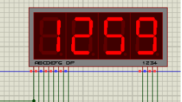
1. Clock display: the initial setting time is 12:59.
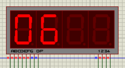
2 . Alarm clock timing: manually press the key to adjust the timing of the clock.
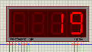
3. Alarm clock minute adjustment: manually press the key to adjust the minute of the clock.
4. Hour reporting: the buzzer will ring when the clock reaches the hour, so as to achieve the effect of time reporting.
7, Design summary
In the process of curriculum design, I further realized the importance of comprehensive professional knowledge and logical thinking to research problems. At the same time, I also mastered the basic methods of curriculum design more specifically. After continuous efforts, I finally completed the course design. Generally speaking, I learned a lot and knew the importance of integrating theory with practice. I encountered many difficulties in the design process, but I didn't give up. I consulted many relevant books, thought independently and learned from many excellent achievements of predecessors, and closely combined with the knowledge I learned. I believe this process has a positive impact on my future study and work, and has built a good platform. Through this design, I have a better understanding of this course, especially combined with the relevant professional knowledge learned in recent years, I have a more comprehensive understanding of each course. This will be of great help to my future study and work. The timing alarm clock circuit designed in this course can meet people's basic requirements. However, due to the limited knowledge level, there are some problems in this circuit. Although it can be solved by adding circuits, it is too complex and the existing level is limited. This design is not deeply involved. If you want to better improve the circuit, you need further efforts. If you have good opinions, I hope the teacher will give support and guidance.
The space is limited and only part of the content is written. If you want to obtain the source code and course design report, please stamp 👇 https://download.csdn.net/download/weixin_45699237/74791451
Schematic diagram of protues simulation 👇
https://download.csdn.net/download/weixin_45699237/74791672
Improved protues schematic diagram 👇