Introduction: The software transplanted with micro python with PWM function sent by MindMotion on November 22 was tested. Firstly, the output waveform can be tested on the two PWM channels (PA6 and PA7), but there are still differences between the signal parameters and settings: the spectrum of the output PWM signal is smaller than the set frequency, and the output waveform is just opposite to the set duty cycle.
Keywords: PWM, MindMotion, micropathon
§01 MM32 MicroPython
1, Background introduction
over the past weekend, MindMotion SuYong revised the version with PWM in the transplanted micropathon and sent the latest version:
Micro Python / mindmotion / firmware-2021-11-22.bin · Zhuo Qing / programming technology - Gitee.com
for this version Test mindmotion mm32f3277 micropathon - 2021-11-20 new PWM version Fix the existing problems. However, the main framework of the procedure has not changed. That is, the function of eight PWM channels is still completed with the help of two timers.
2, PWM function
according to the test the day before yesterday, we can know that the main pins and internal timer resources of PWM are as follows:
| PWM | timer | GPIO |
|---|---|---|
| PWM0 | TIM3 | PA6 |
| PWM1 | TIM3 | PA7 |
| PWM2 | TIM3 | PB0 |
| PWM3 | TIM3 | PB1 |
| PWM4 | TIM4 | PB6 |
| PWM5 | TIM4 | PB7 |
| PWM6 | TIM4 | PB8 |
| PWM7 | TIM4 | PB9 |
3, Download micro Python
1. Download micro Python
download the downloaded micro Python to Design mm32f3277 micro Python experimental board with SD card Then use STM32BOOTLOADER for REPL test.
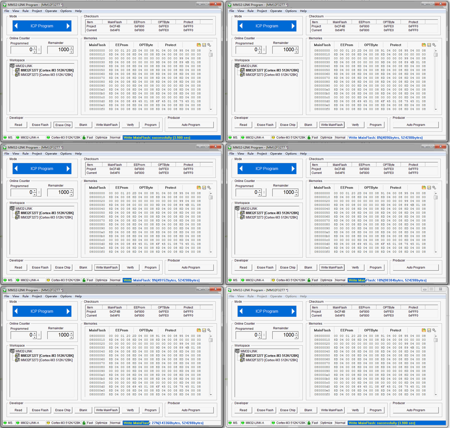
2. Power on test
after power on, the following is displayed on the REPL interface:
>> Open COM8, baud : 115200

[Y] sdcard ready.
[Y] file system on sdcard ready.
[Y] run the main.py on disk ...
[Y] done. 1
MicroPython v1.16 on 2021-11-22; MB_F3270 with MM32F3277G7P
>>>
§ 02 test PWM
1, Basic test
1. Test basic waveform
initialize PWM channels 0 and 1, occupy PA6 and PA7 respectively, and output the corresponding PWM waveform.
(1) Test code
from machine                import Pin,PWM
import utime

pwm0 = PWM(0, freq=10000, duty=200)
pwm1 = PWM(1, freq=10000, duty=500)

print("Test PWM.")
(2) Output waveform
measure the output waveform, as shown in the figure below:
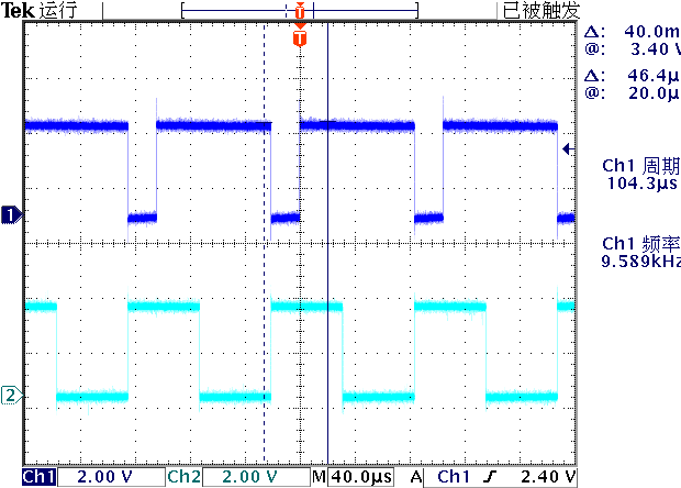
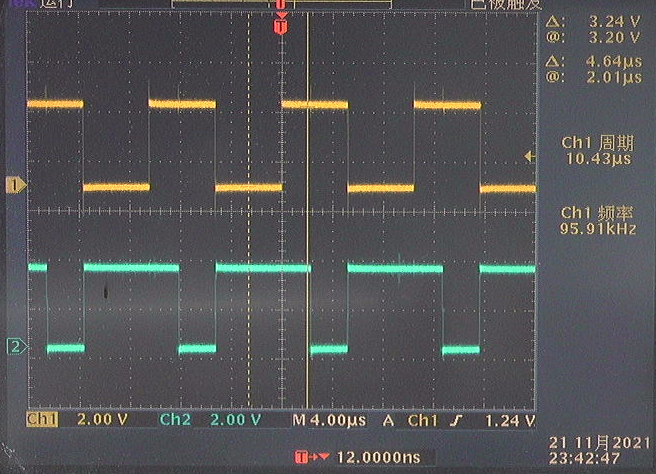
it can be seen that there is an error between this waveform and the set parameters:
- Frequency error: the actual PWM output frequency is 9.589, and the frequency of the signal measured by the frequency range of FLUKE45 digital multimeter is 9.5914kHz.
- Duty cycle error: set duty=200. The actual output is 800. The output waveform is reversed.
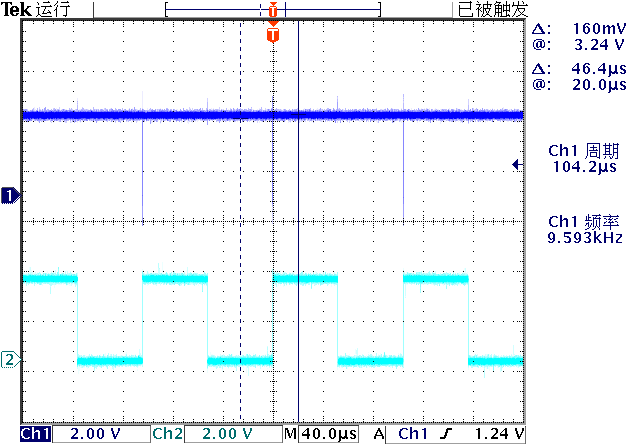
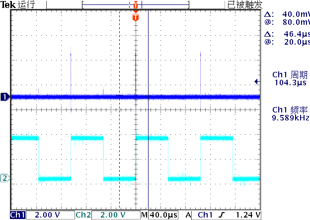
the following is the waveform corresponding to the duty of PWM0 set to 1999 respectively.
2. Dynamically change duty
(1) Test code
from machine                import Pin,PWM
import utime

pwm0 = PWM(0, freq=10000, duty=500)
pwm1 = PWM(1, freq=10000, duty=1)

print("Test PWM.")

duty = 1
dutyinc = 20
dir = 0

while True:

    if dir == 0:
        duty += dutyinc
        if duty >= 1000:
            duty = 999
            dir = 1
    else:
        if duty < dutyinc:
            duty = 1
            dir = 0
        else:
            duty -= dutyinc

    pwm1.duty(duty)

    utime.sleep_ms(100)
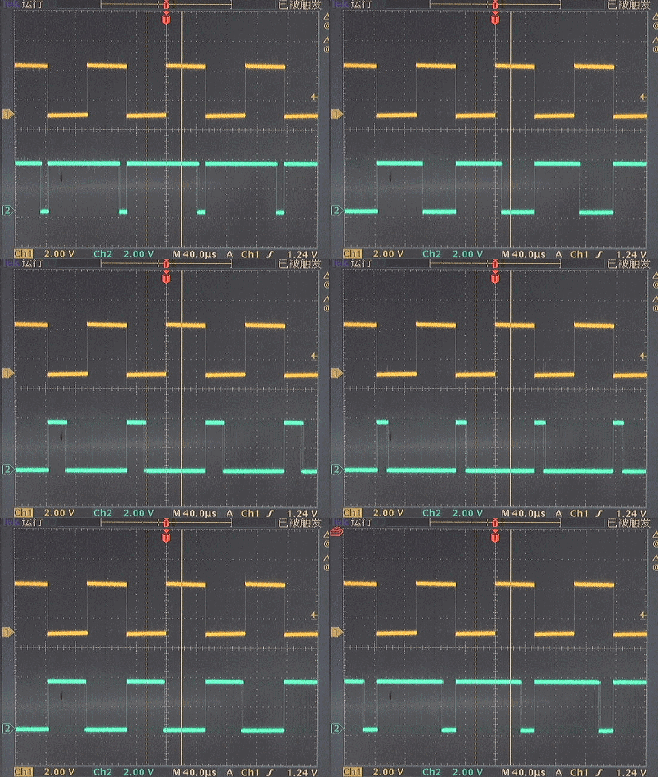
※ test summary ※
tested the software transplanted with micro python with PWM function sent by MindMotion on November 22. Firstly, the output waveform can be tested on two PWM channels (PA6 and PA7), but there are still differences between signal parameters and settings:
- The output frequency is smaller than the set frequency;
- The duty cycle of the output is just opposite to the setting.
■ links to relevant literature:
- Micro Python / mindmotion / firmware-2021-11-22.bin · Zhuo Qing / programming technology - Gitee.com
- Test mindmotion mm32f3277 micropathon - 2021-11-20 new PWM version
- Design mm32f3277 micro Python experimental board with SD card
● relevant chart links:
- Table 1-1 PWM resource allocation
- Figure 1.3.1 download the new version of micropthon to the beta
- Figure 2.1.1 PWM output waveform
- Figure 2.1.2 waveform corresponding to setting duty=1 for pwm0
- Figure 2.1.3 waveform corresponding to pwm0 setting duty=999
- Figure 2.1.4 dynamic change of duty cycle of PWM1
- Figure 3.1 setting the output waveform corresponding to 100kHz PWM
#!/usr/local/bin/python
# -*- coding: gbk -*-
#============================================================
# TESTPWM.PY                   -- by Dr. ZhuoQing 2021-11-22
#
# Note:
#============================================================

from machine                import Pin,PWM
import utime

pwm0 = PWM(0, freq=100000, duty=500)
pwm1 = PWM(1, freq=10000, duty=1)

print("Test PWM.")

duty = 1
dutyinc = 20
dir = 0

while True:

    if dir == 0:
        duty += dutyinc
        if duty >= 1000:
            duty = 999
            dir = 1
    else:
        if duty < dutyinc:
            duty = 1
            dir = 0
        else:
            duty -= dutyinc


    pwm1.duty(duty)

    utime.sleep_ms(100)


#------------------------------------------------------------
#        END OF FILE : TESTPWM.PY
#============================================================