preface
The part of the combinational circuit can be designed according to the function and the given port. It should be noted that
1. Avoid generating latch. If there is a latch in the circuit after compilation, you need to check the code to eliminate the latch.
2. Don't use the high resistance state easily. The concept of high resistance state may not be learned when realizing the early components. The first few components usually don't} produce this problem. When you encounter this problem later, you will specify when to use the high resistance state.
Combinational circuits can be implemented using either the always statement or the assign statement. The resource consumption and maximum delay of the circuit generated by the two statements may be different. Try two different writing methods for comparison, which will also affect the performance of the final implementation model machine.
I Instruction decoder
1. Function
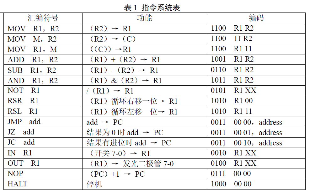
When enable en is valid as 1, the instruction code ir is converted into an instruction signal, and the corresponding instruction signal is output as 1.
2. Instruction code table
3. Code
The always statement is executed continuously, so all signals are set to 0 at the beginning of each time. Judge which instruction output signal is 1 according to the coding. There are three MOV instructions in the instruction table, which are defined as MOVA, MOVB and MOVC respectively.
module instruction_decoder(EN,ir,MOVA,MOVB,MOVC,ADD,SUB,AND1,NOT1,RSR,RSL,JMP,JZ,JC, IN1,OUT1,NOP,HALT);
	input [7:0] ir;
	input EN;
	output MOVA,MOVB,MOVC,ADD,SUB,AND1,NOT1,RSR,RSL,JMP,JZ,JC,IN1,OUT1,NOP,HALT;
	reg MOVA,MOVB,MOVC,ADD,SUB,AND1,NOT1,RSR,RSL,JMP,JZ,JC,IN1,OUT1,NOP,HALT;
	always@(ir,EN)
	begin
	MOVA=0;MOVB=0;MOVC=0;ADD=0;SUB=0;AND1=0;NOT1=0;RSR=0;RSL=0;JMP=0;JZ=0;JC=0;IN1=0;           OUT1=0;NOP=0;HALT=0;
		if (EN)
		begin
			if(ir[7:4]==4'b1100)
			begin
				if(ir[3]&ir[2]) MOVB=1;
				else if(ir[1]&ir[0]) MOVC=1;
				else MOVA=1'b1;
			end
			else if(ir[7:4]==4'b1001) ADD=1;
			else if(ir[7:4]==4'b0110) SUB=1;
			else if(ir[7:4]==4'b1011) AND1=1;
			else if(ir[7:4]==4'b0101) NOT1=1;
			else if(ir[7:4]==4'b1010)
			begin
				if(~ir[1]&~ir[0]) RSR=1;
				else RSL=1;
			end
			else if(ir[7:4]==4'b0011)
			begin
				JC=ir[1];
				JZ=ir[0];
				JMP=!ir[1]&&!ir[0];
			end
			else if(ir[7:4]==4'b0010)IN1=1;
			else if(ir[7:4]==4'b0100)OUT1=1;
			else if(ir[7:4]==4'b0111)NOP=1;
			else if(ir[7:4]==4'b1000) HALT=1;
			else ;
		end
		else ;
	end
endmodule
The writing method of assign statement is similar to MOV instruction and other instructions.
...
assign MOVA=ir[7]&&ir[6]&&!ir[5]&&ir![4]&&!MOVB&&!MOVC //1100MOV instruction and not MOVB, MOVC
assign MOVB=ir[7]&&ir[6]&&!ir[5]&&ir![4]&&ir[3]&&ir[2]; //110011XX
assign MOVC=ir[7]&&ir[6]&&!ir[5]&&ir![4]&&ir[1]&&ir[0]; //1100XX11
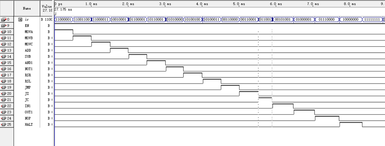
...4. Function simulation
Verify whether each command signal can be output correctly.
II ALU
1. Function
m and s are operation control signals, a and b are data input, cf and zf are state output, and t is data output.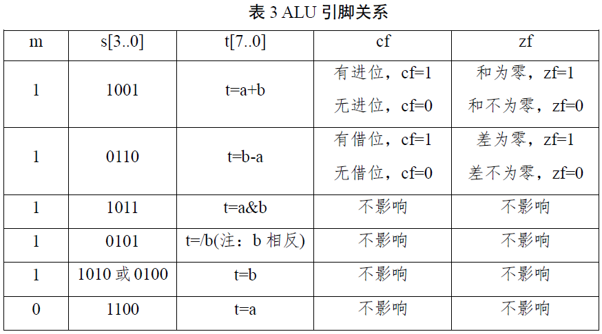
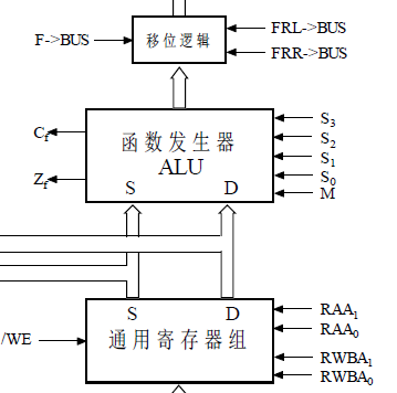
Pay attention to the position and port of the function generator. a and b are connected to the output of general registers s and D; t outputs the result to the shift logic; s3-s0 is actually the first four bits of the instruction code according to the menu; m is sent by the control signal generator; The results of cf and zf are given to the status register.
2. Code
module ALU(a,b,s,m,t,cf,zf);
	input [7:0] a;
	input [7:0] b;
	input m;
	input [3:0] s;
	output cf,zf;
	output [7:0] t;
	reg cf,zf;
	reg [7:0] t;
	always@(m,s,a,b)
	begin
		t=8'b0;
		cf=1'b0;
		zf=1'b0;
		if(m==1)
		begin
			if(s==4'b1001)
			begin
				{cf,t}=a+b;
				if(t==0) zf=1;
				else zf=1'b0;
			end
			else if(s==4'b0110)
			begin
				{cf,t}=b-a;
				if(t==0) zf=1'b1;
			else zf=0;
			end
			else if(s==4'b1011) t=a&b;
			else if(s==4'b0101) t=~b;
			else if(s==4'b1010 || s==4'b0100) t=b;
			else t=a;
		end
		else t=a;
	end
endmodule
3. Function simulation
Verify the function one by one and the output is correct.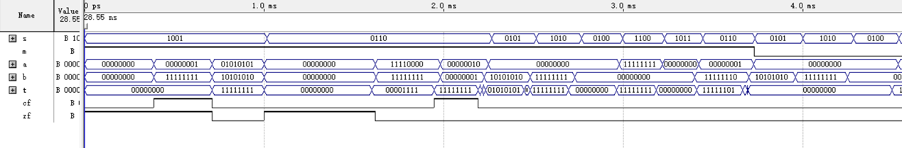
The instruction decoder and ALU are relatively simple. The latter parts will focus on several places that are easy to make mistakes and need attention.