Movable gear
First effect

It's realized with canas in js. The actual effect is that the gear will move. It's still interesting. It's perfect with some music.
Problem analysis
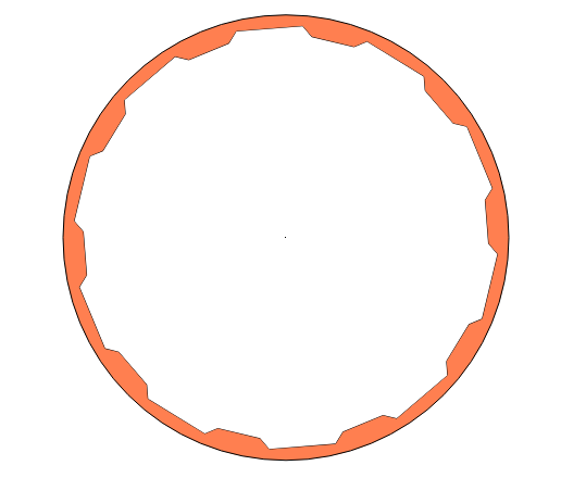
js inside the canas knowledge, you can refer to https://www.runoob.com/html/html5-canvas.html , I won't introduce it here. We can see from the graphics that we have two types of gears, one is orange in the outer ring and the other is blue in the inner ring.
Analysis of large gear
The outer ring of the big gear is a circle. Just draw it directly with arc. The main problem now is the realization of the inner ring. Let's look at the outer ring with larger teeth:
Analyze a tooth and establish a coordinate system, as shown in the following figure:
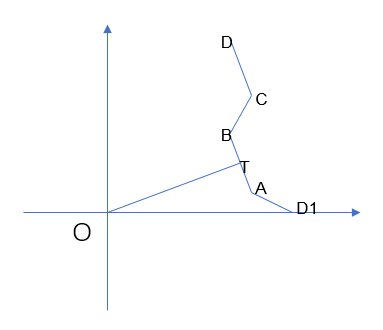
It can be seen that D1ABCD can form a tooth of the smallest unit. We can get the inner tooth of the outer ring as long as we rotate the tooth for circular rotation. Now we assume that the O center coordinate is (x,y), the inner circle radius OT is r1, the outer circle radius OD1=r2, and the corresponding center angle of each sawtooth and the gap between sawteeth is w0, where T is the midpoint of AB, AT=BT=d. under these conditions, The following coordinates can be easily obtained:
x
T
=
r
1
∗
c
o
s
(
w
0
/
2
)
+
x
x_T=r_1*cos(w_0/2)+x
xT=r1∗cos(w0/2)+x
y
T
=
r
1
∗
s
i
n
(
w
0
/
2
)
+
y
y_T=r_1*sin(w_0/2)+y
yT=r1∗sin(w0/2)+y
Then the A and B coordinates can be obtained
x
A
=
r
1
∗
c
o
s
(
w
0
/
2
)
+
x
+
d
∗
s
i
n
(
w
0
/
2
)
x_A=r_1*cos(w_0/2)+x+d*sin(w_0/2)
xA=r1∗cos(w0/2)+x+d∗sin(w0/2)
y
A
=
r
1
∗
s
i
n
(
w
0
/
2
)
+
y
−
d
∗
c
o
s
(
w
0
/
2
)
y_A=r_1*sin(w_0/2)+y-d*cos(w_0/2)
yA=r1∗sin(w0/2)+y−d∗cos(w0/2)
x
B
=
r
1
∗
c
o
s
(
w
0
/
2
)
+
x
−
d
∗
s
i
n
(
w
0
/
2
)
x_B=r_1*cos(w_0/2)+x-d*sin(w_0/2)
xB=r1∗cos(w0/2)+x−d∗sin(w0/2)
y
B
=
r
1
∗
s
i
n
(
w
0
/
2
)
+
y
+
d
∗
c
o
s
(
w
0
/
2
)
y_B=r_1*sin(w_0/2)+y+d*cos(w_0/2)
yB=r1∗sin(w0/2)+y+d∗cos(w0/2)
Both point C and point D are on the outer circle, so the coordinates are:
x
C
=
r
2
∗
c
o
s
(
w
0
)
+
x
x_C=r_2*cos(w_0)+x
xC=r2∗cos(w0)+x
y
C
=
r
2
∗
s
i
n
(
w
0
)
+
y
y_C=r_2*sin(w_0)+y
yC=r2∗sin(w0)+y
x
D
=
r
2
∗
c
o
s
(
2
∗
w
0
)
+
x
x_D=r_2*cos(2*w_0)+x
xD=r2∗cos(2∗w0)+x
y
D
=
r
2
∗
s
i
n
(
2
∗
w
0
)
+
y
y_D=r_2*sin(2*w_0)+y
yD=r2∗sin(2∗w0)+y
In order to make the gear rotate, if there is no initial angle, it is not necessarily 0, that is, D1 is not on the coordinate axis, and there is an included angle. For the above coordinates, you only need to add the internal angle to the initial angle w0. According to this idea, js is used to realize the code as follows:
function gear1(ctx,x,y,r1,r2,n,d,p0){
         /*
         ctx: Object for drawing
         x,y:Coordinates of the center of the circle
         r1:Gear inner radius
         r2:Radius of gear outer circle
         n: Gear and interval bisector quantity
         d: Half distance of tooth protrusion
         p0:Initial angle
         */

         var x0=x+r2;
         var y0=y;
         //Center angle corresponding to each tooth
         var w0=2*Math.PI/n;
         var w1=p0;
         var w2=w0/2;

         var rw=10;
         ctx.beginPath();
         ctx.arc(x,y,r2+10,0,2*Math.PI);
         ctx.fillStyle="#ff7f50";
         ctx.fill();
         ctx.stroke();

         ctx.beginPath();
         ctx.arc(x,y,rw,0,2*Math.PI);
         ctx.stroke();

         ctx.beginPath();
         //Move to initial position
         var Ax=r2*Math.cos(w1)+x;
	     var Ay=r2*Math.sin(w1)+y;
	     ctx.moveTo(Ax,Ay);

         for(var i=0;i<n/2;i++){
             w2=w1+w0/2;//Initial included angle
             //Coordinate of point A
	     var Ax=r1*Math.cos(w2)+d*Math.sin(w2)+x;
	     var Ay=r1*Math.sin(w2)-d*Math.cos(w2)+y;
	     //Coordinate of point B
	     var Bx=r1*Math.cos(w2)-d*Math.sin(w2)+x;
	     var By=r1*Math.sin(w2)+d*Math.cos(w2)+y;
	     //Coordinate of point C
	     var w1=w1+w0;
	     var Cx=r2*Math.cos(w1)+x;
	     var Cy=r2*Math.sin(w1)+y;
	     //D-point coordinates
	     var w1=w1+w0;
	     var Dx=r2*Math.cos(w1)+x;
	     var Dy=r2*Math.sin(w1)+y;

	     //Connect
	     ctx.lineTo(Ax,Ay);
	     ctx.lineTo(Bx,By);
	     ctx.lineTo(Cx,Cy);
	     ctx.lineTo(Dx,Dy);

         }

         ctx.stroke();
         ctx.fillStyle="#ffffff";
         ctx.fill();

      }
Pinion analysis
The pinion is similar to the big gear, but the teeth of the pinion are convex, so the coordinate system analysis is established as follows:
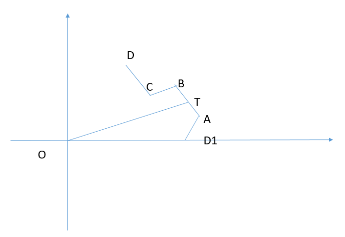
It can be seen that D1ABCD can form a tooth of the smallest unit. We can get the inner tooth of the outer ring as long as we rotate the tooth for circular rotation. Now we assume that the O center coordinate is (x,y), the inner circle radius OD1 is r1, the outer circle radius OT=r2, and the corresponding center angle of each sawtooth and the gap between sawteeth is w0, where T is the midpoint of AB, AT=BT=d. under these conditions, The following coordinates can be easily obtained:
x
T
=
r
2
∗
c
o
s
(
w
0
/
2
)
+
x
x_T=r_2*cos(w_0/2)+x
xT=r2∗cos(w0/2)+x
y
T
=
r
2
∗
s
i
n
(
w
0
/
2
)
+
y
y_T=r_2*sin(w_0/2)+y
yT=r2∗sin(w0/2)+y
Then the A and B coordinates can be obtained
x
A
=
r
2
∗
c
o
s
(
w
0
/
2
)
+
x
+
d
∗
s
i
n
(
w
0
/
2
)
x_A=r_2*cos(w_0/2)+x+d*sin(w_0/2)
xA=r2∗cos(w0/2)+x+d∗sin(w0/2)
y
A
=
r
2
∗
s
i
n
(
w
0
/
2
)
+
y
−
d
∗
c
o
s
(
w
0
/
2
)
y_A=r_2*sin(w_0/2)+y-d*cos(w_0/2)
yA=r2∗sin(w0/2)+y−d∗cos(w0/2)
x
B
=
r
2
∗
c
o
s
(
w
0
/
2
)
+
x
−
d
∗
s
i
n
(
w
0
/
2
)
x_B=r_2*cos(w_0/2)+x-d*sin(w_0/2)
xB=r2∗cos(w0/2)+x−d∗sin(w0/2)
y
B
=
r
2
∗
s
i
n
(
w
0
/
2
)
+
y
+
d
∗
c
o
s
(
w
0
/
2
)
y_B=r_2*sin(w_0/2)+y+d*cos(w_0/2)
yB=r2∗sin(w0/2)+y+d∗cos(w0/2)
Both point C and point D are on the outer circle, so the coordinates are:
x
C
=
r
1
∗
c
o
s
(
w
0
)
+
x
x_C=r_1*cos(w_0)+x
xC=r1∗cos(w0)+x
y
C
=
r
1
∗
s
i
n
(
w
0
)
+
y
y_C=r_1*sin(w_0)+y
yC=r1∗sin(w0)+y
x
D
=
r
1
∗
c
o
s
(
2
∗
w
0
)
+
x
x_D=r_1*cos(2*w_0)+x
xD=r1∗cos(2∗w0)+x
y
D
=
r
1
∗
s
i
n
(
2
∗
w
0
)
+
y
y_D=r_1*sin(2*w_0)+y
yD=r1∗sin(2∗w0)+y
In order to make the gear rotate, if there is no initial angle, it is not necessarily 0, that is, D1 is not on the coordinate axis, and there is an included angle. For the above coordinates, you only need to add the internal angle to the initial angle w0. According to this idea, js is used to realize the code as follows:
function gear(ctx,x,y,r1,r2,n,d,p0){
	      /*
         ctx: Object for drawing
         x,y:Coordinates of the center of the circle
         r1:Gear inner radius
         r2:Radius of gear outer circle
         n: Gear and interval bisector quantity
         d: Half distance of tooth protrusion
         p0:Initial angle
         */

         var x0=x+r2;
         var y0=y;

         var w0=2*Math.PI/n;

         var w1=p0;
         var w2=w0/2;

         var rw=10;

         ctx.beginPath();
		 //Move to initial position D1
         var D1x=r1*Math.cos(w1)+x;
	     var D1y=r1*Math.sin(w1)+y;

	     ctx.moveTo(D1x,D1y);

         for(var i=0;i<n/2;i++){
             w2=w1+w0/2;
             //Coordinate point A
	         var Ax=r2*Math.cos(w2)+d*Math.sin(w2)+x;
	         var Ay=r2*Math.sin(w2)-d*Math.cos(w2)+y;
	         //Coordinate of point B
	         var Bx=r2*Math.cos(w2)-d*Math.sin(w2)+x;
	         var By=r2*Math.sin(w2)+d*Math.cos(w2)+y;

	         var w1=w1+w0;
			 //Coordinate of point C
	         var Cx=r1*Math.cos(w1)+x;
	         var Cy=r1*Math.sin(w1)+y;

	         var w1=w1+w0;
			 //D-point coordinates
	         var Dx=r1*Math.cos(w1)+x;
	         var Dy=r1*Math.sin(w1)+y;

	         //Connect
	         ctx.lineTo(Ax,Ay);
	         ctx.lineTo(Bx,By);
	         ctx.lineTo(Cx,Cy);
	         ctx.lineTo(Dx,Dy);

         }

         ctx.stroke();
         ctx.fillStyle="#00BFFF";
         ctx.closePath();
         ctx.fill();

         ctx.beginPath();
         ctx.fillStyle="#808080";
         ctx.arc(x,y,rw,0,2*Math.PI);//Inner small circle
         ctx.closePath();
         ctx.fill();
      }
Gear position
It can be seen that the position of the center of the circle forms an equilateral triangle, so we can draw the following coordinates:
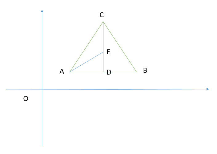
Assuming that the coordinates of a are (x,y) and the side length of the equilateral triangle is a, we can easily find the coordinates of other points:
x
B
=
x
+
a
x_B=x+a
xB=x+a
y
B
=
y
y_B=y
yB=y
x
C
=
x
+
a
2
x_C=x+\frac{a}{2}
xC=x+2a
y
C
=
y
+
a
∗
s
i
n
(
π
3
)
y_C=y+a*sin(\frac{π}{3})
yC=y+a∗sin(3π)
x
D
=
x
+
a
2
x_D=x+\frac{a}{2}
xD=x+2a
y
D
=
y
+
a
2
∗
t
a
n
(
π
6
)
y_D=y+\frac{a}{2}*tan(\frac{π}{6})
yD=y+2a∗tan(6π)
From this, we can form this Code:
  function load(){
          n=0;

          setInterval(function(){
		          var c=document.getElementById("mycanvas");
			      var ctx=c.getContext("2d");
			      ctx.fillStyle="#00BFFF";
			      ctx.clearRect(0,0,c.width,c.height);

			      var bl=200;
			      var x1=200;//Coordinate of point A
			      var y1=200;

			      var x2=x1+bl;//Coordinate of point B
			      var y2=y1;

			      var x3=x1+bl*Math.cos(Math.PI/3);//Coordinate of point C
			      var y3=y1+bl*Math.sin(Math.PI/3);

			      var x4=x1+bl*Math.cos(Math.PI/3);//D-point coordinates
			      var y4=y1+Math.tan(Math.PI/6)*bl/2;

			      p0=2*Math.PI/64*n;
			      p1=-p0/2;
			      p2=-p0/5+2*Math.PI/32*2;
			      gear1(ctx,x3,y4,185,195,80,5,p2);
			      gear(ctx,x1,y1,70,80,32,5,p1);
			      gear(ctx,x2,y2,70,80,32,5,p1);
			      gear(ctx,x3,y3,70,80,32,5,p1);
			      gear(ctx,x3,y4,35,45,16,5,p0);

                  n++;
				  if(n==64){
                      n=0;
                   }

          },20);
		  }
Explain the relationship between the number of teeth and the angle. The outer ring has 40 teeth (80 parts), the same three inside have 16 teeth (32 parts), and the center gear has 8 teeth (16 parts). Therefore, the number of teeth ratio is 5:2:1, and the speed with more teeth is slow. Therefore, their angular speed ratio should be 1:2:5. Of course, the initial angle should be adjusted according to the actual situation to make the gears mesh together, Finally, post the overall Code:
<!DOCTYPE HTML>
<html>
  <head>

    <title>ta</title>
	<meta http-equiv="pragma" content="no-cache">
	<meta http-equiv="cache-control" content="no-cache">
	<meta http-equiv="expires" content="0">
	<meta http-equiv="keywords" content="keyword1,keyword2,keyword3">
	<meta http-equiv="description" content="This is my page">
	<!--
	<link rel="stylesheet" type="text/css" href="styles.css">
	-->
  </head>

  <script type="text/javascript">
  function load(){
          n=0;

          setInterval(function(){
		          var c=document.getElementById("mycanvas");
			      var ctx=c.getContext("2d");
			      ctx.fillStyle="#00BFFF";
			      ctx.clearRect(0,0,c.width,c.height);

			      var bl=200;
			      var x1=200;//Coordinate of point A
			      var y1=200;

			      var x2=x1+bl;//Coordinate of point B
			      var y2=y1;

			      var x3=x1+bl*Math.cos(Math.PI/3);//Coordinate of point C
			      var y3=y1+bl*Math.sin(Math.PI/3);

			      var x4=x1+bl*Math.cos(Math.PI/3);//D-point coordinates
			      var y4=y1+Math.tan(Math.PI/6)*bl/2;

			      p0=2*Math.PI/64*n;
			      p1=-p0/2;
			      p2=-p0/5+2*Math.PI/32*2;
			      gear1(ctx,x3,y4,185,195,80,5,p2);
			      gear(ctx,x1,y1,70,80,32,5,p1);
			      gear(ctx,x2,y2,70,80,32,5,p1);
			      gear(ctx,x3,y3,70,80,32,5,p1);
			      gear(ctx,x3,y4,35,45,16,5,p0);

                  n++;
				  if(n==64){
                      n=0;
                   }

          },20);
		  }

      function gear(ctx,x,y,r1,r2,n,d,p0){
	      /*
         ctx: Object for drawing
         x,y:Coordinates of the center of the circle
         r1:Gear inner radius
         r2:Radius of gear outer circle
         n: Gear and interval bisector quantity
         d: Half distance of tooth protrusion
         p0:Initial angle
         */

         var x0=x+r2;
         var y0=y;

         var w0=2*Math.PI/n;

         var w1=p0;
         var w2=w0/2;

         var rw=10;

         ctx.beginPath();
		 //Move to initial position D1
         var D1x=r1*Math.cos(w1)+x;
	     var D1y=r1*Math.sin(w1)+y;

	     ctx.moveTo(D1x,D1y);

         for(var i=0;i<n/2;i++){
             w2=w1+w0/2;
             //Coordinate of point A
	         var Ax=r2*Math.cos(w2)+d*Math.sin(w2)+x;
	         var Ay=r2*Math.sin(w2)-d*Math.cos(w2)+y;
	         //Coordinate of point B
	         var Bx=r2*Math.cos(w2)-d*Math.sin(w2)+x;
	         var By=r2*Math.sin(w2)+d*Math.cos(w2)+y;

	         var w1=w1+w0;
			 //Coordinate of point C
	         var Cx=r1*Math.cos(w1)+x;
	         var Cy=r1*Math.sin(w1)+y;

	         var w1=w1+w0;
			 //D-point coordinates
	         var Dx=r1*Math.cos(w1)+x;
	         var Dy=r1*Math.sin(w1)+y;

	         //Connect
	         ctx.lineTo(Ax,Ay);
	         ctx.lineTo(Bx,By);
	         ctx.lineTo(Cx,Cy);
	         ctx.lineTo(Dx,Dy);

         }

         ctx.stroke();
         ctx.fillStyle="#00BFFF";
         ctx.closePath();
         ctx.fill();

         ctx.beginPath();
         ctx.fillStyle="#808080";
         ctx.arc(x,y,rw,0,2*Math.PI);//Inner small circle
         ctx.closePath();
         ctx.fill();
      }

       function gear1(ctx,x,y,r1,r2,n,d,p0){
         /*
         ctx: Object for drawing
         x,y:Coordinates of the center of the circle
         r1:Gear inner radius
         r2:Radius of gear outer circle
         n: Gear and interval bisector quantity
         d: Half distance of tooth protrusion
         p0:Initial angle
         */

         var x0=x+r2;
         var y0=y;
         //Center angle corresponding to each tooth
         var w0=2*Math.PI/n;

         var w1=p0;
         var w2=w0/2;


         var rw=10;
         ctx.beginPath();
         ctx.arc(x,y,r2+10,0,2*Math.PI);
         ctx.fillStyle="#ff7f50";
         ctx.fill();
         ctx.stroke();

         ctx.beginPath();
         ctx.arc(x,y,rw,0,2*Math.PI);
         ctx.stroke();

         ctx.beginPath();
         //Move to initial position
         var D1x=r2*Math.cos(w1)+x;
	     var D1y=r2*Math.sin(w1)+y;

	     ctx.moveTo(D1x,D1y);

         for(var i=0;i<n/2;i++){
             w2=w1+w0/2;//Initial included angle
             //Coordinate of point A
	     var Ax=r1*Math.cos(w2)+d*Math.sin(w2)+x;
	     var Ay=r1*Math.sin(w2)-d*Math.cos(w2)+y;
	     //Coordinate of point B
	     var Bx=r1*Math.cos(w2)-d*Math.sin(w2)+x;
	     var By=r1*Math.sin(w2)+d*Math.cos(w2)+y;
	     //Coordinate of point C
	     var w1=w1+w0;
	     var Cx=r2*Math.cos(w1)+x;
	     var Cy=r2*Math.sin(w1)+y;
	     //D-point coordinates
	     var w1=w1+w0;
	     var Dx=r2*Math.cos(w1)+x;
	     var Dy=r2*Math.sin(w1)+y;

	     //Connect
	     ctx.lineTo(Ax,Ay);
	     ctx.lineTo(Bx,By);
	     ctx.lineTo(Cx,Cy);
	     ctx.lineTo(Dx,Dy);

         }

         ctx.stroke();
         ctx.fillStyle="#ffffff";
         ctx.fill();


      }

  </script>


  <body onload="load()">

       <canvas id="mycanvas" width="800" height="800"></canvas>


  </body>
</html>