MSP430F5529 LaunchPad™ Development Kit
(MSP‑EXP430F5529LP)
Hard knowledge
USCI communication module
Universal serial communication interface (usci) module supports multiple serial communication modes, and different usci modules support different communication modes. Each different usci module is named with different letters, such as USCI_A,USCI_B et al. If more than one same usci module is implemented on an MSP430 single chip microcomputer, these modules will be named with increasing numbers. For example, when an MSP430 MCU supports two USCIS_ A module, these two modules should be named USCI_A0 and USCI_A1. For details, refer to the data manual of the relevant chip to determine which usci communication modules the chip has.
USCI_ The ax module supports the following modes:
UART communication mode;
IrDA communication mode with pulse shaping;
LIN communication mode with automatic baud rate detection;
SPI communication mode.
USCI_ The BX module supports the following communication modes:
I2C communication mode;
SPI communication mode.
UART mode of USCI
Asynchronous serial communication (UART) has the following characteristics:
odd check, even check or no check can be used to transmit 7-bit or 8-bit data;
independent transmit and receive shift registers;
independent transmit and receive buffer registers;
support the data sending and receiving mode of lowest priority or highest priority;
built in multiprocessor system, including line idle and address bit communication protocol;
wake up MSP430 MCU from low power consumption mode through effective start bit detection;
programmable baud rate with frequency division factor of integer or decimal;
it has status flag bits for detecting or eliminating errors;
it has status flag bits for address detection;
it has independent sending and receiving interrupt capability.
In UART mode, usci_ The structure of ax is shown in the figure.
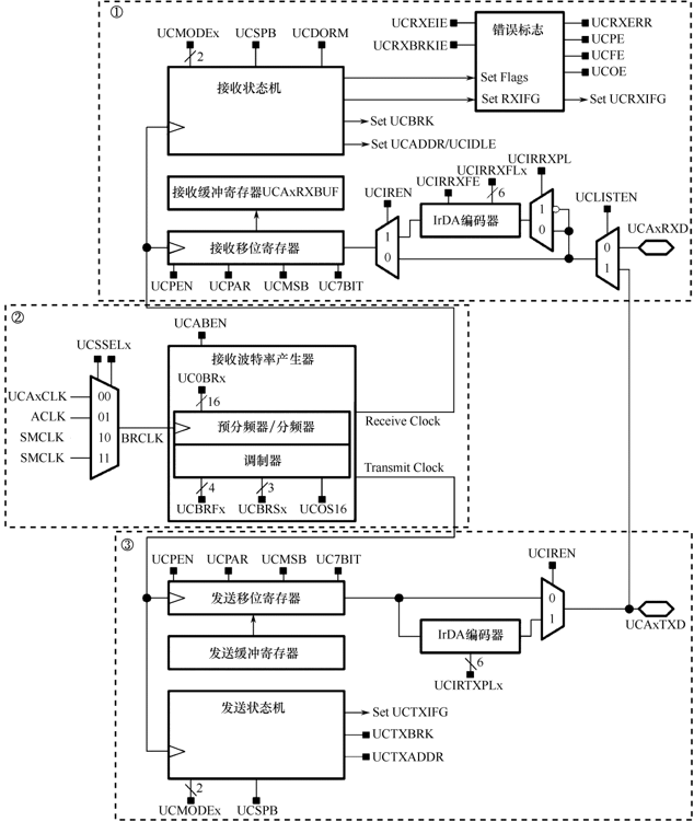
1. USCI initialization and reset
The USCI module can be reset by generating a PUC reset signal or setting the UCSWRST control bit. After a PUC reset signal is generated, the system can automatically set the UCSWRST control bit to keep the USCI module in the reset state. If UCSWRST controls the position bit, it will reset the UCRXIE, UCTXIE, UCRXIFG, UCRXERR, UCBRK, UCPE, UCOE, UCFE, UCSTOE and UCBTOE registers and set the UCTXIFG interrupt flag bit. Clear the UCSWRST control bit before USCI module can work.
Therefore, the USCI module can be initialized or reconfigured as follows:
① Set the UCSWRST control bit;
② When UCSWRST=1, initialize all USCI registers (including UCTxCTL1);
③ Configure the corresponding pin port as UART communication function;
④ The software clears the UCSWRST control bit;
⑤ The interrupt is enabled by setting the receive or transmit interrupt enable control registers UCRXIE and UCTXIE or one of them.
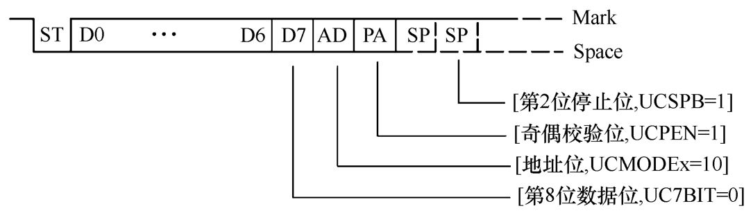
2. Asynchronous communication character format
As shown in the figure, the asynchronous communication character format consists of five parts: a start bit, 7 or 8 data bits, an odd / even / no check bit, an address bit and one or two stop bits. Among them, the user can set the number of data bits and stop bits through software, and can also set the presence or absence of parity bits. The transmission rate is determined by selecting the data of clock source and baud rate register. The UCMSB control bit is used to set the transmission direction and select whether the lowest bit or the highest bit is sent first. Generally, for UART communication, select to send the lowest bit first.
3. Asynchronous multi machine communication mode
When two devices communicate asynchronously, multi machine communication protocol is not required. When three or more devices communicate, USCI supports two multi machine communication modes, namely, line idle and address bit multi machine mode. Information is transmitted from a specified source to one or more destination locations in a multi frame data block. On the same serial link, multiple processors can exchange information in these formats to realize effective data transmission between multiprocessor communication systems. The UCMODEx control bit of the control register can be used to determine these two modes, which have the functions of wake-up transmission, address characteristics and activation. In the two multiprocessor modes, the USCI data exchange process can be realized by data query or interrupt.
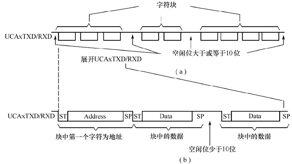
(1) Line idle multi machine mode
When the UCMODEx control bit is configured as 01, USCI selects the line idle multi machine mode, as shown in figure 7.1.3. In this mode, the data blocks on the transmission and reception data lines are divided by idle time. Figure (a) is the overall schematic diagram of data block transmission, and figure (b) is the schematic diagram of character transmission in each data block. In figure (a), if more than 10 1's are received after one or two stop bits of the character, it indicates that the receiving line is detected to be idle. After recognizing that the line is idle, the baud rate generator will be turned off and will not be restarted until the next start bit is detected. When an idle line is detected, the UCIDLE flag is set. In figure (b), the idle time of the line between each two data blocks shall be less than 10 idle cycles, so that the data can be transmitted correctly and normally.
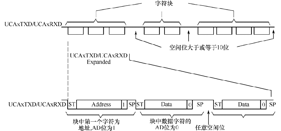
(2) Address bit multi machine mode
When the UCMODEx control bit is configured to 10, USCI selects the address bit multi machine mode. In this mode, the character contains an additional bit as an address flag. The format of address bit multi machine mode is shown in the figure. The first character of the data block has a set address bit to indicate that the character is an address. The USCI module will set the UCADDR flag bit when the received character address position bit is and transferred to the UCAxRXBUF receive buffer register.
4. Automatic baud rate detection
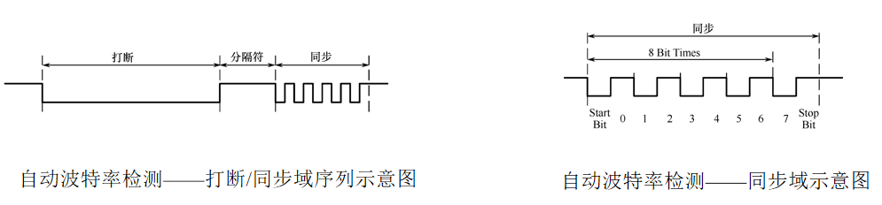
When the UCMODEx control bit is configured to 11, UART mode with automatic baud rate selection is selected. For UART automatic baud rate detection mode, there will be a synchronization sequence including interrupt and synchronization domain in front of the data frame. When 11 or more zeros are detected on the bus, it is recognized as a bus interrupt. If the length of the bus interrupt exceeds the 21 bit time length, the interrupt timeout error flag UCBTOE will be set. USCI cannot send data when receiving an interrupt or synchronization domain. After the synchronization domain is interrupted, the schematic diagram is shown on the left.
In one byte, the synchronization field contains data 055h, as shown in the right figure. Synchronization is based on the time measurement between the first falling edge and the last falling edge of this mode. If the automatic baud rate detection function is enabled by setting the UCABDEN control bit, the baud rate generator is usually used for time measurement. Otherwise, in this mode, only receive and do not measure. The measured results will be transferred to the baud rate control registers (UCAxBR0, UCAxBR1 and UCAxMCTL). If the length of the synchronization domain exceeds the measurable time, the synchronization timeout error flag bit UCSTOE will be set.
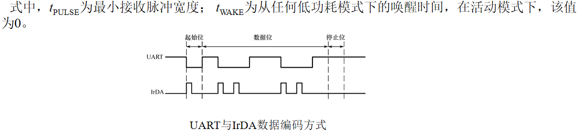
5. IrDA encoding and decoding
When the UCIREN control bit is set, the IrDA encoder and decoder will be enabled, and hardware coding and decoding will be provided for IrDA communication.
(1) IrDA code
On the basis of UART data stream, IrDA encoder will send a pulse to encode each bit 0 encountered in UART transmission. The coding method is shown in the figure, and the duration of the pulse is defined by UCIRTXPLx.
(2) IrDA decoding
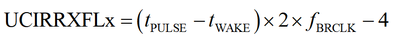
When UCIRRXPL=0, the decoder detects a high level, otherwise it detects a low level. In addition to the analog anti spike filter, USCI also contains a programmable digital filter, which can be enabled by the user by setting the UCIRRXFE control bit. When UCIRRXFE is set, only pulses exceeding the programmed filter length can pass through, and short pulses are discarded. The programming calculation formula of filter length UCIRRXFLx is as follows
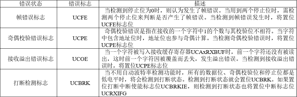
6. Automatic error detection
When the USCI module receives characters, it can automatically detect check errors, frame errors, overflow errors and interrupt states. When their respective states are detected, the corresponding interrupt flag bits UCFE, UCPE, UCOE and UCBRK are set. UCRXERR is also set when these error flags are in position. The meanings and marks of various errors are shown in the table.
7. USCI receive enable
The USCI module can be enabled by clearing the UCSWRST control bit. At this time, the receiving end is ready to receive data and is in the idle state, and the receiving baud rate generator is in the ready state, but no clock is generated.
The falling edge of the start bit enables the baud rate generator. The UART state machine can detect the valid start bit. If the valid start bit is not detected, the UART state machine returns to the idle state and stops the baud rate generator; If a valid start bit is detected, the character will be received.
When the line idle multi machine mode is selected (UCMODEx=01), the UART state machine detects the idle line after receiving a character. If a start bit is detected, the next character is received. Otherwise, if 10 1s are detected on the line, the UCIDLE idle flag bit will be set, the UART state machine returns to the idle state, and the baud rate generator is disabled.
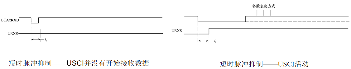
Suppressing the received data pulse interference can prevent the USCI module from accidentally starting. Any short-time pulse whose time on UCAxRXD is less than the anti spike pulse time tt (approximately 150ns) will be ignored by USCI and then initialized. As shown in the left figure, if the short-time pulse time on UCAxRXD is less than tt, USCI does not start receiving data.
When a spike pulse lasts longer than tt, or a valid start bit occurs on UCAxRXD, USCI starts receiving and adopts majority voting, as shown in the right figure. If the start bit is not detected by the majority vote, USCI stops receiving characters.
8. USCI send enable
The USCI module can be enabled by clearing the UCSWRST control bit. At this time, the transmitting end is ready to send data and is in the idle state, and the transmitting baud rate generator is in the ready state. However, no clock is generated.
USCI can start sending data by writing data to the send buffer register. The baud rate generator starts to work. When the transmission shift register is empty, the data in the transmission buffer register will be transferred to the transmission shift register on the next BITCLK.
After the previous byte is sent, the transmission can continue as long as there is new data in the transmission buffer register UCAxTXBUF. If no new data is written in the transmit buffer register UCAxTXBUF after the previous byte is sent, the transmitter will return to the idle state and stop the baud rate generator at the same time.
9. UART baud rate generation
USCI baud rate generator can generate standard baud rate from non-standard clock source frequency. Two operation modes provided by the system can be selected through UCOS16 control bit: generate low-frequency baud rate mode (UCOS16=0) and generate oversampled baud rate mode (UCOS16=1). The reference clock of UART baud rate comes from BRCLK, which can be configured as external clock UCAxCLK or internal clock ACLK or SMCLK through UCSSELx control bit.
(1) Generate low frequency baud rate mode
When UCOS16=0, select the low-frequency baud rate mode. This mode allows the generation of a standard baud rate from a low frequency clock source (e.g., 9600bps baud rate from a 32768Hz crystal oscillator). By using a lower input frequency, the power consumption of the system can be reduced. Note: under high frequency input or high frequency division setting, using this mode will lead to majority voting in a smaller window, which will reduce the advantages of majority voting.
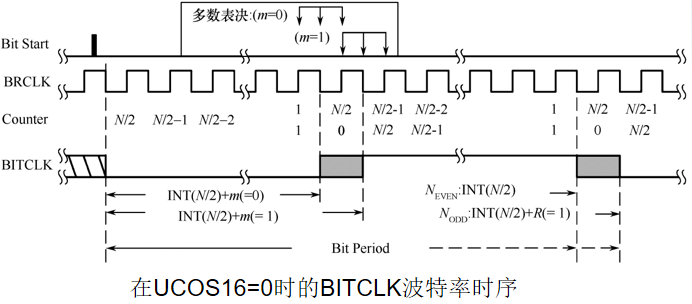
In low frequency mode, the baud rate generator uses a prescaler and a modulator to generate clock timing. In this combination, the generated baud rate supports fractional frequency division. In this mode, the maximum USCI baud rate is 1 / 3 of the UART source clock frequency BRCLK.
The timing of each bit is shown in the figure. For each received bit, in order to determine the value of this bit, the majority voting method, i.e. 2 out of 3 voting method, is adopted. Each vote is sampled 3 times, and the final value of this bit appears at least twice in the sampling. These samples occur at (N/2-1/2), N/2 and (N/2+1/2) BRCLK cycles, as shown in the box in the figure, where n is the value of BRCLKs contained in each BITCLK, and m in the figure is the modulation setting. See the following table for details.
(2) Generate oversampling baud rate mode
When UCOS16=1, select oversampling mode. This mode supports generating higher UART baud rate at higher input reference clock frequency. The reference clock of this mode is BITCLK16 clock generated by prescaler and modulator, and the clock frequency is 1 / 16 of BITCLK. Therefore, when calculating the frequency division coefficient, it is necessary to divide the reference clock frequency of the baud rate generator by 16 before calculation. For example, if the internal SMCLK=1048576Hz is selected for the reference clock BITCLK of the baud rate generator, it is finally necessary to generate a baud rate of 9600bps. First, divide BITCLK by 16 to 65536Hz as the baud rate reference clock in this mode, and calculate the frequency division coefficient as n=65536/9600=6.83.
This combination supports BITCLK16 and BITCLK to generate a baud rate that is not an integer multiple. In this case, the maximum USCI baud rate is 1 / 16 of the UART source clock frequency. When UCBRx is set to 0 or 1, the first stage frequency divider and modulator will be ignored, and BITCLK16 is equal to BITCLK. In this case, BITCLK16 has no modulation, so UCBRFx bit will be ignored.
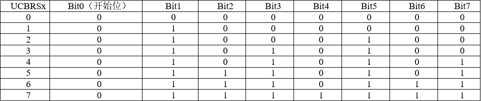
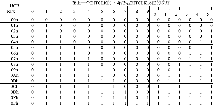
The modulation of BITCLK16 is based on the UCBRFx settings shown in the following table. 0 and 1 in the table represent the value of m. the period of BITCLK corresponding to m=1 is longer than that corresponding to m=0. Please refer to the modulation principle under the mode of generating low-frequency baud rate for the specific principle.
10. UART baud rate setting (important)
Setting method: when setting baud rate, first select the appropriate clock source. For lower baud rate (below 9600bps), ACLK can be selected as the clock source, which makes it possible to still use the serial port in LPM3 mode. Since there is a two out of three voting logic in the serial port receiving process, which requires at least 3 clock cycles, the frequency division coefficient must be greater than 3. Therefore, when the baud rate is higher than 9600bps, SMCLK with higher frequency should be selected as the clock source. In some special applications, external clock input can also be used as the clock source of baud rate generator.
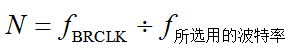
For a given BRCLK clock source, the baud rate used will determine the frequency division factor N, and the calculation formula is
The frequency division factor N is usually not an integer value, so at least one frequency divider and one modulator are required to approach the frequency division factor as close as possible. If N is equal to or greater than 16, the oversampling baud rate generation mode can be selected by setting UCOS16.
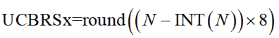
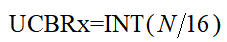
(1) Low frequency baud rate setting
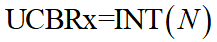
In the low frequency mode, the integer part of the frequency division factor is realized through the prescaler, and the configuration mode is (where INT is rounded)
The decimal part is realized by the modulator, and the configuration mode is (round is an integer nearby)
[example 1] in MSP430 single chip microcomputer, ACLK is used as the serial port clock source, and the baud rate is set to 4800bps.
Analysis: 4800bps baud rate is generated when ACLK=32768Hz, and the required frequency division coefficient is 32768 / 4800 = 6.83. The integer part is 6 and the decimal part is 0.83. Assign the integer part to the UCA0BR register, and the frequency division remainder of the modulator is 0.83 × 8 = 6.64, take the nearest integer 7, so assign 7 to the UCBRS control bit.
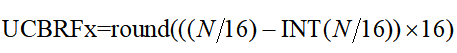
(2) Oversampling baud rate setting
In oversampling mode, prescaler is set to:
The modulator is set to:
[example 2] in MSP430 single chip microcomputer, SMCLK is used as the serial port clock source, and the baud rate is set to 9600bps.
Analysis: 9600bps baud rate is generated when SMCLK=1048576Hz, and the required frequency division coefficient N=1048576/ 9600=109.23 is greater than 16 frequency division. Therefore, the oversampling baud rate generation mode should be selected, and the pre frequency division UCBR should be set to INT(N/16)=INT(6.83)=6. The modulator UCBRF should be set to 0.83 × 16 = 13.28, take the nearest integer 13, so assign 13 to the UCBRF control bit.
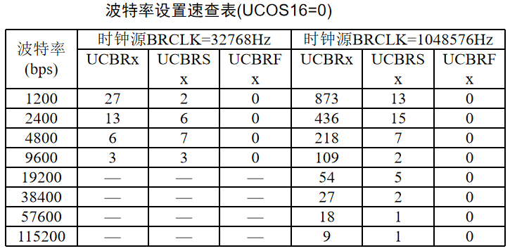
Baud rate setting can also be directly referred to the following table
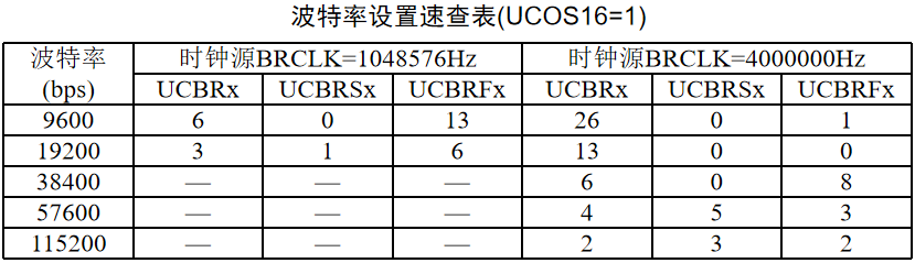
Or from MSP430 USCI/EUSCI UART Baud Rate Calculation Get in
UART API (mechanical turnover)
USCI_A_UART API is divided into several groups of functions:
USCI_ A_ Functions of UART module configuration and control,
Functions for sending and receiving data,
And functions to handle interrupt processing and DMA processing.
USCI_A_UART configuration and control functions:
USCI_A_UART_init(uint16_t baseAddress, USCI_A_UART_initParam ∗param)
//Initialization function
USCI_A_UART_enable(uint16_t baseAddress)
//Enable UART module
USCI_A_UART_disable(uint16_t baseAddress)
//Disabled UART module
USCI_A_UART_setDormant(uint16_t baseAddress)
//Set the UART module to sleep mode
USCI_A_UART_resetDormant(uint16_t baseAddress)
//Re enable the UART module from sleep mode
USCI_A_UART_initParam structure
typedef struct USCI_A_UART_initParam {
    //! Selects Clock source.
    //! \n Valid values are:
    //! - \b USCI_A_UART_CLOCKSOURCE_SMCLK
    //! - \b USCI_A_UART_CLOCKSOURCE_ACLK
    uint8_t selectClockSource;
    //! Is the value to be written into UCBRx bits
    uint16_t clockPrescalar;
    //! Is First modulation stage register setting. This value is a pre-
    //! calculated value which can be obtained from the Device Users Guide.
    //! This value is written into UCBRFx bits of UCAxMCTLW.
    uint8_t firstModReg;
    //! Is Second modulation stage register setting. This value is a pre-
    //! calculated value which can be obtained from the Device Users Guide.
    //! This value is written into UCBRSx bits of UCAxMCTLW.
    uint8_t secondModReg;
    //! Is the desired parity.
    //! \n Valid values are:
    //! - \b USCI_A_UART_NO_PARITY [Default]
    //! - \b USCI_A_UART_ODD_PARITY
    //! - \b USCI_A_UART_EVEN_PARITY
    uint8_t parity;
    //! Controls direction of receive and transmit shift register.
    //! \n Valid values are:
    //! - \b USCI_A_UART_MSB_FIRST
    //! - \b USCI_A_UART_LSB_FIRST [Default]
    uint8_t msborLsbFirst;
    //! Indicates one/two STOP bits
    //! \n Valid values are:
    //! - \b USCI_A_UART_ONE_STOP_BIT [Default]
    //! - \b USCI_A_UART_TWO_STOP_BITS
    uint8_t numberofStopBits;
    //! Selects the mode of operation
    //! \n Valid values are:
    //! - \b USCI_A_UART_MODE [Default]
    //! - \b USCI_A_UART_IDLE_LINE_MULTI_PROCESSOR_MODE
    //! - \b USCI_A_UART_ADDRESS_BIT_MULTI_PROCESSOR_MODE
    //! - \b USCI_A_UART_AUTOMATIC_BAUDRATE_DETECTION_MODE
    uint8_t uartMode;
    //! Indicates low frequency or oversampling baud generation
    //! \n Valid values are:
    //! - \b USCI_A_UART_OVERSAMPLING_BAUDRATE_GENERATION
    //! - \b USCI_A_UART_LOW_FREQUENCY_BAUDRATE_GENERATION
    uint8_t overSampling;
} USCI_A_UART_initParam;
Among them, clockPrescalar, firstModReg, secondModReg and overSampling
Available in MSP430 USCI/EUSCI UART Baud Rate Calculation Get in
Functions for sending and receiving data
USCI_A_UART_transmitData(uint16_t baseAddress, uint8_t transmitData)
//One byte is transmitted through UART module
USCI_A_UART_receiveData(uint16_t baseAddress)
//Receive a byte that has been sent to the UART module.
USCI_A_UART_transmitAddress(uint16_t baseAddress, uint8_t transmitAddress)
//Transmits the next byte to be transmitted marked as address depending on selected multiprocessor mode
USCI_A_UART_transmitBreak(uint16_t baseAddress)
//Transmission interruption
Manage USCI_A_UART interrupt and status
USCI_A_UART_enableInterrupt(uint16_t baseAddress, uint8_t mask)
//Enable UART interrupt
USCI_A_UART_disableInterrupt(uint16_t baseAddress, uint8_t mask)
//Disable UART interrupt
USCI_A_UART_getInterruptStatus(uint16_t baseAddress, uint8_t mask)
//Gets the current UART interrupt status. This will return the interrupt status of the UART module according to the passed flag
USCI_A_UART_clearInterrupt(uint16_t baseAddress, uint8_t mask)
//Clear the UART interrupt source so that it is no longer asserted. When using the interrupt vector generator, the highest interrupt flag is automatically cleared
USCI_A_UART_queryStatusFlags(uint16_t baseAddress, uint8_t mask)
//Gets the current UART status flag. This will return the status of the UART module according to the passed flag.
DMA related
USCI_A_UART_getReceiveBufferAddressForDMA(uint16_t baseAddress)
//Return RX buffer address of UART DMA module
USCI_A_UART_getTransmitBufferAddressForDMA(uint16_t baseAddress)
//Returns the TX buffer address of UART DMA module
Write UART initialization function through DriverLib library and hardware knowledge
According to the previous knowledge, we can write the following initialization function
The parameter of baseAddress is optional
USCI_A0_BASE,USCI_A1_BASE,
Corresponding to P3 3,P3.4 and P4 4,P4. five
Baudrate is the target baud rate
bool UART_Init(uint16_t baseAddress, uint32_t Baudrate)
{
    float UART_Temp = 0;
    USCI_A_UART_initParam huart = {0};
	//Multiplex the used pins to UART mode
    if(baseAddress == USCI_A0_BASE)         //P3.3, P3.4 = USCI_A0 TXD/RXD
    {
        GPIO_setAsPeripheralModuleFunctionOutputPin(GPIO_PORT_P3, GPIO_PIN3);
        GPIO_setAsPeripheralModuleFunctionInputPin(GPIO_PORT_P3, GPIO_PIN4);
    }
    else if(baseAddress == USCI_A1_BASE)    //P4.4, P4.5 = USCI_A1 TXD/RXD
    {
        GPIO_setAsPeripheralModuleFunctionOutputPin(GPIO_PORT_P4, GPIO_PIN4);
        GPIO_setAsPeripheralModuleFunctionInputPin(GPIO_PORT_P4, GPIO_PIN5);
    }
	//When the target baud rate is low, the UART selects the clock source as ACLK, and vice versa, selects SMCLK
	//Call UCS_ getACLK/UCS_ Call UCS correctly before getsmclk_ Setexternalclocksource function, which I have added to systemclock_ In init function
    if(Baudrate <= 9600)
    {
        huart.selectClockSource = USCI_A_UART_CLOCKSOURCE_ACLK;
        UART_Temp = (float)UCS_getACLK()/Baudrate;
    }
    else
    {
        huart.selectClockSource = USCI_A_UART_CLOCKSOURCE_SMCLK;
        UART_Temp = (float)UCS_getSMCLK()/Baudrate;
    }

    if(UART_Temp < 16)	//When the frequency division factor is less than 16, the low-frequency baud rate setting is adopted
        huart.overSampling = USCI_A_UART_LOW_FREQUENCY_BAUDRATE_GENERATION;
    else	//Conversely, the oversampling baud rate setting is used
    {
        huart.overSampling = USCI_A_UART_OVERSAMPLING_BAUDRATE_GENERATION;
        UART_Temp /= 16;
    }

    huart.clockPrescalar = (int)UART_Temp;

    if(huart.overSampling == USCI_A_UART_LOW_FREQUENCY_BAUDRATE_GENERATION)
    {	//Low frequency baud rate setting 	 UCBRSx
        huart.secondModReg = (int)((UART_Temp - huart.clockPrescalar) * 8);
    }
    else
    {	//Oversampling baud rate setting UCBRFx
        huart.firstModReg = (int)((UART_Temp - huart.clockPrescalar) * 16);
    }

    huart.parity = USCI_A_UART_NO_PARITY;
    huart.msborLsbFirst = USCI_A_UART_LSB_FIRST;
    huart.numberofStopBits = USCI_A_UART_ONE_STOP_BIT;
    huart.uartMode = USCI_A_UART_MODE;

    if (STATUS_FAIL == USCI_A_UART_init(baseAddress, &huart))
    {	//Initialize corresponding serial port
        return STATUS_FAIL;
    }

    //Enable UART module for operation enables the corresponding serial port
    USCI_A_UART_enable(baseAddress);

    //Enable Receive Interrupt enable serial port interrupt
    USCI_A_UART_clearInterrupt(baseAddress, USCI_A_UART_RECEIVE_INTERRUPT);
    USCI_A_UART_enableInterrupt(baseAddress, USCI_A_UART_RECEIVE_INTERRUPT);

    return STATUS_SUCCESS;
}
The serial port interrupt service function sends back one character after receiving one character
//******************************************************************************
//
//This is the USCI_A0 interrupt vector service routine.
//
//******************************************************************************
#pragma vector=USCI_A0_VECTOR
__interrupt void USCI_A0_ISR (void)
{
    uint8_t receivedData = 0;
    switch (__even_in_range(UCA0IV,4))
    {
        //Vector 2 - RXIFG
        case 2:
            receivedData = USCI_A_UART_receiveData(USCI_A0_BASE);
            USCI_A_UART_transmitData(USCI_A0_BASE,receivedData);
            break;
        default:
            break;
    }
}

//******************************************************************************
//
//This is the USCI_A1 interrupt vector service routine.
//
//******************************************************************************
#pragma vector=USCI_A1_VECTOR
__interrupt void USCI_A1_ISR (void)
{
    uint8_t receivedData = 0;
    switch (__even_in_range(UCA1IV,4))
    {
        //Vector 2 - RXIFG
        case 2:
            receivedData = USCI_A_UART_receiveData(USCI_A1_BASE);
            USCI_A_UART_transmitData(USCI_A1_BASE,receivedData);
            break;
        default:
            break;
    }
}
Serial port part of schematic diagram
USCI_A0 UART corresponds to P3 3,P3. four
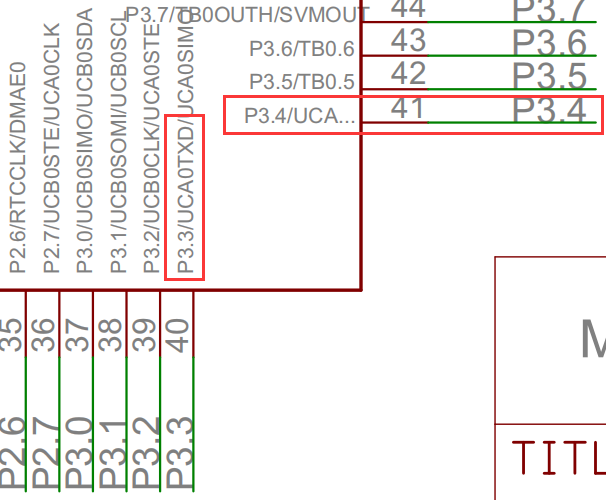
USCI_A1 UART corresponds to P4 4,P4. five
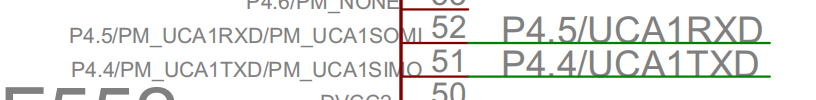
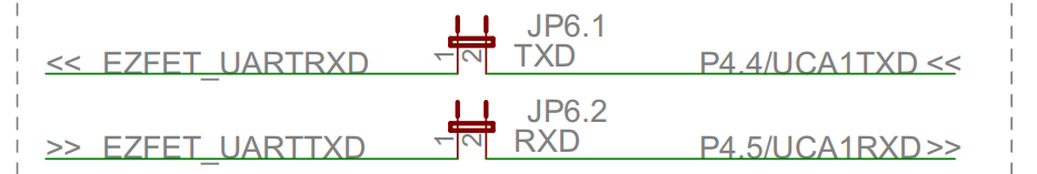
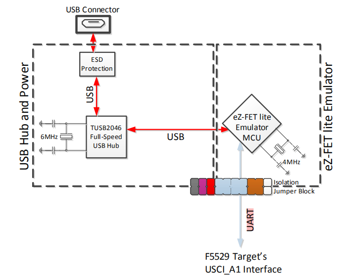
As shown in the figure, the usci of MSP430F5529_ A1 UART communicates with USB through EZ FET
In other words, the serial port recognized after inserting microUSB should be USCI_A1 UART
Actual combat
The entire source file is as follows
#include "driverlib.h"
#define MCLK_IN_HZ 25000000
#define delay_us(x) __delay_cycles((MCLK_IN_HZ/1000000*(x)))
#define delay_ms(x) __delay_cycles((MCLK_IN_HZ/1000*(x)))
void SystemClock_Init(void)
{
PMM_setVCore(PMM_CORE_LEVEL_3); //High dominant frequency operation requires high core voltage
//XT1 pin multiplexing
GPIO_setAsPeripheralModuleFunctionInputPin(GPIO_PORT_P5, GPIO_PIN4);
GPIO_setAsPeripheralModuleFunctionOutputPin(GPIO_PORT_P5, GPIO_PIN5);
//Starting vibration XT1
UCS_turnOnLFXT1(UCS_XT1_DRIVE_3,UCS_XCAP_3);
//XT2 pin multiplexing
GPIO_setAsPeripheralModuleFunctionInputPin(GPIO_PORT_P5, GPIO_PIN2);
GPIO_setAsPeripheralModuleFunctionOutputPin(GPIO_PORT_P5, GPIO_PIN3);
//Starting vibration XT2
UCS_turnOnXT2(UCS_XT2_DRIVE_4MHZ_8MHZ);
//XT2 is used as FLL reference clock, first 8 frequency division, then 50 frequency multiplication 4MHz / 8 * 50 = 25MHz
UCS_initClockSignal(UCS_FLLREF, UCS_XT2CLK_SELECT, UCS_CLOCK_DIVIDER_8);
UCS_initFLLSettle(25000, 50);
//XT1 as ACLK clock source = 32768Hz
UCS_initClockSignal(UCS_ACLK, UCS_XT1CLK_SELECT, UCS_CLOCK_DIVIDER_1);
//DCOCLK as MCLK clock source = 25MHz
UCS_initClockSignal(UCS_MCLK, UCS_DCOCLK_SELECT, UCS_CLOCK_DIVIDER_1);
//DCOCLK as SMCLK clock source = 25MHz
UCS_initClockSignal(UCS_SMCLK, UCS_DCOCLK_SELECT, UCS_CLOCK_DIVIDER_1);
//Set the frequency of the external clock source so that when calling UCS_getMCLK, UCS_getSMCLK or UCS_ The correct value can be obtained when getaclk
UCS_setExternalClockSource(32768, 4000000);
}
bool UART_Init(uint16_t baseAddress, uint32_t Baudrate)
{
float UART_Temp = 0;
USCI_A_UART_initParam huart = {0};
if(baseAddress == USCI_A0_BASE) //P3.3, P3.4 = USCI_A0 TXD/RXD
{
GPIO_setAsPeripheralModuleFunctionOutputPin(GPIO_PORT_P3, GPIO_PIN3);
GPIO_setAsPeripheralModuleFunctionInputPin(GPIO_PORT_P3, GPIO_PIN4);
}
else if(baseAddress == USCI_A1_BASE) //P4.4, P4.5 = USCI_A1 TXD/RXD
{
GPIO_setAsPeripheralModuleFunctionOutputPin(GPIO_PORT_P4, GPIO_PIN4);
GPIO_setAsPeripheralModuleFunctionInputPin(GPIO_PORT_P4, GPIO_PIN5);
}
if(Baudrate <= 9600)
{
huart.selectClockSource = USCI_A_UART_CLOCKSOURCE_ACLK;
UART_Temp = (float)UCS_getACLK()/Baudrate;
}
else
{
huart.selectClockSource = USCI_A_UART_CLOCKSOURCE_SMCLK;
UART_Temp = (float)UCS_getSMCLK()/Baudrate;
}
if(UART_Temp < 16)
huart.overSampling = USCI_A_UART_LOW_FREQUENCY_BAUDRATE_GENERATION;
else
{
huart.overSampling = USCI_A_UART_OVERSAMPLING_BAUDRATE_GENERATION;
UART_Temp /= 16;
}
huart.clockPrescalar = (int)UART_Temp;
if(huart.overSampling == USCI_A_UART_LOW_FREQUENCY_BAUDRATE_GENERATION)
{
huart.secondModReg = (int)((UART_Temp - huart.clockPrescalar) * 8);
}
else
{
huart.firstModReg = (int)((UART_Temp - huart.clockPrescalar) * 16);
}
huart.parity = USCI_A_UART_NO_PARITY;
huart.msborLsbFirst = USCI_A_UART_LSB_FIRST;
huart.numberofStopBits = USCI_A_UART_ONE_STOP_BIT;
huart.uartMode = USCI_A_UART_MODE;
if (STATUS_FAIL == USCI_A_UART_init(baseAddress, &huart))
{
return STATUS_FAIL;
}
//Enable UART module for operation
USCI_A_UART_enable(baseAddress);
//Enable Receive Interrupt
USCI_A_UART_clearInterrupt(baseAddress, USCI_A_UART_RECEIVE_INTERRUPT);
USCI_A_UART_enableInterrupt(baseAddress, USCI_A_UART_RECEIVE_INTERRUPT);
return STATUS_SUCCESS;
}
int main(void)
{
WDT_A_hold(WDT_A_BASE);
SystemClock_Init();
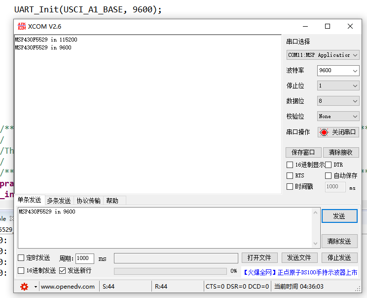
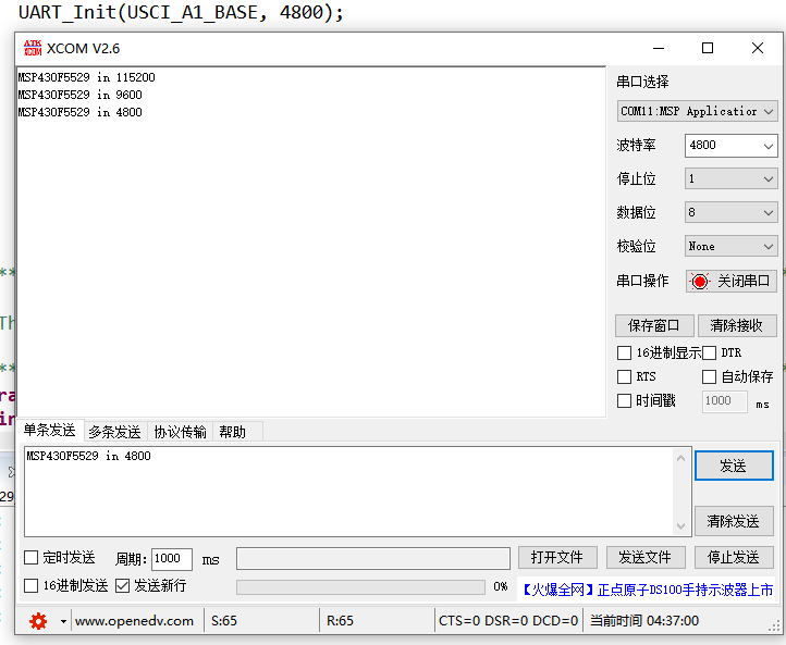
UART_Init(USCI_A1_BASE, 115200);
//interrupts enabled
__bis_SR_register(GIE);
while(1)
{
}
}
//******************************************************************************
//
//This is the USCI_A0 interrupt vector service routine.
//
//******************************************************************************
#pragma vector=USCI_A0_VECTOR
__interrupt void USCI_A0_ISR (void)
{
uint8_t receivedData = 0;
switch (__even_in_range(UCA0IV,4))
{
//Vector 2 - RXIFG
case 2:
receivedData = USCI_A_UART_receiveData(USCI_A0_BASE);
USCI_A_UART_transmitData(USCI_A0_BASE,receivedData);
break;
default:
break;
}
}
//******************************************************************************
//
//This is the USCI_A1 interrupt vector service routine.
//
//******************************************************************************
#pragma vector=USCI_A1_VECTOR
__interrupt void USCI_A1_ISR (void)
{
uint8_t receivedData = 0;
switch (__even_in_range(UCA1IV,4))
{
//Vector 2 - RXIFG
case 2:
receivedData = USCI_A_UART_receiveData(USCI_A1_BASE);
USCI_A_UART_transmitData(USCI_A1_BASE,receivedData);
break;
default:
break;
}
}
In the main function, the
UART_Init(USCI_A1_BASE, 115200);
Initialize the serial port we use
Connect the serial port debugging assistant and echo successfully
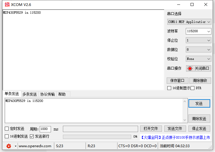
If the baud rate is modified, the communication can still succeed