(1) MSP432 serial port introduction
MSP432P401R does not have a special serial port device. To use the EUSC module to configure UART mode, serial port communication is very convenient and easy to use. It is the most common interface in embedded devices. Here, we configure the serial port of MSP432 to 8in1 mode, 8-bit data, 1-bit stop bit, no flow control selection, 9600 baud rate, and direct transmission, The reception mode is interrupt reception.

It should be noted that only EUSCA support is configured to serial port mode.
(2) Configure serial port
first open the serial port call back routine of TI, then configure it according to it, and then test it:
(1) Initialize serial port
It should be noted that SMCLK is selected for the serial port clock. In the previous example, SMCLK has been configured to 12MHz, so we need to obtain the frequency division number of specific baud rate, etc. here, TI gives a table in the man Manual:
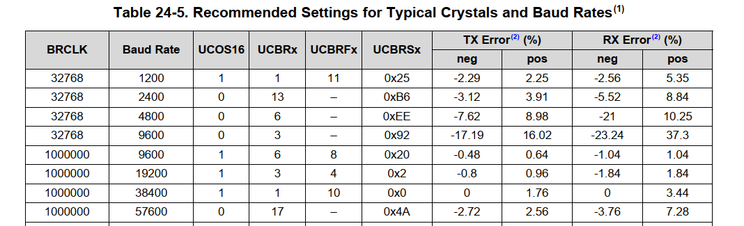
The detailed parameter configuration is given in this table. Find 12000000, and then find that it needs to be configured like this:

Then the parameters to be configured are ucbrx, ucbrfx and bcbrsx. The three values here correspond to the first three of the configuration information respectively. The serial port with 9600 baud rate 8In1 is configured according to 12MHz SMCLK as follows:
//initialization
const eUSCI_UART_ConfigV1 uartConfig =
{
        EUSCI_A_UART_CLOCKSOURCE_SMCLK,          // SMCLK Clock Source = 12MHz
        78,                                      // BRDIV = 78
        2,                                       // UCxBRF = 2
        0,                                       // UCxBRS = 0
        EUSCI_A_UART_NO_PARITY,                  // No Parity
        EUSCI_A_UART_LSB_FIRST,                  // LSB First
        EUSCI_A_UART_ONE_STOP_BIT,               // One stop bit
        EUSCI_A_UART_MODE,                       // UART mode
        EUSCI_A_UART_OVERSAMPLING_BAUDRATE_GENERATION,  // Oversampling
        EUSCI_A_UART_8_BIT_LEN                   // 8 bit data length
};


/**
 * @editior: zyg
 * @brief  : none
 * @param  : none
 * @return : NULL
 * @example: void ANO_DT_Init(void)
 */
void ANO_DT_Init(void)
{
	/* Selecting P1.2 and P1.3 in UART mode and P1.0 as output (LED) */
    GPIO_setAsPeripheralModuleFunctionInputPin(GPIO_PORT_P3,
             GPIO_PIN2 | GPIO_PIN3, GPIO_PRIMARY_MODULE_FUNCTION);

    /* Configuring UART Module */
    UART_initModule(EUSCI_A2_BASE, &uartConfig);

	/* Enable UART module */
    UART_enableModule(EUSCI_A2_BASE);

	/* Enable Interrupt */
	UART_enableInterrupt(EUSCI_A2_BASE,EUSCI_A_UART_RECEIVE_INTERRUPT);
    Interrupt_enableInterrupt(INT_EUSCIA2);
}
(2) Interrupt function configuration
/* Serial port interrupt function */
void EUSCIA2_IRQHandler(void)
{
	uint8 datA2 = 0;
	//read
	datA2 = UART_receiveData(EUSCI_A2_BASE);;
	ps2gamepad_decode(datA2,&PS2);
	UART_clearInterruptFlag(EUSCI_A2_BASE,EUSCI_A_UART_RECEIVE_INTERRUPT);
}
(3) Test function
Here, the PS2 handle is transferred to the serial port for test reception and transmission. Just conduct the reception test directly. There is no problem with reception and generally no problem with transmission:
/* ps2 Handle decoding program */
void ps2gamepad_decode(uint8 dat,ps2datatypedef *p)
{
	/* Rocker reception mode */
	//if(p->l_rocker == 0 && )
	/* Non rocker reception mode */
	if(dat == 'A')
		p->l_up = 1;
	else if(dat == 'B')
		p->l_down = 1;
	else if(dat == 'C')
		p->l_left = 1;
	else if(dat == 'D')
		p->l_right = 1;
}
Due to the special sending process of PS2 to serial port module, all marks have to be cleared once in 300ms to solve the problem of mark change. Finally, the reception is normal. Use 432 to send vibration information to the handle room, the handle can vibrate normally, and the serial port communication is successful.
(3) Law summary
For an embedded processor, the most commonly used and simplest module is the serial port, which is often used for debugging in linux. For debugging the serial port, we first need to know the clock source of the serial port, then configure the frequency division coefficient and configure the function register to use the serial port. If interrupt reception is used, we also need to turn on the serial port interrupt and turn on the total interrupt, Then, after the interrupt is completed, the flag bit needs to be cleared to prevent the interrupt from being executed only once or not. These are basically the development process of serial port.