
NAT address translation overview
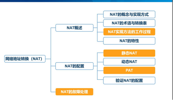
In this chapter, we will learn and practice static NAT address translation, dynamic NAT address translation.
Port mapping, PAT port multiplexing
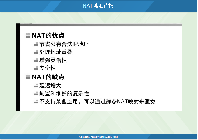
I. understand the advantages and disadvantages of NAT
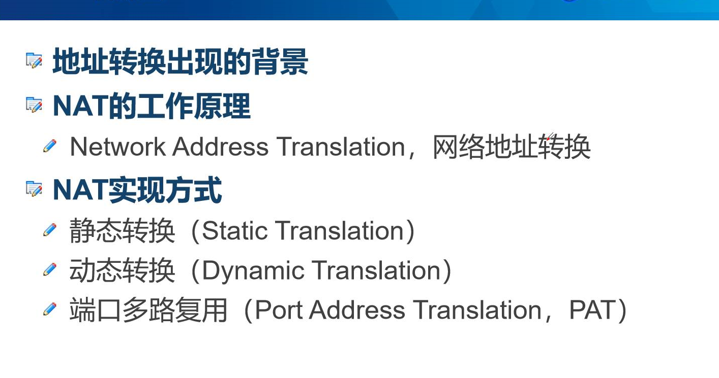
II. Operation principle of NAT
Static translation
Dynamic Translation
Port Address Translation
III. terminology of NAT in conversion table
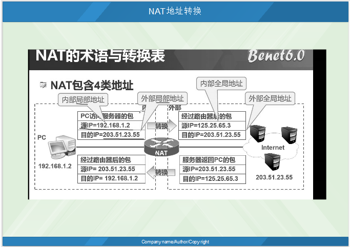
A camouflage of NAT address translation ensures the security of address
 As shown in the picture:
The first thing PC1 requests is to query the routing table first, and then convert it into a public network address according to the NAT table to access the external network. Source IP, destination IP. At this time, the external source IP becomes the public network address.
PC2 responds to the first thing, first query the NAT conversion table, and then query the routing table to send packets.
In response, if two interfaces query the routing table first, they cannot find it. One interface is 1.0 and the other is 125.0.

Internal:
Source IP: internal local address
 Destination IP: external local address
 External:
Source IP: internal global address
 Destination IP: external global address
IV. conversion entry of NAT

Simple conversion entry according to IP
 Expansion conversion entry based on IP and port
V. working process of NAT
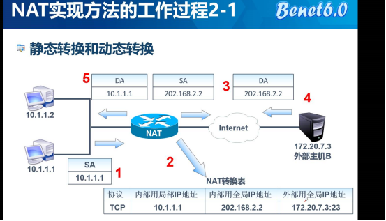
1: address of own host 10.1.1.1
 2. According to the NAT conversion table, you need to manually configure the TCP protocol. Local IP address is used internally, global IP address is used internally and global IP address is used externally.
3. Destination IP address
 4. Access to external network
 5. Destination IP address and source IP address
Vi. working process of PAT

PAT is the conversion of multiple private network addresses into one public network address. With more ports, the ports can be set by themselves.
***Both ends of the tunnel are fixed IP addresses, so the translation address changes.
There's a technology that goes through technology, around it.
7. Static NAT address experiment diagram
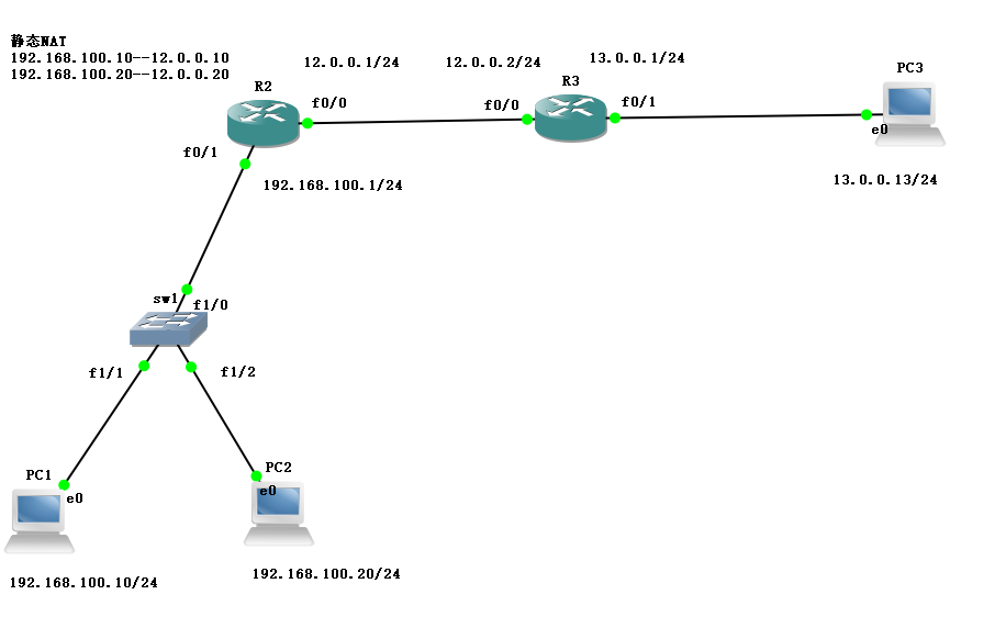
sw1:Turn off routing, set rate and full duplex
R3:Interface matching IP,Configure default route
f0/0:12.0.0.2/24
f0/1:13.0.0.1/24
R2:Interface matching IP,Configure default route back, configure static NAT Address translation, applying to interfaces
f0/0:12.0.0.1/24
f0/1:192.168.100.1/24
PC1:192.168.100.10/24
PC2:192.168.100.20/24
7.1. Configure the switch with speed, full duplex, and turn off the routing function
sw1#conf t
sw1(config)#no ip routing / / turn off routing.
sw1(config)#int f1/0
sw1(config-if)#speed 100 / / rate 100
sw1(config-if)#dup full / / full duplex mode
sw1(config-if)#ex
7.2 configure d address and default route for R3 interface of router
R3#conf t
R3(config)#int f0/0
R3(config-if)#ip add 12.0.0.2 255.255.255.0 / / configure the address
R3(config-if)#no shut / / enable the address interface
R3(config-if)#int f0/1
R3(config-if)#ip add 13.0.0.1 255.255.255.0
R3(config-if)#no shut
R3(config-if)#do show ip route / / view the route table entries
Codes: C - connected, S - static, R - RIP, M - mobile, B - BGP
       D - EIGRP, EX - EIGRP external, O - OSPF, IA - OSPF inter area
       N1 - OSPF NSSA external type 1, N2 - OSPF NSSA external type 2
       E1 - OSPF external type 1, E2 - OSPF external type 2
       i - IS-IS, su - IS-IS summary, L1 - IS-IS level-1, L2 - IS-IS level-2
       ia - IS-IS inter area, * - candidate default, U - per-user static route
       o - ODR, P - periodic downloaded static route

Gateway of last resort is not set

     12.0.0.0/24 is subnetted, 1 subnets
C       12.0.0.0 is directly connected, FastEthernet0/0
     13.0.0.0/24 is subnetted, 1 subnets
C       13.0.0.0 is directly connected, FastEthernet0/1
R3(config-if)#ex
R3(config)#IP route 0.0.0.0.0.0.0.0 12.0.0.1 / / configure the default route
R3(config)#
7.3 assign IP to R2 interface and configure default route back
R2#conf t
R2(config)#int f0/0
R2(config-if)#ip add 192.168.100.1 255.255.255.0 / / configure the address
R2(config-if)#no shut
R2(config-if)#int f0/1
R2(config-if)#ip add 12.0.0.1 255.255.255.0 / / configure the address
R2(config-if)#no shut
R2(config-if)#ex
R2(config)#ip route 0.0.0.0 0.0.0.0 12.0.0.2
R2(config)#
7.4 configure address for each host
PC1> ip 192.168.100.10 192.168.100.1
Checking for duplicate address...
PC1 : 192.168.100.10 255.255.255.0 gateway 192.168.100.1

PC2> ip 192.168.100.20 192.168.100.1
Checking for duplicate address...
PC1 : 192.168.100.20 255.255.255.0 gateway 192.168.100.1

PC3> ip 13.0.0.13 13.0.0.1
Checking for duplicate address...
PC1 : 13.0.0.13 255.255.255.0 gateway 13.0.0.1
7.5 configure R2 with static NAT address translation and apply it to the interface
R2#conf t
R2(config)#ip nat inside source static 192.168.100.10 12.0.0.10
//Set static NAT address intranet to extranet
R2(config)#ip nat inside source static 192.168.100.20 12.0.0.20
R2(config)#int f0/0
R2(config-if)#ip nat inside / / set the F0/0 interface to internal.
R2(config-if)#int f0/1
R2(config-if)#ip nat outside / / set the external interface to F0/1
R2(config-if)#end
R2#debug ip nat / / check the NAT address translation status.
IP NAT debugging is on
VIII. Static NAT mapping
NAT Port Mapping Protocol (NAT-PMP) is a network protocol that can automatically create network address translation (NAT) settings and port mapping configurations without user intervention. The protocol can automatically determine the external IPv4 address of NAT gateway and provide a method for application to communicate with peers. NAT-PMP, introduced by apple in 2005, is an alternative to the more common ISO standard Internet gateway device protocol implemented by many NAT routers. The protocol was published by Internet Engineering Task Force (IETF) in RFC 6886. NAT-PMP uses user datagram protocol (UDP) to run on port 5351. There is no built-in authentication mechanism in this protocol, because forwarding a port usually does not allow any activity, nor can it be implemented by STUN method. The advantage of NAT-PMP compared with STUN is that it does not need STUN server, and NAT-PMP mapping has a known expiration time, so applications can avoid inefficient sending of live packets. NAT-PMP is the predecessor of port control protocol (PCP).
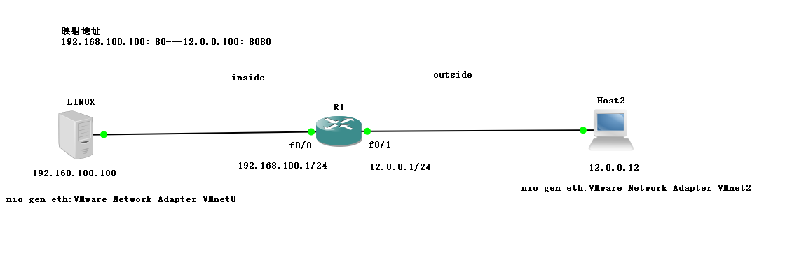
8.1 experimental plots
If you want to access the private network address on the WAN, you must have a mapped address
The purpose of the experiment is to let the host of the external network access the WEB service of linux.
8.2 install HTTPD service in linux server and write a web page for self-test
[root @ localhost ~] (Yum install HTTPD - Y / / install the HTTPD service.
[root @ localhost ~] (VIM / var / www / HTML / index. HTML / / create files and content on behalf of the site.
<h1>this is web NAT </h1>
~
[root @ localhost ~] (systemctl start HTTPD / / start HTTPD service
[root @ localhost ~] (systemctl stop firewalld. Service / / close the firewall
[root @ localhost ~] (setenforce 0 / / enable the enhancement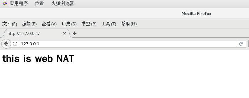
8.3 Linux server binds network card and sets fixed IP
[root@localhost ~]# vim /etc/sysconfig/network-scripts/ifcfg-ens33
TYPE=Ethernet
PROXY_METHOD=none
BROWSER_ONLY=no
BOOTPROTO=static  //Set static
DEFROUTE=yes
IPV4_FAILURE_FATAL=no
IPV6INIT=yes
IPV6_AUTOCONF=yes
IPV6_DEFROUTE=yes
IPV6_FAILURE_FATAL=no
IPV6_ADDR_GEN_MODE=stable-privacy
NAME=ens33
UUID=849aa04e-1874-490f-8cb0-b2fde4b9a6f8
DEVICE=ens33
ONBOOT=yes
IPADDR=192.168.100.100   //IP address
NETMASK=255.255.255.0   //Subnet mask
GATEWAY=192.168.100.1   //gateway
[root@localhost ~]# systemctl restart network / / restart the network service
[root@localhost ~]# ifconfig
ens33: flags=4163<UP,BROADCAST,RUNNING,MULTICAST>  mtu 1500
        inet 192.168.100.100  netmask 255.255.255.0  broadcast 192.168.100.255
        inet6 fe80::e3c7:14af:6e4d:7216  prefixlen 64  scopeid 0x20<link>
        ether 00:0c:29:c9:dd:05  txqueuelen 1000  (Ethernet)
        RX packets 4309  bytes 4579244 (4.3 MiB)
        RX errors 0  dropped 0  overruns 0  frame 0
        TX packets 1123  bytes 96283 (94.0 KiB)
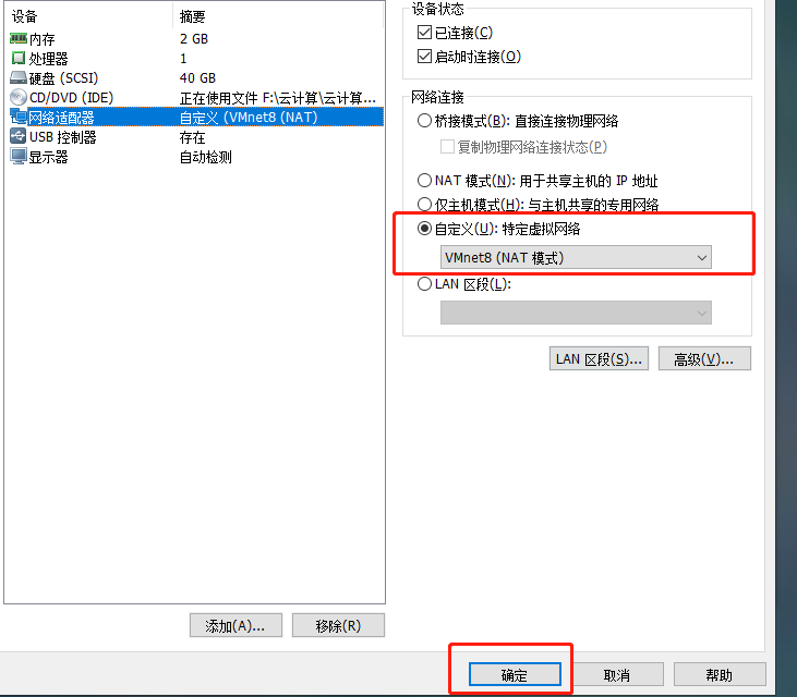
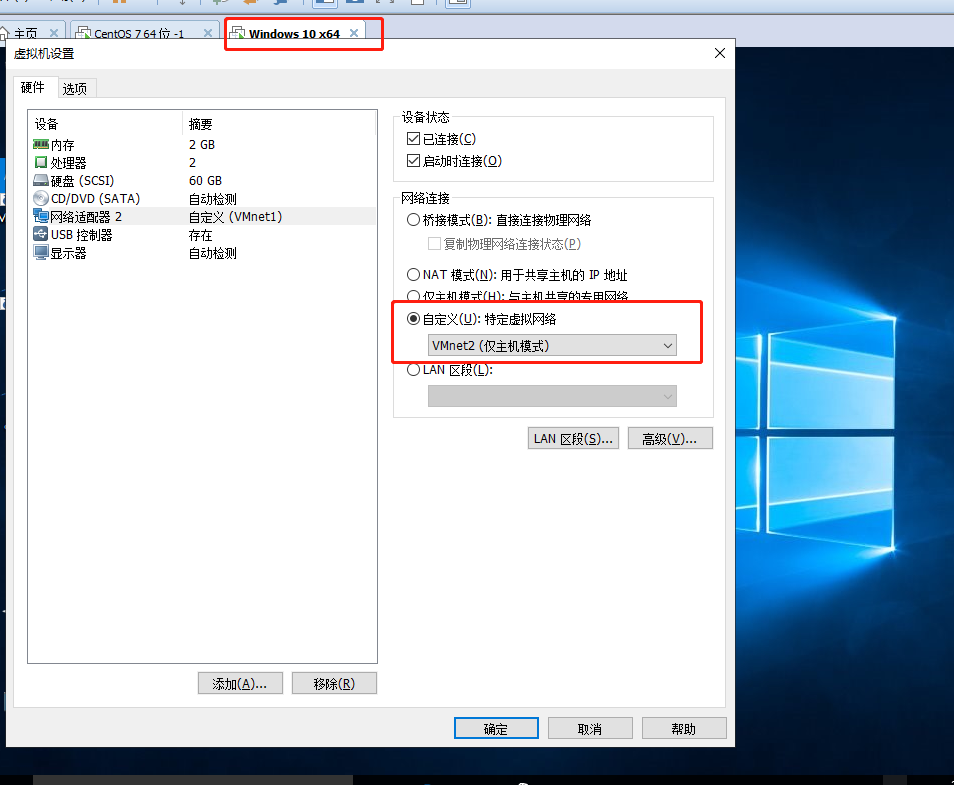
8.4 bind network card to win10
8.5 configure R1 router to GNS3 and address the interface
R1#conf t
R1(config)#int f0/0
R1(config-if)#ip add 192.168.100.1 255.255.255.0
R1(config-if)#no shut
R1(config-if)#int f0/1
R1(config-if)#ip add 12.0.0.1 255.255.255.0
R1(config-if)#no shut
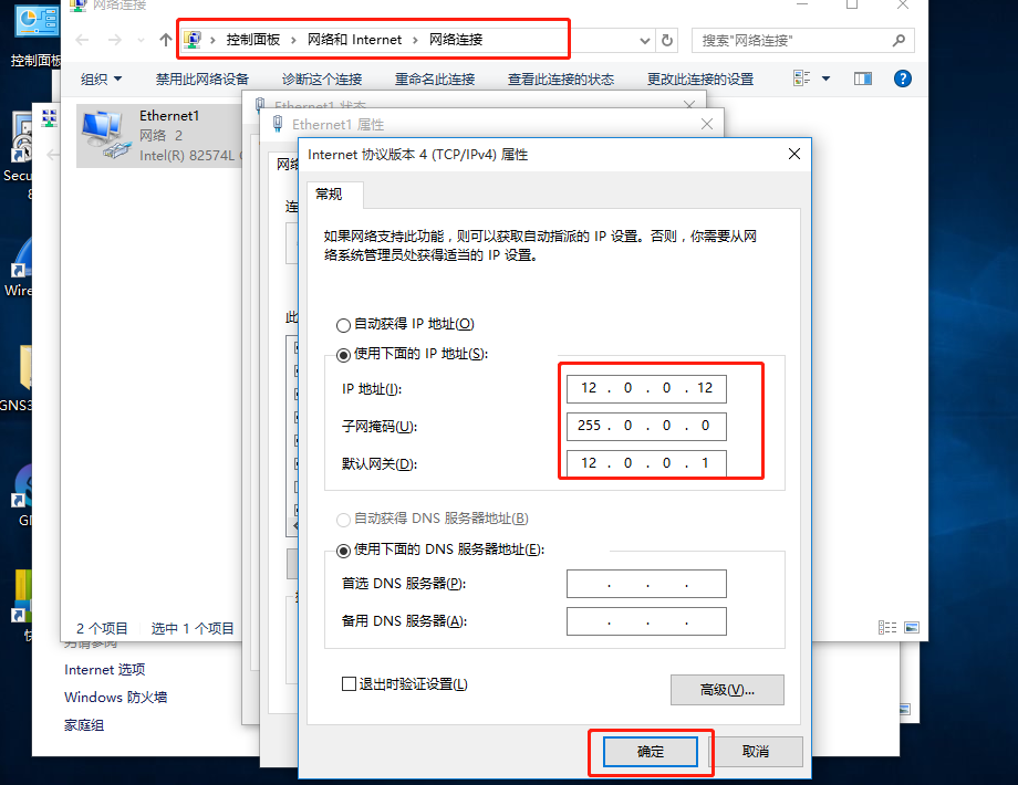
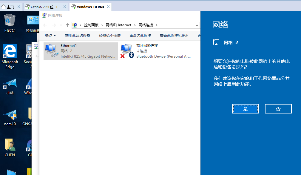
8.6 return to WIN10 setting address
8.7 go back to GNS3 and start to configure port mapping
What does mapping mean? That is, if the external network wants to access your private network address, it must be mapped, otherwise it is not safe.
R1#conf t
R1(config)#ip nat inside source static tcp 192.168.100.100 80 12.0.0.100 8080 extendable
 //Internal port enables NAT,tcp protocol, IP address plus port, maps external network address plus port, and must be followed by an extension
 on Interface NVI0, changed state to up
R1(config)#int f0/0
R1(config-if)#ip nat inside / / set to internal
R1(config-if)#int f0/1
R1(config-if)#ip nat outside / / set to external
R1(config-if)#end
R1#debug ip nat / / test to start port mapping
IP NAT debugging is on
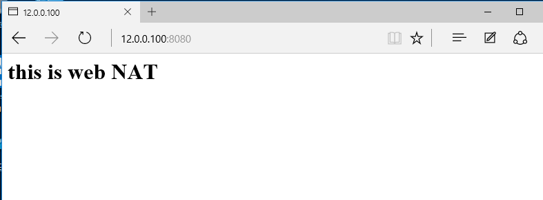
8.8 let's go back to a host in the external network to visit
http://12.0.0.100:8080/ Be sure to add port 8080, which is mapped
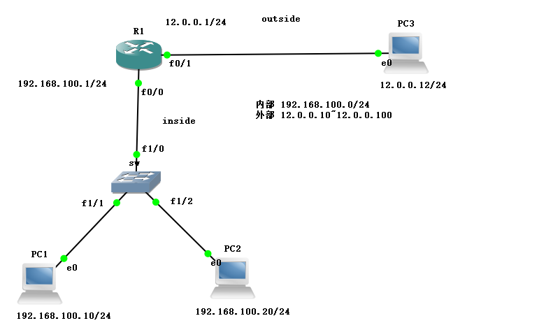
9. Dynamic NAT address translation
Dynamic NAT refers to that when the private IP address of the internal network is converted to the public IP address, the IP address pair is uncertain and random. All the private IP addresses authorized to access the Internet can be randomly converted to any specified legal IP address. In other words, as long as you specify which internal addresses can be converted and which legal addresses can be used as external addresses, you can perform dynamic conversion. Dynamic transformation can use multiple legitimate external address sets. When the legal IP address provided by ISP is slightly less than the number of computers inside the network. Dynamic transformation can be adopted.
Dynamic NAT experiment diagram
The purpose of the experiment is to transform the internal private network into one of multiple public networks.
9.1 the layer-2 switch turns off the routing function and sets the rate and full duplex mode.
sw#conf t
sw(config)#no ip routing
sw(config)#int f1/0
sw(config-if)#speed 100
sw(config-if)#dup full
sw(config-if)#ex
9.2 set address and dynamic NAT for R1 router interface
R1#conf t
R1(config)#int f0/0
R1(config-if)#ip add 192.168.100.1 255.255.255.0
R1(config-if)#no shut
R1(config-if)#int f0/1
R1(config-if)#ip add 12.0.0.1 255.255.255.0
R1(config-if)#no shut
R1(config-if)#ex
R1(config)#access-list 1 permit 192.168.100.0 0.0.0.255
//Define the internal allowed network segment, followed by the inverse code
R1(config)#ip nat pool test 12.0.0.10 12.0.0.100 netmask 255.255.255.0
//Define address segments, address ranges, start and end addresses, and subnet masks for external transformations
R1(config)#ip nat inside source list 1 pool test / / refers to the internal network segment and converts it to the address pool of the external network.
R1(config)#int f0/0
R1(config-if)#ip nat inside / / define Intranet
R1(config-if)#int f0/1
R1(config-if)#ip nat outside / / define the external network
R1(config-if)#end
R1#debug ip nat / / test to enable nat
IP NAT debugging is on
9.3. Configure IP address for each host
PC1> ip 192.168.100.10 192.168.100.1
Checking for duplicate address...
PC1 : 192.168.100.10 255.255.255.0 gateway 192.168.100.1

PC2> ip 192.168.100.20 192.168.100.1
Checking for duplicate address...
PC1 : 192.168.100.20 255.255.255.0 gateway 192.168.100.1

PC3> ip 12.0.0.12 12.0.0.1
Checking for duplicate address...
PC1 : 12.0.0.12 255.255.255.0 gateway 12.0.0.1
9.4 PC1 and PC2 hosts test whether there are multiple public network addresses when the internal network is converted to the external network.
PC1> ping 12.0.0.12
84 bytes from 12.0.0.12 icmp_seq=1 ttl=63 time=20.944 ms
84 bytes from 12.0.0.12 icmp_seq=2 ttl=63 time=18.950 ms
84 bytes from 12.0.0.12 icmp_seq=3 ttl=63 time=15.957 ms
84 bytes from 12.0.0.12 icmp_seq=4 ttl=63 time=22.452 ms
84 bytes from 12.0.0.12 icmp_seq=5 ttl=63 time=19.952 ms

*Mar  1 00:19:47.327: NAT: expiring 12.0.0.11 (192.168.100.20) icmp 34108 (34108)
R1#
*Mar  1 00:19:47.463: NAT*: s=192.168.100.20->12.0.0.11, d=12.0.0.12 [15552]
*Mar  1 00:19:47.471: NAT*: s=12.0.0.12, d=12.0.0.11->192.168.100.20 [15552]
*Mar  1 00:19:48.351: NAT: expiring 12.0.0.11 (192.168.100.20) icmp 34364 (34364)
R1#
*Mar  1 00:19:48.487: NAT*: s=192.168.100.20->12.0.0.11, d=12.0.0.12 [15553]
*Mar  1 00:19:48.499: NAT*: s=12.0.0.12, d=12.0.0.11->192.168.100.20 [15553]
*Mar  1 00:19:49.375: NAT: expiring 12.0.0.11 (192.168.100.20) icmp 34620 (34620)
R1#
*Mar  1 00:19:49.511: NAT*: s=192.168.100.20->12.0.0.11, d=12.0.0.12 [15554]
*Mar  1 00:19:49.519: NAT*: s=12.0.0.12, d=12.0.0.11->192.168.100.20 [15554]
*Mar  1 00:19:50.399: NAT: expiring 12.0.0.11 (192.168.100.20) icmp 34876 (34876)
R1#
*Mar  1 00:19:50.531: NAT*: s=192.168.100.20->12.0.0.11, d=12.0.0.12 [15555]
*Mar  1 00:19:50.543: NAT*: s=12.0.0.12, d=12.0.0.11->192.168.100.20 [15555]
*Mar  1 00:19:51.423: NAT: expiring 12.0.0.11 (192.168.100.20) icmp 35132 (35132)
R1#
10.PAT conversion
Experimental drawing
The purpose of the experiment is to transform all private network addresses into the same public network address
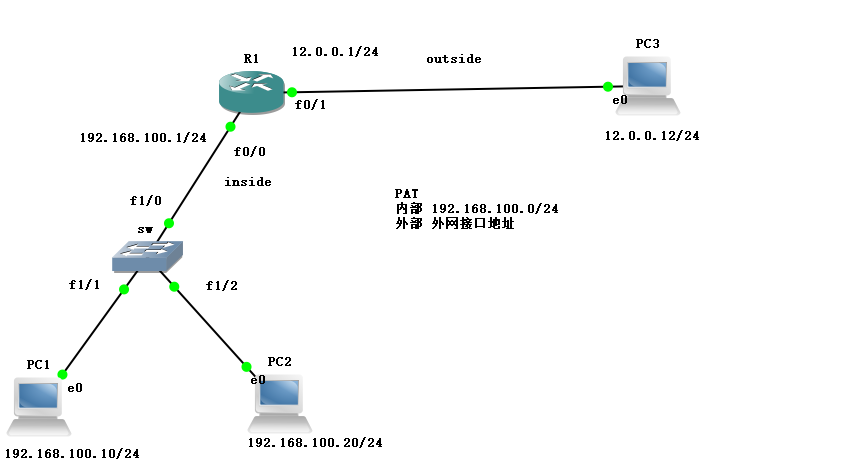
Port Address Translation, port multiplexing (port address conversion). By changing the source IP and source port of outgoing packets, and performing port conversion, all hosts in the internal network can share a common IP to access the external network, saving IP.
10.1 layer 2 switch turns off routing function, configures rate and full duplex mode
sw#conf t
sw(config)#no ip routing
sw(config)#int f1/0
sw(config-if)#speed 100
sw(config-if)#dup full
10.2R2 configure address for interface and PAT address conversion
R1#conf t
R1(config)#int f0/0
R1(config-if)#ip add 192.168.100.1 255.255.255.0
R1(config-if)#no shut
R1(config-if)#int f0/1
R1(config-if)#ip add 12.0.0.1 255.255.255.0
R1(config-if)#no shut
R1(config-if)#ex
R1(config)#Access list 1 limit 192.168.100.0.0.0.0.255 / / define the internal allowed network segments and add the inverse code.
R1(config)#ip nat inside source list 1 interface fastEthernet 0/1 overload
//Direct reference to external interfaces, overlay all external networks
R1(config)#int f0/0
R1(config-if)#ip nat in / / define Intranet
R1(config-if)#int f0/1
R1(config-if)#ip nat out / / define external network
R1(config-if)#end
R1#debug ip nat
IP NAT debugging is on  //Test start NAT
10.3 configure IP address for each host
PC1> ip 192.168.100.10 192.168.100.1
Checking for duplicate address...
PC1 : 192.168.100.10 255.255.255.0 gateway 192.168.100.1

PC2> ip 192.168.100.20 192.168.100.1
Checking for duplicate address...
PC1 : 192.168.100.20 255.255.255.0 gateway 192.168.100.1

PC3> ip 12.0.0.12 12.0.0.1
Checking for duplicate address...
PC1 : 12.0.0.12 255.255.255.0 gateway 12.0.0.1
10.4 test whether the private network addresses of PC1 and PC2 access the same public network address.
PC1> ping 12.0.0.12 -t
12.0.0.12 icmp_seq=1 timeout
84 bytes from 12.0.0.12 icmp_seq=2 ttl=63 time=20.943 ms
84 bytes from 12.0.0.12 icmp_seq=3 ttl=63 time=17.919 ms
84 bytes from 12.0.0.12 icmp_seq=4 ttl=63 time=16.956 ms

R1#
*Mar  1 00:19:04.779: NAT: s=192.168.100.10->12.0.0.1, d=12.0.0.12 [18124]
R1#
*Mar  1 00:19:06.783: NAT*: s=192.168.100.10->12.0.0.1, d=12.0.0.12 [18125]
*Mar  1 00:19:06.791: NAT*: s=12.0.0.12, d=12.0.0.1->192.168.100.10 [18125]
R1#
*Mar  1 00:19:07.807: NAT*: s=192.168.100.10->12.0.0.1, d=12.0.0.12 [18126]
*Mar  1 00:19:07.811: NAT*: s=12.0.0.12, d=12.0.0.1->192.168.100.10 [18126]
R1#
*Mar  1 00:19:08.823: NAT*: s=192.168.100.10->12.0.0.1, d=12.0.0.12 [18127]
*Mar  1 00:19:08.831: NAT*: s=12.0.0.12, d=12.0.0.1->192.168.100.10 [18127]
R1#
*Mar  1 00:19:09.843: NAT*: s=192.168.100.10->12.0.0.1, d=12.0.0.12 [18128]
*Mar  1 00:19:09.847: NAT*: s=12.0.0.12, d=12.0.0.1->192.168.100.10 [18128]
R1#

PC2> ping 12.0.0.12 -t
84 bytes from 12.0.0.12 icmp_seq=1 ttl=63 time=29.921 ms
84 bytes from 12.0.0.12 icmp_seq=2 ttl=63 time=16.981 ms
84 bytes from 12.0.0.12 icmp_seq=3 ttl=63 time=15.958 ms
84 bytes from 12.0.0.12 icmp_seq=4 ttl=63 time=23.936 ms

R1#
*Mar  1 00:20:28.715: NAT*: s=192.168.100.20->12.0.0.1, d=12.0.0.12 [18208]
*Mar  1 00:20:28.719: NAT*: s=12.0.0.12, d=12.0.0.1->192.168.100.20 [18208]
R1#
*Mar  1 00:20:29.731: NAT*: s=192.168.100.20->12.0.0.1, d=12.0.0.12 [18209]
*Mar  1 00:20:29.739: NAT*: s=12.0.0.12, d=12.0.0.1->192.168.100.20 [18209]
R1#
*Mar  1 00:20:30.751: NAT*: s=192.168.100.20->12.0.0.1, d=12.0.0.12 [18210]
*Mar  1 00:20:30.759: NAT*: s=12.0.0.12, d=12.0.0.1->192.168.100.20 [18210]
R1#
*Mar  1 00:20:31.775: NAT*: s=192.168.100.20->12.0.0.1, d=12.0.0.12 [18211]
*Mar  1 00:20:31.779: NAT*: s=12.0.0.12, d=12.0.0.1->192.168.100.20 [18211]