Blog Outline:
- I. Bridge mode (communication between containers on the same Docker server)
- 2. Deploy the consumer service to realize cross host communication of Docker container
Preface:
When you start using docker on a large scale, you will find that you need to know a lot about the network. Docker, as the most popular lightweight container technology, has many praiseworthy functions, such as image management of docker. However, docker also has many imperfections, and the network is the weak part of docker. Therefore, it is necessary for us to have a deep understanding of docker's network knowledge to meet the higher network needs. This paper first introduces four kinds of network working modes of docker itself, and then introduces some custom network modes.
When we install Docker, it will automatically create three networks: bridge (the creation container connects to this network by default), none, and host.
- Host: the container will not virtualize its own network card, configure its own IP, etc., but use the IP and port of the host.
- None: this mode turns off the network function of the container, which is equivalent to a loopback network.
- Bridge: this mode will assign and set IP for each container, and connect the container to a virtual bridge called docker0. It will communicate with the host through the docker0 bridge and Iptables nat table configuration.
[root@docker ~]# docker network ls #Execute this command to view the network created by docker
The three networks mentioned above are explained as follows:
- Host: equivalent to the bridging mode in Vmware, it is in the same network as the host, but there is no independent IP address. As we all know, Docker uses Linux's Namespaces technology to isolate resources, such as PID Namespace isolation process, Mount Namespace isolation file system, Network Namespace isolation network, etc. A Network Namespace provides an independent network environment, including network card, routing, and Iptable rules, which are isolated from other network Namespaces. A Docker container generally assigns a separate Network Namespace. However, if the host mode is used when starting the container, the container will not get a separate Network Namespace, but will share a Network Namespace with the host. The container will not virtualize its own network card, configure its own IP, etc., but use the IP and port of the host. Based on the container started in host mode, when ifconfig is executed in the container, all the information you see is the information on the host. This mode is not flexible enough, and it is prone to port conflict.
- None: this mode places the container in its own network stack, but no configuration is made. In fact, this mode turns off the network function of the container, similar to address changing, which is useful in two situations: the container does not need a network (such as batch tasks that only need to write disk volumes).
- Overlay: just as the name implies: overlay, but it is not an overlay. Its function is to add a network card based on the original network of the container, and assign an IP address to it. It can associate all the docker containers to the same LAN, which is suitable for the scenario where the container and the container are communicating across hosts.
- Bridge: equivalent to NAT mode in Vmware, the container uses independent Network nameSpace and connects to the docker0 virtual network card (default mode). Communication with the host is configured through the docker bridge and iptables NAT table. The bridge mode is the default network setting of docker, which assigns a Network nameSpace, sets IP, etc. to each container, and connects the docker container on a host to a virtual bridge docker0.
In the production environment, Bridge mode and overlay mode are the most widely used. This blog will focus on these two models.
I. Bridge mode
When the Docker server starts, a virtual bridge named docker0 will be created on the host, and the Docker container started on the host will connect to the virtual bridge. The virtual bridge works in the same way as the physical switch, so that all containers on the host are connected to a layer-2 network through the switch. Generally, Docker will use the 172.17.0.0/16 network segment, and assign this network segment to the docker0 bridge (you can see docker0 using ifconfig command on the host), and then assign an IP address of the same network segment to the container.
The network topology in the stand-alone environment is as follows (the host address is 10.10.0.186 / 24):
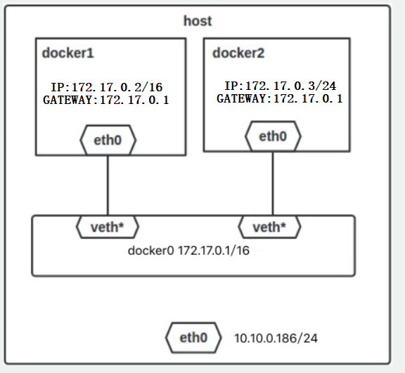
The process for Docker to complete the above network configuration is roughly as follows:
- Create a pair of virtual network card veth pair devices on the host. veth devices always appear in pairs. They form a data channel. When data enters from one device, it will come out from another device. Therefore, veth devices are often used to connect two network devices.
- Docker places one end of the veth pair device in the newly created container and names it eth0. The other end is placed in the host, named after veth65f9, and the network device is added to the docker0 bridge, which can be viewed through the brctl show command.
- Assign an IP to the container from the docker0 subnet, and set the IP address of docker0 as the default gateway of the container.
When all containers are created based on the default docker0, in theory, all containers can communicate with each other regardless of firewall, IPtables and other related settings. However, the network of docker0 comes with the system, some functions cannot be realized, and it is not flexible enough.
In fact, we can also customize the network and specify which network segment it belongs to. This is impossible for docker 0. If each container is not created based on the same network (such as docker 0), then? How can they communicate with each other?
Let's take a look at the working mode of Bridge.
The effect is as follows:
- Based on docker0 (the driver name of docker), the bridge network creates two containers, namely box1 and box2.
- Create a custom network with the network type of bridge and the name of my_net1. Create two containers box3 and Box4 based on this network (if you do not specify a network segment, you will use the network segment 172.18.0.0/16, and add a network bit based on docker0)
- Create a custom network. The network type is bridge, the name is my_net2, and the specified network segment is 172.20.18.0/24. Based on this network, create two containers, box5(ip: 172.20.18.6) and box6 (IP: 172.20.18.8).
- box2 and box3 can communicate with each other, and box4 and box5 can communicate with each other.
[root@docker ~]# docker run -itd --name box1 --network bridge busybox
#Create a container box1, and the - network option can be omitted. The default is bridge. This is just to show the command.
[root@docker ~]# docker run -itd --name box2 --network bridge busybox   #As above, create a container box2 here
[root@docker ~]# docker network create -d bridge my_net1    #Create a bridge network named my_net1
[root@docker ~]# docker run -tid --name box3 --network my_net1 busybox    #Create container box3 based on my ﹣ Net1
[root@docker ~]# docker run -tid --name box4 --network my_net1 busybox   #Ditto, create box4
[root@docker ~]# docker network create -d bridge --subnet 172.20.18.0/24 my_net2   #Create a bridge network my? Net2 and specify its network segment
[root@docker ~]# docker run -tid --name box5 --network my_net2 --ip 172.20.18.6 busybox
#Based on my net 2 network, create a container box5 and specify its IP address
[root@docker ~]# docker run -tid --name box6 --network my_net2 --ip 172.20.18.8 busybox    #Ditto
[root@docker ~]# docker network connect my_net1 box2      #Connect box2 to my Net1
[root@docker ~]# docker exec box2 ping box3   #Through the Ping test, it can be found that box2 can ping through box3.
#If the box2 is not connected to the network my ﹣ Net1, it will never ping.
PING box3 (172.18.0.2): 56 data bytes
64 bytes from 172.18.0.2: seq=0 ttl=64 time=0.069 ms
64 bytes from 172.18.0.2: seq=1 ttl=64 time=0.076 ms
[root@docker ~]# docker network connect my_net2 box4   #Connect the box4 to my ﹣ net2 network
#In the same way as box2 and box3, if box4 is not connected to the network where box5 is located, it is impossible to ping.
[root@docker ~]# docker exec box5 ip a    #View the IP address of box5
         .......................#Omit part of the content
16: eth0@if17: <BROADCAST,MULTICAST,UP,LO500 qdisc noqueue
    link/ether 02:42:ac:14:12:06 brd ff:ff:ff:ff:ff:ff
    inet 172.20.18.6/24 brd 172.20.18.255 scope global eth0     #Confirm its IP
       valid_lft forever preferred_lft forever
[root@docker ~]# docker exec box4 ping 172.20.18.6   #Ping the box5 IP on the box4 container, and you can ping the connection.
PING box5 (172.20.18.6): 56 data bytes
64 bytes from 172.20.18.6: seq=0 ttl=64 time=0.090 ms
64 bytes from 172.20.18.6: seq=1 ttl=64 time=0.130 ms
After the above configuration, the final effect has been achieved. It should be noted that we can fully understand the created network drivers of my ﹣ Net1 and my ﹣ net2 as a switch, and execute the command docker network connect my ﹣ Net1 box2, which is equivalent to adding a network card to the box2 container, then connecting to the switch of my ﹣ Net1, and then the container has an additional network. Card, and has the IP address in the switch of my_net1. In the above configuration, box2 can not only communicate with box3, but also with box4, because they are all connected to the "switch" of my ﹐ Net1.
Be careful:
- The container names can be used for communication between containers, but only if the user-defined network is used, such as my_net1 and my_net2 above;
- If the network segment of the network is specified when creating a custom network, the container of the network can also specify the IP address of the container. If the network segment of the network is not specified, the IP address of the container cannot be specified.
2. Deploy the consumer service to realize cross host communication of Docker container
Consumer: the meaning of data center can be understood as a database. Similar to non relational databases such as Redis, it uses key value pairs to store IP and port information of each container.
I don't know much about the consumer service. If you want to know more about the service, please refer to other documents. If you have a chance in the future, I will write down the consumer service in detail.
The function of consumer is very powerful, it can run in the way of cluster, and it has the function of health monitoring.
Next, start to configure the consumer service.
1. Environmental preparation is as follows:
- There are three docker servers. The docker version here is 18.09.0.
- The IP address of the first Docker server is 192.168.20.7, which runs the consumer service.
- The last two are the test end. You only need a docker environment.
If you need to install and deploy Docker server, please refer to the blog: Detailed configuration of Docker installation .
2. The first Docker server is configured as follows:
[root@docker ~]# docker pull progrium/consul          #Download the consumer image
[root@docker ~]# docker run -d -p 8500:8500 -h consul --name consul --restart=always progrium/consul -server -bootstrap
#Run the consumer container, the default port of the service is 8500, "- p": it means mapping the 8500 port of the container to the 8500 port of the host
#"- h": indicates the host name of the container; "-- name consumer" indicates the container name; "-- restart=always" indicates that it can be started with the start of the docker service;
#"- serve - bootstart": indicates that when in a cluster, these two options can be added to make it appear as a master.
[root@docker ~]# netstat -anput | grep 8500   #Make sure port 8500 is listening
tcp6       0      0 :::8500                 :::*
OK, so far, the single node consumer service is complete. Now switch to the second Docker server.
3. The configuration of the second Docker server is as follows:
[root@docker02 ~]# vim /usr/lib/systemd/system/docker.service  #Edit docker master profile
         ..............#Omit some content, search "Start" and locate to the following configuration line, modify as follows:
ExecStart=/usr/bin/dockerd -H unix:///var/run/docker.sock -H tcp://0.0.0.0:2376 --cluster-store=consul://192.168.20.7:8500 --cluster-advertise=ens33:2376
#The explanations are as follows:
#/var/run/docker.sock: a programming interface of Docker
# "- H tcp://0.0.0.0:2376": use the native tcp2376 port;
# "-- cluster store = Consumer: / / 192.168.20.7:8500": Specifies the IP and port of the first docker server running the consumer service;
# "-- cluster advertisement = ens33:2376": collect network information from the local ens33 network card through port 2376 and store it on the consumer.
#After modification, save to exit.
[root@docker02 ~]# systemctl daemon-reload    #Reload profile
[root@docker02 ~]# systemctl restart docker    #Restart docker service
4. Then on the third docker server, perform the same configuration operation as the second docker server, mainly to specify the listening port of the consumer service. (self configuration, not written here. Remember to restart the docker service after the change is completed)
5. Now use the browser to access the web page of the consumer service (visit: 192.168.20.7:8500), as follows:
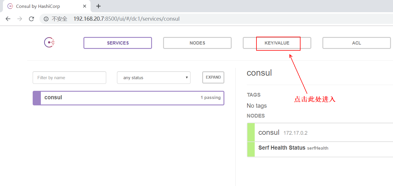
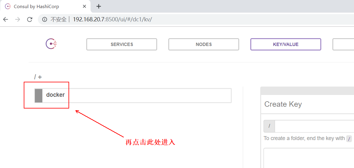
You can see the IP and other related information of the two docker servers used for testing, as follows: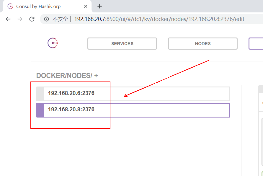
6. Go back to the second Docker server and create an overlay network:
[root@docker02 ~]# docker network create -d overlay my_olay #Create a voerlay network named my "Olay"
7. Switch to the third Docker server. You can see the overlay network just created on the second Docker server:
[root@docker03 ~]# docker network ls     #Check the network of docker03 and find that it has not only overlay network.
#And its SCOPE is global.
NETWORK ID          NAME                DRIVER              SCOPE
8d5b00cf07ab        bridge              bridge              local
17c053a80f5a        host                host                local
c428fc28bb11        my_olay             overlay             global
323935eaa5c3        none                null                local
In fact, now a container is running on the second Docker server based on the overlay network just created, and a container is running on the third Docker server based on the overlay network. The two containers on different hosts can communicate with each other, as follows:
##################Second stations Docker The configuration on the server is as follows:###########################
[root@docker02 ~]# docker run -tid --name web01 --network my_olay busybox    #Running a container web01 based on my OLAY
[root@docker02 ~]# docker exec web01 ip a         #Check the IP information and find that there are two IPS besides the loopback address.
1: lo: <LOOPBACK,UP,LOWER_UP> mtu 65536 qdisc noqueue qlen 1
    link/loopback 00:00:00:00:00:00 brd 00:00:00:00:00:00
    inet 127.0.0.1/8 scope host lo
       valid_lft forever preferred_lft forever
8: eth0@if9: <BROADCAST,MULTICAST,UP,LOWER_UP,M-DOWN> mtu 1450 qdisc noqueue
    link/ether 02:42:0a:00:00:02 brd ff:ff:ff:ff:ff:ff
    inet 10.0.0.2/24 brd 10.0.0.255 scope global eth0     #This address is given by my yuan Olay.
       valid_lft forever preferred_lft forever
11: eth1@if12: <BROADCAST,MULTICAST,UP,LOWER_UP,M-DOWN> mtu 1500 qdisc noqueue
    link/ether 02:42:ac:12:00:02 brd ff:ff:ff:ff:ff:ff
    inet 172.18.0.2/16 brd 172.18.255.255 scope global eth1
       valid_lft forever preferred_lft forever
##################Third stations Docker The configuration on the server is as follows:###########################
[root@docker03 ~]# docker run -tid --name web02 --network my_olay busybox     #Running a container web02 based on my OLAY
[root@docker03 ~]# docker exec web02 ip a     #View the IP of web02
1: lo: <LOOPBACK,UP,LOWER_UP> mtu 65536 qdisc noqueue qlen 1
    link/loopback 00:00:00:00:00:00 brd 00:00:00:00:00:00
    inet 127.0.0.1/8 scope host lo
       valid_lft forever preferred_lft forever
8: eth0@if9: <BROADCAST,MULTICAST,UP,LOWER_UP,M-DOWN> mtu 1450 qdisc noqueue
    link/ether 02:42:0a:00:00:03 brd ff:ff:ff:ff:ff:ff
    inet 10.0.0.3/24 brd 10.0.0.255 scope global eth0            #This address is given by my yuan Olay.
       valid_lft forever preferred_lft forever
11: eth1@if12: <BROADCAST,MULTICAST,UP,LOWER_UP,M-DOWN> mtu 1500 qdisc noqueue
    link/ether 02:42:ac:12:00:02 brd ff:ff:ff:ff:ff:ff
    inet 172.18.0.2/16 brd 172.18.255.255 scope global eth1
       valid_lft forever preferred_lft forever
#########At second stations. Docker On the server Docker Container on server ping test##########
[root@docker02 ~]# docker exec web01 ping web02      #Make sure you can ping
PING web02 (10.0.0.3): 56 data bytes
64 bytes from 10.0.0.3: seq=0 ttl=64 time=1.091 ms
64 bytes from 10.0.0.3: seq=1 ttl=64 time=1.007 ms
————————Thank you for reading————————