First met LoRa
In short, LoRa is a low-power remote wireless communication technology. It is a wireless data transmission module developed based on SX1276/1278 chip of Semtech company. This chip has small integration scale and high efficiency, so that LoRa module has high receiving sensitivity. So what are its advantages over our commonly used Bluetooth and WiFi? In summary, it is low power consumption, long distance and anti-interference. Under the same conditions, the transmission distance of LoRa module is longer than that of WiFi module. The common short-range wireless communication technologies such as WiFi and Bluetooth have a communication distance of only about tens of meters. If you want to cover the network of a certain region and a city, the deployment cost will be very high and not cost-effective. As a low-power wide area network LoRa technology, the wireless communication distance can reach several kilometers or even more than ten kilometers, which is much farther than WiFi module. These advantages make LoRa widely used in the current Internet of things and have developed rapidly.
Get started, LoRa
The LoRa module used in this tutorial is ATK-LORA-01 of punctual atom. The physical picture is as follows:
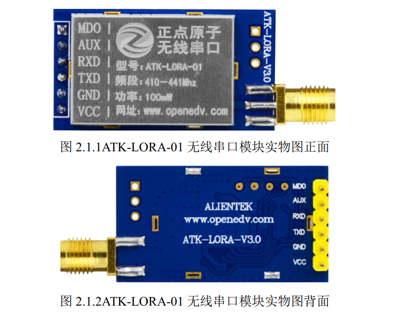
At the beginning, when I got it, it was a wireless serial port. Write about the serial port data sending and receiving, and it should be adjusted soon. But it took me a whole day to finish up and down, and of course it was due to the stinking routine and the user manual that did not understand the key points. I think you can use these modules directly. The program should be very convenient to transplant, but it's not on time. You have to add all kinds of display screens and peripheral modules in the program, and then write some complex programs. So I went online to refer to other people's programs. Combined with my own debugging experience, I rewritten the program of LoRa module, which is very convenient for transplantation.
When you get a module, you must read the user manual and data manual before programming. You must know how to use it first. I'll post some important parts of the materials given on time (related to programming modules) here. Readers can refer to the manual if they have other needs.
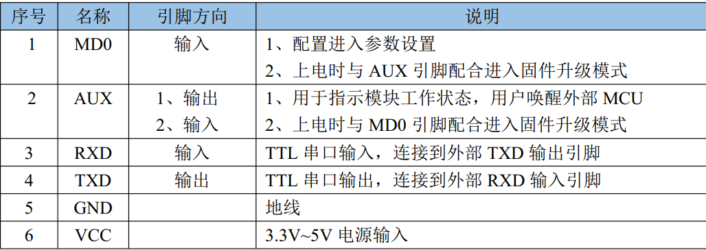
The first is the pin function description: in addition to the four common pins of the serial port, there are two more pins. Referring to its description, we can conclude that these two pins are used to configure module communication. Because they are wireless serial ports, it is certain that the two modules must have the same configuration to communicate.
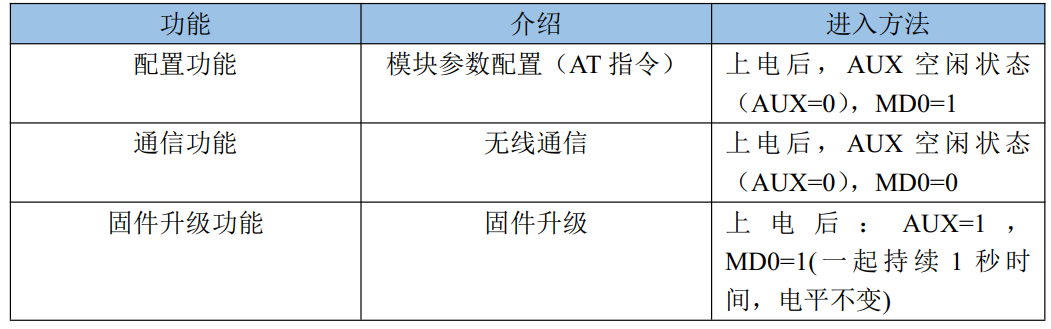
The following is the description of these two configuration pins, which is related to how we make the module in different working states: obviously, when AUX and MD0 pins are at low level, it is the communication function of the module (that is, the two LoRa modules send and receive data from each other). When we first pair it, we need to enter the configuration function. At this time, we need the MD0 pin to be high. Then we know from the manual that MD0 and AUX pins are low when suspended.
In other words, after we have paired the two modules, we can not connect the wires of MD0 and AUX pins, let them hang at a low level, and the two modules can communicate. In this way, it is basically no different from the serial port, and the program will be simplified accordingly.
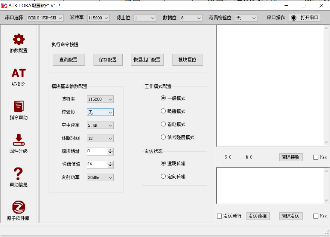
So how to pair the two modules? My personal suggestion is to connect a USB to TTL to the computer, and then set it with the upper computer provided on time. In this way, we can not care about the writing method and meaning of AT instructions, and achieve the fastest start-up and use LoRa module. Here, after the connection is completed, modify the basic parameter configuration of the module. The working mode configuration and sending status remain the default first. In the module parameter configuration, the two modules must be consistent. I personally suggest that the communication channel and module address can be modified to reduce interference (just in case).
Once our modules are paired, the programming logic is very simple, just the receiving and sending of serial port. Of course, we can write operations such as module configuration in the program, but imagine that we need to connect two pin lines and write a lot of logic control. Why not pair it first and then use it as a serial port?
Programming
My purpose here is to enable stm32 and computer to realize wireless communication through two LoRa modules, and both can display the received and sent data. The MCU side allows LoRa to use serial port 3, and then prints the data at the receiving end of serial port 3 on the computer through serial port 1.
usart3.h. preparation:
#ifndef __USART3_H
#define __USART3_H
#include "sys.h"


#define USART3_MAX_RECV_LEN 		 one thousand and twenty-four 			    // Maximum receive cache bytes
#define USART3_MAX_SEND_LEN 		 six hundred 					// Maximum send cache bytes
#define USART3_RX_EN  			 one 					// 0, not received; 1. Receive

extern u8  USART3_RX_BUF[USART3_MAX_RECV_LEN]; 		//Receive buffer, maximum USART3_MAX_RECV_LEN byte
extern u8  USART3_TX_BUF[USART3_MAX_SEND_LEN]; 		//Send buffer, maximum USART3_MAX_SEND_LEN byte
extern vu16 USART3_RX_STA;   						//Receive data status

void usart3_init(u32 bound);		//Serial port 2 initialization
void usart3_set(u8 bps,u8 parity);
void usart3_rx(u8 enable);
void u3_printf(char* fmt,...);
#endif
usart3.c. preparation:
#include "delay.h"
#include "usart3.h"
#include "stdarg.h"
#include "stdio.h"
#include "string.h"
#include "timer.h"


extern u8 Lora_mode;
//Serial port receiving buffer
u8 USART3_RX_BUF[USART3_MAX_RECV_LEN]; 			//Receive buffer, maximum USART3_MAX_RECV_LEN bytes
u8 USART3_TX_BUF[USART3_MAX_SEND_LEN]; 			//Send buffer, maximum USART3_MAX_SEND_LEN byte
u8 Temp;
//Determine whether it is continuous data at one time by judging that the time difference between two consecutive characters is no more than 10ms
//If the receiving interval of two characters exceeds timer, it is not considered as one continuous data That is, it is not received after the timer
//Any data indicates that the reception is completed
//Received data status
//[15] : 0, no data received; 1. Received a batch of data
//[14:0]: received data length
vu16 USART3_RX_STA=0;

void USART3_IRQHandler(void)
{
	u8 res;
	if(USART_GetITStatus(USART3, USART_IT_RXNE) != RESET)//Data received
	{
		res =USART_ReceiveData(USART3);
		if((USART3_RX_STA&(1<<15))==0)              //If a batch of received data has not been processed, no other data will be received
		{
			if(USART3_RX_STA<USART3_MAX_RECV_LEN)	//Data can also be received
			{
				if(!Lora_mode)//Under configuration function (start timer timeout)
				{
					TIM_SetCounter(TIM7,0);             //Counter clear
					if(USART3_RX_STA==0) 				//Interrupt of enable timer 7
					{
						TIM_Cmd(TIM7,ENABLE);           //Enable timer 7
					}
				}
				USART3_RX_BUF[USART3_RX_STA++]=res;	//Record the received value
			}else
			{
				USART3_RX_STA|=1<<15;				//Force mark reception complete
			}
		}
	}


}

USART_InitTypeDef USART_InitStructure;
//Initialize IO serial port 3
//pclk1:PCLK1 clock frequency (Mhz)
//bound: baud rate
void usart3_init(u32 bound)
{

	NVIC_InitTypeDef NVIC_InitStructure;
	GPIO_InitTypeDef GPIO_InitStructure;

	RCC_APB2PeriphClockCmd(RCC_APB2Periph_GPIOB, ENABLE); // GPIOB clock
	RCC_APB1PeriphClockCmd(RCC_APB1Periph_USART3,ENABLE); //Serial port 3 clock enable

 	USART_DeInit(USART3);                           //Reset serial port 3
   //USART3_TX   PB10
	GPIO_InitStructure.GPIO_Pin = GPIO_Pin_10;      //PB10
	GPIO_InitStructure.GPIO_Speed = GPIO_Speed_50MHz;
	GPIO_InitStructure.GPIO_Mode = GPIO_Mode_AF_PP;	//Multiplexed push-pull output
	GPIO_Init(GPIOB, &GPIO_InitStructure);          //Initialize PB10

	//USART3_RX	  PB11
	GPIO_InitStructure.GPIO_Pin = GPIO_Pin_11;
	GPIO_InitStructure.GPIO_Mode = GPIO_Mode_IN_FLOATING;           //Floating input
	GPIO_Init(GPIOB, &GPIO_InitStructure);                          //Initialize PB11

	USART_InitStructure.USART_BaudRate = bound;                     //The baud rate is generally set to 9600;
	USART_InitStructure.USART_WordLength = USART_WordLength_8b;     //The word length is in 8-bit data format
	USART_InitStructure.USART_StopBits = USART_StopBits_1;          //A stop bit
	USART_InitStructure.USART_Parity = USART_Parity_No;             //No parity bit
	USART_InitStructure.USART_HardwareFlowControl = USART_HardwareFlowControl_None;//No hardware data flow control
	USART_InitStructure.USART_Mode = USART_Mode_Rx | USART_Mode_Tx;	//Transceiver mode

	USART_Init(USART3, &USART_InitStructure); //Initialize serial port 3

	USART_Cmd(USART3, ENABLE);                  //Enable serial port

	//Enable receive interrupt
    USART_ITConfig(USART3, USART_IT_RXNE, ENABLE);//Open interrupt

	//Set interrupt priority
	NVIC_InitStructure.NVIC_IRQChannel = USART3_IRQn;
	NVIC_InitStructure.NVIC_IRQChannelPreemptionPriority=2 ;//Preemption priority 3
	NVIC_InitStructure.NVIC_IRQChannelSubPriority = 3;		//Sub priority 3
	NVIC_InitStructure.NVIC_IRQChannelCmd = ENABLE;			//IRQ channel enable
	NVIC_Init(&NVIC_InitStructure);	//Initializes the VIC register according to the specified parameters

	TIM7_Int_Init(99,7199);	//10ms interrupt
	USART3_RX_STA=0;		//Clear
	TIM_Cmd(TIM7,DISABLE);	//Turn off timer 7
}

//Serial port 3,printf function sending end, LORA module sending data
//Ensure that the data sent at one time does not exceed USART3_MAX_SEND_LEN byte
void u3_printf(char* fmt,...)
{
	u16 i,j;
	va_list ap;
	va_start(ap,fmt);
	vsprintf((char*)USART3_TX_BUF,fmt,ap);  //Send formatted output to string using parameter list
	va_end(ap);
	i=strlen((const char*)USART3_TX_BUF);		//Length of data sent this time
	for(j=0;j<i;j++)							//Send data circularly
	{
	  while(USART_GetFlagStatus(USART3,USART_FLAG_TC)==RESET); //Cycle sending until sending is completed
	  USART_SendData(USART3,USART3_TX_BUF[j]);
	}
}


//Serial port receiving enable control
//enable:0, close 1, open
void usart3_rx(u8 enable)
{
	 USART_Cmd(USART3, DISABLE); //Disabled serial port

	 if(enable)
	 {
		 USART_InitStructure.USART_Mode = USART_Mode_Rx | USART_Mode_Tx;//Transceiver mode
	 }else
	 {
		 USART_InitStructure.USART_Mode = USART_Mode_Tx;//insurance against total loss only
	 }

	 USART_Init(USART3, &USART_InitStructure); //Initialize serial port 3
   USART_Cmd(USART3, ENABLE); //Enable serial port

}
lora.h. preparation:
#ifndef __LORA_H
#define __LORA_H
#include "sys.h"


void LoRa_Process(void);
void LoRa_SendData(void);
void LoRa_ReceData(void);
void Lora_Test(void);

#endif
lora.c. preparation:
#include "lora.h"
#include "sys.h"
#include "delay.h"
#include "usart3.h"
#include "string.h"
#include "stdio.h"
#include "usart.h"
#include "led.h"
#include "key.h"


//Equipment working mode (used to record equipment status)
u8 Lora_mode=0;//0: configuration mode

extern u8 USART_RX_BUF[USART_REC_LEN];     //Receive buffer, maximum USART_REC_LEN bytes
EXTI_InitTypeDef EXTI_InitStructure;
NVIC_InitTypeDef NVIC_InitStructure;


//LORA module sends data
void LoRa_SendData(void)
{
    	u8 temp[256] = "Hello Lora !!!";

			u3_printf("%s\r\n",temp);

}


//Lora module receives data
void LoRa_ReceData(void)
{
		u16 len=0;

  if(USART3_RX_STA&0x8000)
	{
		len = USART3_RX_STA&0X7FFF;
		USART3_RX_BUF[len]=0;//Add Terminator
		USART3_RX_STA=0;
		printf("The data received is");
		printf("%s\r\n",USART3_RX_BUF);
  }

}

//Send and receive data processing process
void LoRa_Process(void)
{
	 u8 key=0;
	 u8 t=0;
	 static u8 n = 1;

   while(1)
		{
			if(n==1)
			{
			 printf("Press KEY0 send data\r\n");
			 n++;
			}
	     key = KEY_Scan(0);
	    if(key==KEY0_PRES)
			{
				if(n==2)
				{
					printf("KEY0 Pressed\r\n");
				  LoRa_SendData();//send data
					printf("Data has been sent\r\n");
				}
			}
		  LoRa_ReceData();
		  t++;
			if(t==20)
			{
					t=0;
					LED1=~LED1;
			}
						delay_ms(10);

	  }
}


void Lora_Test(void)
{
	  u8 t=0;
		u8 key=0;

		while(1)
		{

			printf("Press KEY_UP Enter data test\r\n");
		  key = KEY_Scan(0);
			if(key==WKUP_PRES)
			{
	      printf("Enter data test\r\n");
			  LoRa_Process();//Start data test
			}
				 t++;
				if(t==30)
				{
					t=0;
					LED1=~LED1;
				}
				delay_ms(10);
		}
}
main.c. preparation:
#include "sys.h"
#include "delay.h"
#include "usart.h"
#include "key.h"
#include "led.h"
#include "lora.h"
#include "timer.h"
#include "usart3.h"


int main(void)
 {
	NVIC_PriorityGroupConfig(NVIC_PriorityGroup_2);//Set the interrupt priority group as 2: 2-bit preemption priority and 2-bit response priority
	delay_init();	    	 //Delay function initialization
	uart_init(115200);	 //The serial port is initialized to 115200
	usart3_init(115200);  //Serial port 3 is initialized to 115200
	usart3_rx(1);//Enable serial port 3 reception
	LED_Init();
	KEY_Init();
	printf("LORA Module test procedure start\r\n");

	Lora_Test();//Master test

}
When porting a program, you only need to use USART h,usart.c,lora.h,lora.c can be included in your project. You can also transplant only Lora C and Lora H then modify serial port 3 to the serial port you use. (compared with the complex and huge project on schedule, I think these modules are still so easy to use)
Result demonstration
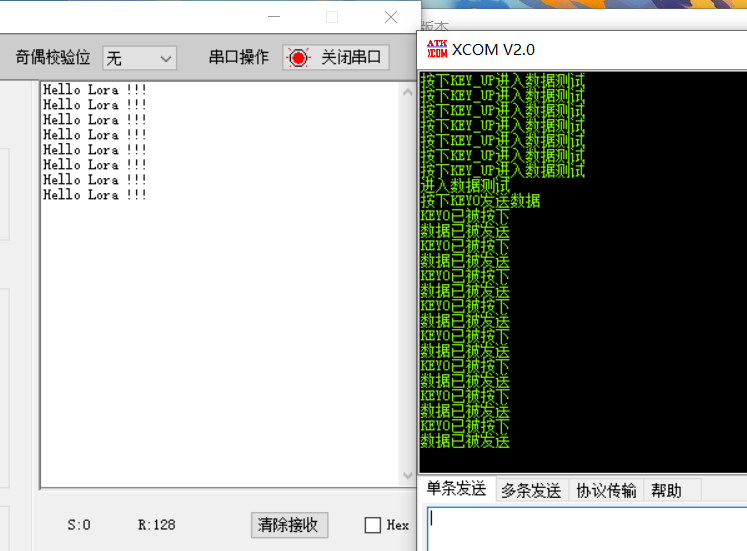
Data sending effect:
Data receiving effect:
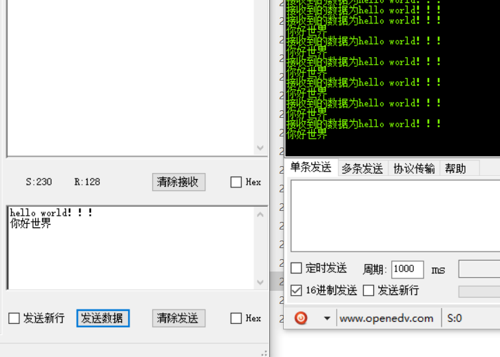
Here you can open two serial port assistants. One is used to view the data of LoRa module connected to MCU and the other is used to view the data of LoRa module connected to computer. It is still very easy to understand.
Bye, LoRa
I can get the complete project code and the private chat with LoRa configuration code. Help everyone get started and use LoRa quickly!