Sky box or The sky dome provides an effective and relatively simple method to generate a convincing horizon landscape.
Sky box
- How do I texture the horizon?
The cube has six faces, and we need to texture all of them.
One method is to use 6 image files and 6 texture units.
Another common (and efficient) way is to use an image with a texture of six faces.
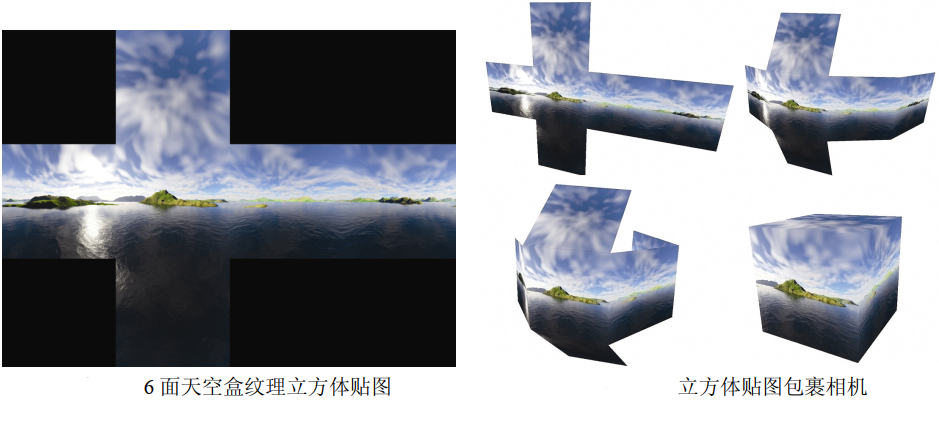
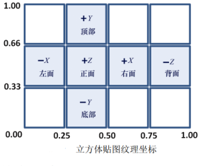
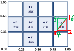
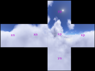
Adding a texture to a cube using a texture cube map requires specifying the appropriate texture coordinates. The following figure shows the texture
These coordinates are then assigned to each vertex of the cube.
- How to make the sky box look "far away"?
By using the following two techniques, you can make the sky box look huge (and feel far away):
(a) Disable the depth test and render the skybox first (re enable the depth test when rendering other objects in the scene);
(b) The skybox moves with the camera (if the camera needs to move).
By drawing the skybox first with the depth test disabled, the value of the depth buffer will still be all set to 1.0 (i.e. farthest)
Distance). Therefore, all other objects in the scene will be fully rendered, that is, the sky box will not block any other objects. this
Like, regardless of the actual size of the sky box, the positions of all sides of the sky box will look farther than other objects. and
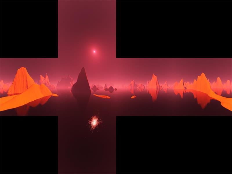
The actual skybox cube itself can be very small, as long as it moves with the camera when the camera moves. The following figure shows a simple scene viewed from inside the skybox.
The part of the sky box visible in the scene is the rightmost part of the cube map. This is because the camera is in the default direction, facing the − Z direction, so you are looking at the back of the skybox cube (as shown in the "cube map texture coordinates" Figure). Also note that the back of the cube map is reversed horizontally when rendered in the scene; This is because the "back" part of the cube map has been folded around the camera, so it looks like it has been flipped laterally (as shown in the two figures at the top of the article). - How do I build texture cube maps?
When building texture cube map images from artwork or photos, you need to pay attention to avoiding "seams" at the intersection of cube faces and create correct perspective to make the sky box look realistic and distortion free. There are many tools that can help achieve this goal: Terragen, Autodesk 3Ds Max, Blender and Adobe Photoshop all have tools for building or processing cube maps. At the same time, there are many websites that provide all kinds of ready-made cube maps.
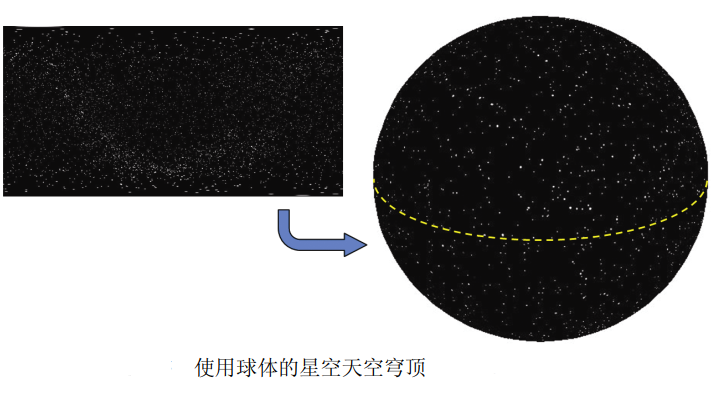
sky dome
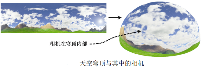
Another way to create a horizon effect is to use the sky dome. In addition to using a textured sphere (or hemisphere) instead of a textured cube, its basic idea is the same as the sky box. Like the sky box, we first render the sky dome (disable the depth test) and keep the camera in the center of the sky dome (the sky dome texture in the figure below is made using Terragen).
The sky dome has its own advantages over the sky box. For example, they are not susceptible to distortion and seams (although spherical distortion at the poles must be considered in texture images).
One of the disadvantages of the sky dome is that the sphere or dome model is more complex than the cube model. The sky dome has more vertices, and its number depends on the desired accuracy.
When the sky dome is used to present an outdoor scene, it is usually combined with the ground plane or some terrain. When using the sky dome to render scenes in the universe (such as the starry sky), it is usually more practical to use the sphere shown in the following figure (a dotted line is added to the surface of the sphere in order to clearly visualize the sphere).
Realize sky box
Although the sky dome has many advantages, the sky box is still more common. OpenGL also has better support for skybox, which is more convenient for environment mapping (described later in this chapter). For these reasons, we will focus on the implementation of skybox. There are two ways to implement skybox: build a simple skybox from scratch; Or use the cube mapping tool in OpenGL. They have their own advantages.
Build skybox from scratch
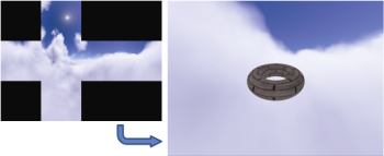
Here, we'll see how to simply enable and disable deep testing (just one line of code). The scene contains only one textured torus.
//All variable declarations, constructors and init() are the same as before
. . .
void display(GLFWwindow* window, double currentTime) {
	// Clear the color buffer and depth buffer, and create the projection view matrix and camera view matrix as before
	. . .
	vMat = glm::translate(glm::mat4(1.0f), glm::vec3(-cameraX, -cameraY, -cameraZ));
	glUseProgram(renderingProgram);
	// Prepare to draw the sky box first. The M matrix places the skybox at the camera position
	// Note: mMat is certainly not a negative camera position, because the camera position in world space is (cameraX,cameraY,cameraZ)
	mMat = glm::translate(glm::mat4(1.0f), glm::vec3(cameraX, cameraY, cameraZ));
	// Build MODEL-VIEW matrix
	mvMat = vMat * mMat;
	// Put the variables in front of the matrix, such as MV and J
	. . .
	// Sets the buffer containing vertices
	glBindBuffer(GL_ARRAY_BUFFER, vbo[0]);
	glVertexAttribPointer(0, 3, GL_FLOAT, GL_FALSE, 0, 0);
	glEnableVertexAttribArray(0);
	// Sets the buffer containing texture coordinates
	glBindBuffer(GL_ARRAY_BUFFER, vbo[1]);
	glVertexAttribPointer(1, 2, GL_FLOAT, GL_FALSE, 0, 0);
	glEnableVertexAttribArray(1);
	//Activate skybox texture
	glActiveTexture(GL_TEXTURE0);
	glBindTexture(GL_TEXTURE_2D, skyboxTexture);
	glEnable(GL_CULL_FACE);
	// The winding order of the cube is clockwise, but we view it from the inside, so we use the counterclockwise winding order: GL_CCW
	glFrontFace(GL_CCW);
	// Draw the sky box [without depth test]
	glDisable(GL_DEPTH_TEST);
	glDrawArrays(GL_TRIANGLES, 0, 36);
	glEnable(GL_DEPTH_TEST);
	//Now paint the objects in the scene as before
	. . .
	glDrawElements( . . . ); //Just like the objects in the previous scene
}

void setupVertices(void) {
	// cube_ The definitions of vertices are the same as before
	// The cube texture coordinates of the sky box, as shown in the figure "cube map texture coordinates"
	float cubeTextureCoord[72] = {
		1.00f, 0.66f, 1.00f, 0.33f, 0.75f, 0.33f, // Lower right corner of back
		0.75f, 0.33f, 0.75f, 0.66f, 1.00f, 0.66f, // Upper left corner of back
		0.75f, 0.33f, 0.50f, 0.33f, 0.75f, 0.66f, // Right lower right corner
		0.50f, 0.33f, 0.50f, 0.66f, 0.75f, 0.66f, // Right upper left corner
		0.50f, 0.33f, 0.25f, 0.33f, 0.50f, 0.66f, // Lower right corner of front
		0.25f, 0.33f, 0.25f, 0.66f, 0.50f, 0.66f, // Upper left corner of front
		0.25f, 0.33f, 0.00f, 0.33f, 0.25f, 0.66f, // Left lower right corner
		0.00f, 0.33f, 0.00f, 0.66f, 0.25f, 0.66f, // Left upper left corner
		0.25f, 0.33f, 0.50f, 0.33f, 0.50f, 0.00f, // Lower right corner
		0.50f, 0.00f, 0.25f, 0.00f, 0.25f, 0.33f, // Lower upper left corner
		0.25f, 1.00f, 0.50f, 1.00f, 0.50f, 0.66f, // Upper right lower corner
		0.50f, 0.66f, 0.25f, 0.66f, 0.25f, 1.00f  // Upper left corner
	};
	//Set buffers for cubes and scene objects as usual
}
	//Modules for loading shaders, textures, main(), etc., as before
The picture of sky box given is as follows:
The running effect of the program is as follows:
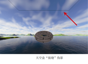
Skybox is vulnerable to image distortion and seams. Seam refers to the place where two texture images contact (ratio)
Visible lines that sometimes appear, such as along the edge of a cube. The following figure shows an example of a seam in the upper half of the image, which is an artifact when running the above program. To avoid seams, you need to carefully build the cube map image and assign precise texture coordinates. There are tools that you can use to reduce seams along the edges of an image (for example, the GNU Image Manipulation Program).
Using OpenGL cube mapping
Another way to build skyboxes is to use OpenGL texture cube maps. OpenGL cube mapping is a little more complex than the simple method we saw above. However, using OpenGL cube mapping has its own advantages, such as reducing seams and supporting environment mapping.
OpenGL texture cube maps are similar to 3D textures that will be studied later. They are accessed using three texture coordinates -- usually marked as (s, t, r).
OpenGL texture cube map, in which the image takes the [upper left corner] of the texture image as (0, 0, 0).
The above program reads in a single image to add texture to the cube map, and here we will use the loadCubeMap() function to read in six separate cube surface image files.
Here, SOIL2 is also very convenient for instantiating and loading OpenGL cube maps.
When using OpenGL cube mapping, OpenGL automatically processes the texture without flipping it vertically.
The init() function now contains a function call to enable GL_TEXTURE_CUBE_MAP_SEAMLESS, which tells OpenGL to try to blend the adjacent edges of the cube to reduce or eliminate seams.
In display(), the vertices of the cube are sent down the pipeline as before, but the texture coordinates of the cube do not need to be sent this time. As we will see, OpenGL texture cube mapping usually uses the vertex position of the cube as its texture coordinates. Then disable the depth test and draw the cube. Then re enable depth testing for the rest of the scene.
The completed OpenGL texture cube map is referenced with an identifier of type int. As with shadow mapping, you can reduce artifacts along the border by setting the texture wrap mode to clamp to edge. In this case, it can also help to further reduce the joint. Note that you need to set the texture wrap mode for all three texture coordinates s, t, and r.
Use a special type of sampler called samplerCube in the clip shader to access the texture. In the texture cube map, the value returned from the sampler is the texture element "seen" from the origin along the direction vector (s, t, r). Therefore, we can usually simply use the incoming interpolated vertex positions as texture coordinates. In the vertex shader, we assign cube vertex positions to the output texture coordinate attribute for interpolation when they reach the clip shader. Also note that in the vertex shader, we convert the passed in view matrix to 3 × 3, and then back to 4 × 4. This "trick" effectively removes the translation component while retaining the rotation. This fixes the cube map to the camera position while still allowing the composite camera to "look around".
The storage of matrix median and the principle of mat4 to mat3 are analyzed
The translation matrix, scaling matrix and transformation matrix rotating around the axis are as follows:
(
flat
shift
change
change
)
(
X
+
T
x
Y
+
T
y
Z
+
T
z
1
)
=
[
1
0
0
T
x
0
1
0
T
y
0
0
1
T
z
0
0
0
1
]
×
(
X
Y
Z
1
)
(
shrink
discharge
change
change
)
(
X
∗
S
x
Y
∗
S
y
Z
∗
S
z
1
)
=
[
S
x
0
0
0
0
S
y
0
0
0
0
S
z
0
0
0
0
1
]
×
(
X
Y
Z
1
)
(
Round
X
axis
Spin
turn
)
(
X
′
Y
′
Z
′
1
)
=
[
1
0
0
0
0
c
o
s
θ
−
s
i
n
θ
0
0
s
i
n
θ
c
o
s
θ
0
0
0
0
1
]
×
(
X
Y
Z
1
)
(
Round
Y
axis
Spin
turn
)
(
X
′
Y
′
Z
′
1
)
=
[
c
o
s
θ
0
s
i
n
θ
0
0
1
0
0
−
s
i
n
θ
0
c
o
s
θ
0
0
0
0
1
]
×
(
X
Y
Z
1
)
(
Round
Z
axis
Spin
turn
)
(
X
′
Y
′
Z
′
1
)
=
[
c
o
s
θ
−
s
i
n
θ
0
0
s
i
n
θ
c
o
s
θ
0
0
0
0
1
0
0
0
0
1
]
×
(
X
Y
Z
1
)
(translation of the translation of the transform) \ left ((the translation of the translation of the translation of the translation of the translation of the rest of the translation of the translation of the translation of the translation of the translation of the text of the last last of the country '' '\ \ \ {{atthe top of the labour labour in the array {{{{{{{{{{{{{{{{{{{{{{{{{{{{{{{{{{{{{{{{{{{{{{{{{{{{{{{{{{{{{{{{{{{{{{{{{{{{{{{{{{{{{{{{{{{{{{{{{{{{{{{{{{{{{{{{{{{{{{{{{{1 1 1 1 {0} & {0} & {0} & {1} \ end {array} \ right] \ times \ left (\ begin {array} {l} {x} \ {y}\ {{{{{{{{{array {{{array} {{{{{{{{{{{{{{{{{{{{array} \ right \ \ \ \ \ \ \ \ {{array {{{{{{{{{{{{{{{{{{{array {{{{{{{{}} {& {0} & {s_z} & {0} \ \ {0} & {0} & {0} & {1} \ end {array} \ right] \ times \ left (\ begin {array} {l} {x} \ {y} \ {Z} \ {1} \ end {array} \ right) \ \ (rotate around X axis) \ left (\ begin {array} {l} {X '} \ {y'} \ {Z '} \ {1} \ end {array} \ right) = \ left [\ begin {array} {l} {1} & {0} & {0} \ {0} & {cos θ } & { -sin θ } & { 0 } \ { 0 } & { sin θ } & { cos θ } & {{{{{{{{{{{{{{{{{{{{{{{{{{{{{{{{{{{{array {array {array}}} {{{{{{{{{{cos} θ } & { 0 } & { sin θ } & { 0 } \ { 0 } & { 1 } & { 0 } & { 0 } \ { -sin θ } & { 0 } & { cos θ } & {{{{{{{{{{{{{{{{{{{{{{{{{{{{{{{{{{array {array {array {array}}} {{{{{{{{cos} θ } & { -sin θ } & { 0 } & { 0 } \ { sin θ } & { cos θ } & { 0 } & { 0 } \ { 0 } & { 0 } & { 1 } & { 0 } \ { 0 } & { 0 } & { 0 } & { 1 } \end{array} \right] \times \left( \begin{array} { l } { X } \ { Y } \ { Z } \ { 1 } \end{array} \right)
(translation transformation) ⎝⎜⎜⎛ X+Tx ⎠⎟⎟⎞ = ⎣⎢⎢⎡ 1000 0100 ⎠ Tx ⎜⎛ X+Tx ⎦⎥⎥⎤ × ⎝⎜⎜⎛ xyz1 ⎠⎟⎟⎞ (scaling transformation) ⎝⎜⎜⎛ x * Sx Y * Sy Z * Sz 1 ⎠⎟⎟⎞ = ⎣⎢⎡ Sx 000 0Sy 00 SZ 0 0001 ⎦⎥⎤ × ⎝⎜⎜⎛ xyz1 ⎠⎟⎟⎞ (rotating about X axis) ⎝⎜⎛ x ′ Y ′ Z ′ 1 ⎠⎟⎞ = ⎣⎢⎡ 1000 0cos θ sin θ 00−sin θ cos θ 00001⎦⎥⎥⎤ × ⎝⎜⎜⎛ xyz1 ⎠⎟⎟⎞ (rotating about Y axis) ⎝⎜⎛ x ′ Y ′ Z ′ 1 ⎠⎟⎞ = ⎣⎢⎡ cos θ 0−sin θ 00100sin θ 0cos θ 00001⎦⎥⎥⎤ × ⎝⎜⎜⎛ xyz1 ⎠⎟⎟⎞ (rotating about Z axis) ⎝⎜⎛ x ′ Y ′ Z ′ 1 ⎠⎟⎞ = ⎣⎢⎡ cos θ sin θ 00−sin θ cos θ 0000100001⎦⎥⎥⎤ × ⎝⎜⎜⎛XYZ1⎠⎟⎟⎞
If you don't need the above "skills", use the above code:
float cameraX = 0.0f; cameraY = 0.0f; cameraZ = 5.0f;
vMat = glm::translate(glm::mat4(1.0f), glm::vec3(-cameraX, -cameraY, -cameraZ));
mMat = glm::translate(glm::mat4(1.0f), glm::vec3(cameraX, cameraY, cameraZ));
mvMat = vMat * mMat;
That is, the sky box is placed at the camera position, and then the MV matrix is obtained.
If you use the "tips" above, debug:
Suppose there is transMat = glm::translate(glm::mat4(1.0f), glm::vec3(5, 6, 7));
transRotMat = glm::rotate(testMat, toRadians(30), glm::vec3(1, 1, 1));
Print transMat Object: (note, OpenGL (data is organized by column)
[0][0]=1 [0][1]=0 [0][2]=0 [0][3]=0              1   0   0   5
[1][0]=0 [1][1]=1 [1][2]=0 [1][3]=0              0   1   0   6
[2][0]=0 [2][1]=0 [2][2]=1 [2][3]=0              0   0   1   7
[3][0]=5 [3][1]=6 [3][2]=7 [3][3]=1              0   0   0   1
 Print transRotMat Object:
[0][0]=0.910684 [0][1]=0.333333 [0][2]=-0.244017 [0][3]=0
[1][0]=-0.244017 [1][1]=0.910684 [1][2]=0.333333 [1][3]=0
[2][0]=0.333333 [2][1]=-0.244017 [2][2]=0.910684 [2][3]=0
[3][0]=0 [3][1]=0 [3][2]=-5 [3][3]=1
 Namely:
0.910684   -0.244017   0.333333   [5]
0.333333   0.910684   -0.244017   [6]
-0.244017  0.333333   0.910684    [7]
	0		   0		0	      [1]
Print mat4(mat3(testMat))Object:
[0][0]=0.910684 [0][1]=0.333333 [0][2]=-0.244017 [0][3]=0
[1][0]=-0.244017 [1][1]=0.910684 [1][2]=0.333333 [1][3]=0
[2][0]=0.333333 [2][1]=-0.244017 [2][2]=0.910684 [2][3]=0
[3][0]=0 [3][1]=0 [3][2]=0 [3][3]=1
 Namely:
0.910684   -0.244017   0.333333   [0]
0.333333   0.910684   -0.244017   [0]
-0.244017  0.333333   0.910684    [0]
	[0]	 [0]      [0]	  [1]

It can be seen from the object of the above data:
mat4 turn mat3 Is to remove the last column and the last row;
mat3 turn mat4 Add in the rightmost column and the lowest row[0 0 0 1]Completed.
transRotMat Through first turn mat3 Turn back mat4,The translation component is removed while the rotation is preserved.
The VIEW matrix (negative camera position matrix) is used to convert the MODEL to VIEW space.
However, the skybox does not need to be transformed according to the camera space. It is an absolute position, so the skybox MODEL can retain the rotation and remove the translation transformation.
Then, the position, translation and rotation are expressed in the VIEW matrix (there is no scaling for the camera), and the removal of the fourth column of the matrix does not affect the position, rotation and scaling. Therefore, the operation of removing the translation component can be completed through mat4 - > mat3 - > mat4.
. . .
int brickTexture, skyboxTexture;
int renderingProgram, renderingProgramCubeMap;
. . .
void init(GLFWwindow* window) {
	renderingProgram = Utils::createShaderProgram("vertShader.glsl", "fragShader.glsl");
	renderingProgramCubeMap = Utils::createShaderProgram("vertCubeShader.glsl", "fragCubeShader.glsl");
	setupVertices();
	brickTexture = Utils::loadTexture("brick.jpg");// Torus in scene
	skyboxTexture = Utils::loadCubeMap("cubeMap");// Folder containing skybox textures
	glEnable(GL_TEXTURE_CUBE_MAP_SEAMLESS);// Blend the adjacent edges of the cube to reduce or eliminate seams
}
void display(GLFWwindow* window, double currentTime) {
	// Clear the color buffer and depth buffer, and create the projection view matrix and camera view matrix as before
	. . .
	// You're ready to draw the skybox first - notice that its renderer is now different
	glUseProgram(renderingProgramCubeMap);
	// Pass the P and V matrices into the corresponding unified variables
	. . .
	// The vertices of the cube are sent down the pipeline as before
	// Initialize the vertex buffer of the cube (texture coordinate buffer is no longer required here)
	// OpenGL texture cube mapping usually uses the vertex position of the cube as its texture coordinates.
	glBindBuffer(GL_ARRAY_BUFFER, vbo[0]);
	glVertexAttribPointer(0, 3, GL_FLOAT, GL_FALSE, 0, 0);
	glEnableVertexAttribArray(0);
	// Activate cube map texture
	glActiveTexture(GL_TEXTURE0);
	glBindTexture(GL_TEXTURE_CUBE_MAP, skyboxTexture);
	// Turn off the depth test and paint the cube map
	glEnable(GL_CULL_FACE);
	glFrontFace(GL_CCW);
	glDisable(GL_DEPTH_TEST);
	glDrawArrays(GL_TRIANGLES, 0, 36);
	glEnable(GL_DEPTH_TEST);
	// Draw the rest of the scene
	. . .
	// There are also bound texture unit codes below:
	...
	glActiveTexture(GL_TEXTURE0);
	glBindTexture(GL_TEXTURE_2D, brickTexture);
	...
}
GLuint Utils::loadCubeMap(const char *mapDir) {
	GLuint textureRef;
	// Suppose that the six texture image files xp, xn, yp, yn, zp and zn are JPG format images
	string xp = mapDir; xp = xp + "/xp.jpg";
	string xn = mapDir; xn = xn + "/xn.jpg";
	string yp = mapDir; yp = yp + "/yp.jpg";
	string yn = mapDir; yn = yn + "/yn.jpg";
	string zp = mapDir; zp = zp + "/zp.jpg";
	string zn = mapDir; zn = zn + "/zn.jpg";
	textureRef = SOIL_load_OGL_cubemap(
				  xp.c_str(), xn.c_str(), yp.c_str(),
				  yn.c_str(), zp.c_str(), zn.c_str(),
				  SOIL_LOAD_AUTO, SOIL_CREATE_NEW_ID, SOIL_FLAG_MIPMAPS
				);
	if (textureRef == 0)
		cout << "didnt find cube map image file" << endl;
	glBindTexture(GL_TEXTURE_CUBE_MAP, textureRef);
	// Reduce seams. Note: the three texture coordinates s, t and r should be set
	glTexParameteri(GL_TEXTURE_CUBE_MAP, GL_TEXTURE_WRAP_S, GL_CLAMP_TO_EDGE);
	glTexParameteri(GL_TEXTURE_CUBE_MAP, GL_TEXTURE_WRAP_T, GL_CLAMP_TO_EDGE);
	glTexParameteri(GL_TEXTURE_CUBE_MAP, GL_TEXTURE_WRAP_R, GL_CLAMP_TO_EDGE);
	return textureRef;
}
// Vertex shader: vertcubeshader glsl
#version 430
out vec3 tc;
uniform mat4 v_matrix;
uniform mat4 p_matrix;
layout(location = 0) in vec3 position;
void main(void) {
	tc = position;
	mat4 v3_matrix = mat4(mat3(v_matrix));
	gl_Position = p_matrix * v3_matrix * vec4(position, 1.0);
}

// Clip shader: fragcubeshader glsl
#version 430
in vec3 tc;
out vec4 fragColor;
layout (binding = 0) uniform samplerCube samp;// Note the samplerCube type
void main(void) {
	fragColor = texture(samp, tc);
}
The 6 maps are as follows:
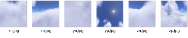
SOIL_ load_ OGL_ The order of image data passed in by the cubemap() function is:
xp,xn,yp,yn,zp,zn.
This order affects which side the cube is attached to. The following is soil2 H notes in the source code:
/**
	Loads 6 images from disk into an OpenGL cubemap texture.
	\param x_pos_file the name of the file to upload as the +x cube face
	\param x_neg_file the name of the file to upload as the -x cube face
	\param y_pos_file the name of the file to upload as the +y cube face
	\param y_neg_file the name of the file to upload as the -y cube face
	\param z_pos_file the name of the file to upload as the +z cube face
	\param z_neg_file the name of the file to upload as the -z cube face
	\param force_channels 0-image format, 1-luminous, 2-luminous/alpha, 3-RGB, 4-RGBA
	\param reuse_texture_ID 0-generate a new texture ID, otherwise reuse the texture ID (overwriting the old texture)
	\param flags can be any of SOIL_FLAG_POWER_OF_TWO | SOIL_FLAG_MIPMAPS | SOIL_FLAG_TEXTURE_REPEATS | SOIL_FLAG_MULTIPLY_ALPHA | SOIL_FLAG_INVERT_Y | SOIL_FLAG_COMPRESS_TO_DXT | SOIL_FLAG_DDS_LOAD_DIRECT
	\return 0-failed, otherwise returns the OpenGL texture handle
**/
unsigned int
	SOIL_load_OGL_cubemap
	(
		const char *x_pos_file,
		const char *x_neg_file,
		const char *y_pos_file,
		const char *y_neg_file,
		const char *z_pos_file,
		const char *z_neg_file,
		int force_channels,
		unsigned int reuse_texture_ID,
		unsigned int flags
	);

Compare it with what we used before SOIL_load_OGL_texture,The last few parameters are the same
unsigned int
	SOIL_load_OGL_texture
	(
		const char *filename,
		int force_channels,
		unsigned int reuse_texture_ID,
		unsigned int flags
	);
xp: positive x, towards the map on the + X plane;
xn: negative x, towards the map on the - x plane;
yp: positive y, towards the map on the + y plane;
yn: negative y, towards the map on the - y plane;
zp: positive z, towards the map on the + z plane;
zn: negative z, towards the map on the - z plane.
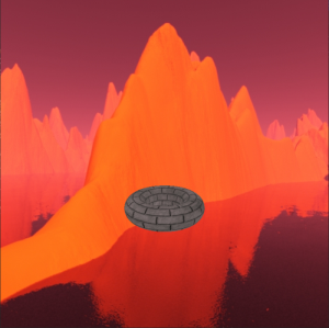
The operation effect is as follows:
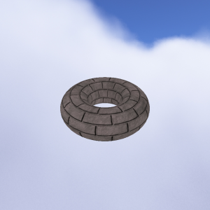
From the renderings, we see Zn Part of JPG image, and Zn Jpg is a plane in the - z direction, so what you see from the camera in the - z direction is Zn Jpg this map.
Environment map
We have never modeled very shiny objects, such as mirrors or chrome products. These objects not only have a small range of specular highlights, but also can reflect the mirror image of surrounding objects. When we look at these objects, we will see other things in the room, and sometimes even our own reflection. ADS lighting model does not provide a method to simulate this effect.
However, texture cube mapping provides a relatively simple way to simulate (at least partially simulate) reflective surfaces. The trick is to use a cube map to construct the reflective object itself.
The same technique applies to the case where the sky dome replaces the sky box by adding a sky dome texture image to a reflective object.
Using OpenGL_ TEXTURE_ CUBE_ Map), OpenGL can find the environment map in the same way as adding texture to the cube before. We use the view vector and the surface normal vector to calculate the reflection vector away from the object surface corresponding to the view vector. You can then sample the texture cube map image directly using the reflection vector. The search process is assisted by OpenGL samplerCube; Recall that the samplerCube uses the view direction vector index. Therefore, the reflection vector is very suitable for finding the required texture elements.
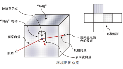
For normal vector and reflection vector, in the previous code, they are used to implement ADS lighting model; Here, they are used to calculate the texture coordinates of the environment map. So they are used for completely different purposes.
void display(GLFWwindow* window, double currentTime) {
	// The code used to draw the cube map remains unchanged
	. . .
	// All changes are in the part where the torus is drawn
	glUseProgram(renderingProgram);
	// The unified variable position of matrix transformation, including the transformation of normal vector
	mvLloc = glGetUniformLocation(renderingProgram, "mv_matrix");
	projLoc = glGetUniformLocation(renderingProgram, "proj_matrix");
	nLoc = glGetUniformLocation(renderingProgram, "norm_matrix");
	// Build the MODEL matrix, as before
	mMat = glm::translate(glm::mat4(1.0f), glm::vec3(torLocX, torLocY, torLocZ));
	// Build the MODEL-VIEW matrix, as before
	mvMat = vMat * mMat;
	invTrMat = glm::transpose(glm::inverse(mvMat));
	// The normal transformation is now in the unified variable
	glUniformMatrix4fv(mvLoc, 1, GL_FALSE, glm::value_ptr(mvMat));
	glUniformMatrix4fv(projLoc, 1, GL_FALSE, glm::value_ptr(pMat));
	glUniformMatrix4fv(nLoc, 1, GL_FALSE, glm::value_ptr(invTrMat));
	// Activate torus vertex buffer, as before
	glBindBuffer(GL_ARRAY_BUFFER, vbo[1]);
	glVertexAttribPointer(0, 3, GL_FLOAT, GL_FALSE, 0, 0);
	glEnableVertexAttribArray(0);
	// We need to activate the torus normal buffer
	glBindBuffer(GL_ARRAY_BUFFER, vbo[2]);
	glVertexAttribPointer(1, 3, GL_FLOAT, GL_FALSE, 0, 0);
	glEnableVertexAttribArray(1);
	// The torus texture is now a cube map
	glActiveTexture(GL_TEXTURE0);
	glBindTexture(GL_TEXTURE_CUBE_MAP, skyboxTexture);
	// The process of drawing the torus has not changed
	glClear(GL_DEPTH_BUFFER_BIT);
	glEnable(GL_CULL_FACE);
	glFrontFace(GL_CCW);
	glDepthFunc(GL_LEQUAL);
	glBindBuffer(GL_ELEMENT_ARRAY_BUFFER, vbo[3]);
	glDrawElements(GL_TRIANGLES, numTorusIndices, GL_UNSIGNED_INT, 0);
}
// Vertex Shader
#version 430
layout(location = 0) in vec3 position;
layout(location = 1) in vec3 normal;
out vec3 varyingNormal;
out vec3 varyingVertPos;
uniform mat4 mv_matrix;
uniform mat4 proj_matrix;
uniform mat4 norm_matrix;
void main(void) {
	varyingVertPos = (mv_matrix * vec4(position, 1.0)).xyz;
	varyingNormal = (norm_matrix * vec4(normal, 1.0)).xyz;
	gl_Position = proj_matrix * mv_matrix * vec4(position, 1.0);
}

// Fragment Shader
#version 430
in vec3 varyingVertPos;
in vec3 varyingNormal;
out vec4 fragColor;
layout(binding = 0) uniform samplerCube tex_map;
void main(void) {
	vec3 r = -reflect(normalize(-varyingVertPos), normalize(varyingNormal));
	fragColor = texture(tex_map, r);
}
The operation effect is as follows:
Retrieve the output color from the texture (now a cube map) and find it using reflection vectors instead of texture coordinates. The second parameter of texture() was vec2, but now it is vec3.
In this example, we will even feel that there seems to be a specular highlight at the lower left of the torus because of the cube
The map includes the reflection of the sun in the water.
About the reflect function
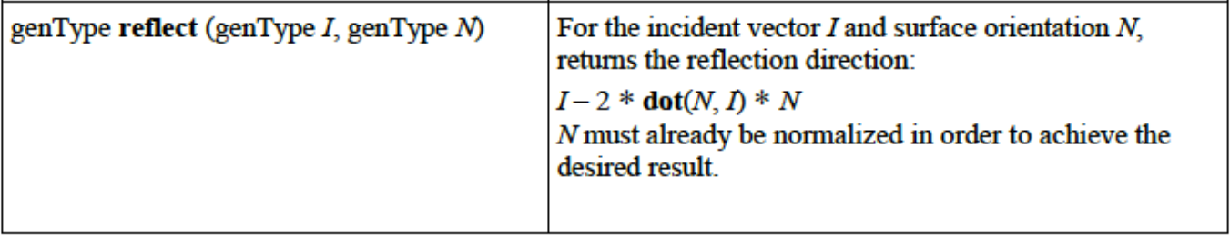
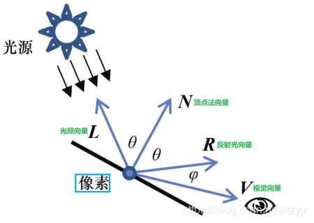
The first parameter is the incident light vector, and the second parameter is (and must be) the normalized surface normal vector.
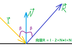
Through the knowledge of plane geometry, it is easy to deduce R = I - 2 × N●I × N.
Since | N|=1 and I is normalized in our example, there are:
R = I - 2 × cos α× N( α Is the angle between vector I and normal vector n, not the angle in the figure above β)
If α= 180 °, i.e. I is opposite to N, then R = -I, i.e. all the vertically incident light will be reflected in the opposite direction of the incident light.
If α= 90 °, R = I, i.e. the reflected light is equal to the incident light.
If α= 0 °, that is, I and N are in the same direction, then R = -I, that is, all the light parallel to the normal vector is reflected in the opposite direction of the incident light.
|R| = |I - 2 × cos α× N| != | Therefore, the size of the reflected light vector is not equal to the size of the incident light, and this inequality has nothing to do with the normalized incident light, that is, when the incident light vector is normalized, the size of the reflected light vector is not equal to 1. But its size and direction can be calculated by formula. However, it is certain that the two in the above figure β The angles are the same, but vector n is not the angular bisector of vector I and vector R. in fact, the surface plane is their angular bisector.
We have the above figure in the Blog "✠ OpenGL-7-lighting", and the GLSL code uses the following code to calculate the reflected light:
// The reflected light vector based on the surface normal vector N is calculated and normalized
vec3 R = normalize(reflect(-L, N));
ADS model has the following code for vertex shader:
// Calculates the light vector in camera space (pointing from a vertex in camera space to a light source in camera space)
varyingLightDir = light.position - varyingVertPos;
There is no light source here, so we have customized a reflection method:
vec3 r = -reflect(normalize(-varyingVertPos), normalize(varyingNormal));
The visual representation of the example code is shown as the - R vector in the following figure:
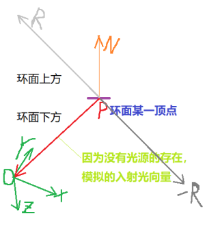
As can be seen from the figure, the color of the reflective material at the point above the torus is obtained from the sky box map below the torus.
If such a sentence is added: r = r × 1000000F; Or r = r × 0.000001F; The operation process is as like as two peas. That is to say, through vector search, it should be the material of the surface that vector rays can pass through.
If vec3 r = -reflect(...); Remove the negative sign in front, and the effect will be different, as shown in the following figure:
Obviously, there is no effect of reflection.
One of the main limitations of the environment map is that it can only build objects that reflect the contents of the cube map.
Other objects rendered in the scene do not appear in objects that use maps to simulate reflection. Whether this restriction is acceptable depends on the nature of the scene. If there are objects in the scene that must appear in specular or chrome objects, you must use other methods. A common approach is to use template buffers. The template buffer is the third buffer accessed through OpenGL -- after the color buffer and the Z buffer. This topic will not be covered.
Supplementary notes
You can also instantiate and load OpenGL cube maps without SOIL2. Although this topic will not be covered, the basic steps are as follows:
(1) Use C + + tools to read 6 image files (they must be square);
(2) Use glGenTextures() to create textures and integer references for cube maps;
(3) Call glBindTexture() to specify the ID and GL of the texture_ TEXTURE_ CUBE_ MAP;
(4) Use glTexStorage2D() to specify the storage requirements of the cube map;
(5) Call glTexImage2D() or glTexSubImage2D() to assign the image to the faces of the cube.
We did not introduce the implementation of sky dome. Although they are simpler than sky box in some aspects and are not vulnerable to distortion, and even it is simpler to use it to implement environment mapping - at least mathematically - OpenGL's support for cube mapping often makes sky box more practical.
We only briefly introduced some possible problems (such as seams), but depending on the texture image file used, other problems may occur and need to be repaired. Especially in an animated scene or when the camera can move interactively.
There are many excellent tools for generating usable and convincing texture cube map images, among which Terragen is the most popular. All cube maps in this article are made using Terragen.