Before entering the topic, you need the following knowledge:
1. Graphics rendering pipeline
The graphics rendering pipeline can be divided into two main parts: the first part converts your 3D coordinates into 2D coordinates, and the second part converts 2D coordinates into actual colored pixels.
In OpenGL, everything is in 3D space, while the screen and window are 2D pixel arrays, which makes most of OpenGL's work about transforming 3D coordinates into 2D pixels suitable for your screen. The process of converting 3D coordinates to 2D coordinates is managed by the Graphics Pipeline of OpenGL (in fact, it refers to the process that a pile of original graphics data passes through a transmission pipeline and finally appears on the screen after various change processing).
2. Shader
The graphics rendering pipeline accepts a set of 3D coordinates and converts them into colored 2D pixel output on your screen. The graphics rendering pipeline can be divided into several stages, and each stage will take the output of the previous stage as input. All of these phases are highly specialized (they all have a specific function) and are easy to execute in parallel. Because of their parallel execution characteristics, most graphics cards today have thousands of small processing cores. They run their own small programs for each (rendering pipeline) stage on the GPU, so as to quickly process your data in the graphics rendering pipeline. These applets are called shaders.
three The general steps of drawing an image by graphics rendering pipeline (the blue part represents: we can customize the functions of shaders)
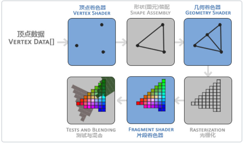
The first part of the graphics rendering pipeline is the vertex shader, which takes a single vertex as input. The main purpose of vertex shader is to convert 3D coordinates to another kind of 3D coordinates. At the same time, vertex shader allows us to do some basic processing on vertex attributes.
In the primitive assembly stage, all vertices output by the vertex shader are used as input (if it is GL_POINTS, it is a vertex), and all points are assembled into the shape of the specified primitive; The example in this section is a triangle.
The output of the element assembly phase is passed to the geometry shader. Geometry shader takes a set of vertices in the form of primitives as input. It can generate new (or other) primitives to generate other shapes by generating new vertices. In the example, it generates another triangle.
The output of the geometry shader is passed into the rasterization stage, where it maps the entities to the corresponding pixels on the final screen and generates fragments for the fragment shader. Clipping is performed before the clip shader runs. Cropping discards all pixels beyond your view to improve execution efficiency.
The main purpose of fragment shader is to calculate the final color of a pixel, which is where all OpenGL advanced effects are produced. Generally, fragment shaders contain data of 3D scene (such as lighting, shadow, light color, etc.), which can be used to calculate the color of final pixels.
After all corresponding color values are determined, the final object will be transferred to the last stage, which is called alpha testing and blending. At this stage, the corresponding depth (and Stencil) values of the segment (which will be described later) are detected to judge whether the pixel is in front of or behind other objects and decide whether it should be discarded. This phase also checks the alpha value (which defines the transparency of an object) and blends the object. Therefore, even if the output color of one pixel is calculated in the fragment shader, the final pixel color may be completely different when rendering multiple triangles.
Get to the point
#include <glad/glad.h>
#include <GLFW/glfw3.h>

#include <iostream>


void framebuffer_size_callback(GLFWwindow* window, int width, int height);


void processInput(GLFWwindow* window);


int main() {

	glfwInit();


	glfwWindowHint(GLFW_CONTEXT_VERSION_MAJOR, 3);
	glfwWindowHint(GLFW_CONTEXT_VERSION_MINOR, 3);
	glfwWindowHint(GLFW_OPENGL_PROFILE, GLFW_OPENGL_CORE_PROFILE);


	GLFWwindow* window = glfwCreateWindow(800, 600, "LearnOpenGL", NULL, NULL);
	if (window == NULL) {
		std::cout << "Failed to open window" << std::endl;
		glfwTerminate();
		return -1;
	}

	glfwMakeContextCurrent(window);

	glfwSetFramebufferSizeCallback(window, framebuffer_size_callback);

	if (!gladLoadGLLoader((GLADloadproc)glfwGetProcAddress))
	{
		std::cout << "initialization GLAD Library failed" << std::endl;
		return -1;
	}

	//Custom vertex shader
	const char* vertexShaderSource = "#version 330 core\n"
		"layout (location = 0) in vec3 aPos;\n"
		"void main()\n"
		"{\n"
		"   gl_Position = vec4(aPos.x, aPos.y, aPos.z, 1.0);\n"
		"}\0";


	//Create a shader object. Note that it is still referenced by ID. So we store this vertex shader as unsigned int
	//	 Then create this shader with glCreateShader:
	unsigned int vertexShader;
	vertexShader = glCreateShader(GL_VERTEX_SHADER);
	//We provide the shader type to be created to glCreateShader as a parameter.
	//	Since we are creating a vertex shader, the parameter passed is GL_VERTEX_SHADER.


	//Next, we attach the shader source code to the shader object and compile it:
	glShaderSource(vertexShader, 1, &vertexShaderSource, NULL);
	glCompileShader(vertexShader);
	//The glShaderSource function takes the shader object to be compiled as the first parameter.
	//	The second parameter specifies the number of source strings passed. There is only one. The third parameter is the real source code of vertex shader,
	//	The fourth parameter is set to NULL first.

	//Check whether glCompileShader compilation is successful
	int  success;
	char infoLog[512];
	glGetShaderiv(vertexShader, GL_COMPILE_STATUS, &success);
	if (!success)
	{
		glGetShaderInfoLog(vertexShader, 512, NULL, infoLog);
		std::cout << "ERROR::SHADER::VERTEX::COMPILATION_FAILED\n" << infoLog << std::endl;
	}


	//Custom clip shader
	const char* fragmentShaderSource = "#version 330 core\n"
		"out vec4 FragColor;\n"
		"void main()\n"
		"{\n"
		"   FragColor = vec4(1.0f, 0.5f, 0.2f, 1.0f);\n"
		"}\n\0";

	//As with fixed-point shaders, to create an object, you need to bind it
	//	It's just that we use GL_FRAGMENT_SHADER constant as shader type:
	unsigned int fragmentShader;
	fragmentShader = glCreateShader(GL_FRAGMENT_SHADER);
	glShaderSource(fragmentShader, 1, &fragmentShaderSource, NULL);
	glCompileShader(fragmentShader);

	//Check whether glCompileShader compilation is successful
	glGetShaderiv(vertexShader, GL_COMPILE_STATUS, &success);
	if (!success)
	{
		glGetShaderInfoLog(vertexShader, 512, NULL, infoLog);
		std::cout << "ERROR::SHADER::FRAGMENT::COMPILATION_FAILED\n" << infoLog << std::endl;
	}


	//Both shaders are now compiled, and the rest is to link the two shader objects to a shader program for rendering.
	//create object
	unsigned int shaderProgram;
	shaderProgram = glCreateProgram();
	//The glCreateProgram function creates a program and returns the ID reference of the newly created program object.
	//	Now we need to attach the previously compiled shaders to the program objects and link them with glLinkProgram:
	glAttachShader(shaderProgram, vertexShader);
	glAttachShader(shaderProgram, fragmentShader);
	glLinkProgram(shaderProgram);

	//Detects whether the connection shader is successful
	glGetProgramiv(shaderProgram, GL_LINK_STATUS, &success);
	if (!success) {
		glGetProgramInfoLog(shaderProgram, 512, NULL, infoLog);
		std::cout << "ERROR::SHADER::PROGRAM::LINKING_FAILED\n" << infoLog << std::endl;
	}

	//The result is a program object. We can call the glUseProgram function,
	//	Use the newly created program object as its parameter to activate this program object:
	//	glUseProgram(shaderProgram); (you don't need to activate it yet)

	//After the glUseProgram function call, each shader call and rendering call will use the program object (that is, the shader written before).
	//	By the way, after linking shader objects to program objects, remember to delete shader objects. We don't need them anymore:
	glDeleteShader(vertexShader);
	glDeleteShader(fragmentShader);


	//The vertex shader allows us to specify any input in the form of vertex attributes, which makes it very flexible,
	//	It does also mean that we must manually specify which part of the input data corresponds to which vertex attribute of the vertex shader.
	//	Therefore, we must specify how OpenGL interprets vertex data before rendering.
	glVertexAttribPointer(0, 3, GL_FLOAT, GL_FALSE, 3 * sizeof(float), (void*)0);
	glEnableVertexAttribArray(0);
	//Arguments to the glVertexAttribPointer function
	//	The first parameter specifies the vertex attributes we want to configure. Remember that we used layout(location = 0) in the vertex shader to define the location value of the position vertex attribute?
	//			It can set the position value of vertex attribute to 0. Because we want to pass the data to this vertex attribute, we pass 0 here.
	//	The second parameter specifies the size of the vertex attribute. The vertex attribute is a vec3, which consists of three values, so the size is 3.
	//	The third parameter specifies the type of data. Here is GL_ Float (vec * in glsl is composed of floating-point values).
	//	The fourth parameter defines whether we want the data to be normalized.
	//			If we set it to GL_ If true, all data will be mapped between 0 (or - 1 for signed data) and 1. We set it to GL_FALSE.
	//	The fifth parameter is called step, which tells us the interval between successive vertex attribute groups.
	//			We can also set it to 0 to let OpenGL determine the specific step size (available only when the values are closely arranged).
	//	The type of the last parameter is void *, so we need to do this strange cast. It represents the offset of the starting position of the position data in the buffer.
	//			Since the position data is at the beginning of the array, here is 0.


	//triangle
	float vertices[] = {
		-0.5f, -0.5f, 0.0f,//lower left quarter
		 0.5f, -0.5f, 0.0f,//Lower right corner
		 0.0f,  0.5f, 0.0f//Apex angle
	};//x,y,z coordinates

	unsigned int VBO, VAO;
	glGenVertexArrays(1, &VAO);//Array to hold unused drawn objects
	glGenBuffers(1, &VBO);//Generate a VBO object using the glGenBuffers function and a buffer ID:

	// 1. Bind VAO
	glBindVertexArray(VAO);
	// 2. Copy the vertex array to the buffer for OpenGL
	//		OpenGL has many buffer object types, and the buffer type of vertex buffer object is GL_ARRAY_BUFFER.
	//		OpenGL allows us to bind multiple buffers at the same time, as long as they are different buffer types.
	glBindBuffer(GL_ARRAY_BUFFER, VBO);
	//		From this point on, any buffer call we use (on the GL_ARRAY_BUFFER target) will be used to configure the currently bound buffer (VBO).
	//		Then we can call the glBufferData function, which will copy the previously defined vertex data into the buffered memory:
	glBufferData(GL_ARRAY_BUFFER, sizeof(vertices), vertices, GL_STATIC_DRAW);
															//GL_STATIC_DRAW: the data will not or will hardly change.
															//GL_DYNAMIC_DRAW: the data will be changed a lot.
															//GL_STREAM_DRAW: data changes every time it is drawn.

	// 3. Set vertex attribute pointer
	glVertexAttribPointer(0, 3, GL_FLOAT, GL_FALSE, 3 * sizeof(float), (void*)0);
	glEnableVertexAttribArray(0);

	glBindBuffer(GL_ARRAY_BUFFER, 0);

	glBindVertexArray(0);


	while (!glfwWindowShouldClose(window)) {

		processInput(window);

		glClearColor(0.2f, 0.3f, 0.3f, 1.0f);
		glClear(GL_COLOR_BUFFER_BIT);

		// 4. Draw objects
		//OpenGL provides us with the glDrawArrays function, which uses the currently active shader,
		//	The previously defined vertex attribute configuration, and VBO vertex data (indirectly bound through VAO) to draw entities.
		glUseProgram(shaderProgram);
		glBindVertexArray(VAO);
		glDrawArrays(GL_TRIANGLES, 0, 3);


		glfwSwapBuffers(window);
		glfwPollEvents();

	}

	//5. After drawing, liberate resources
	glDeleteVertexArrays(1, &VAO);
	glDeleteBuffers(1, &VBO);
	glDeleteProgram(shaderProgram);


	glfwTerminate();


	return 0;
}


void framebuffer_size_callback(GLFWwindow* window, int width, int height) {
	glViewport(0, 0, width, height);
}

void processInput(GLFWwindow* window) {
	if (glfwGetKey(window, GLFW_KEY_ESCAPE) == GLFW_PRESS)
		glfwSetWindowShouldClose(window, true);
}