Network topology
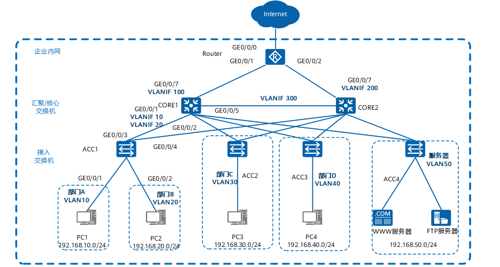
- The core switch is configured with VRRP to ensure network reliability, load sharing and effective utilization of resources.
- The services of each department are divided into a VLAN, and the services between departments are interconnected through VLANIF three layers on the CORE.
- As a DHCP Server, the core switch assigns IP addresses to users in the park.
- DHCP Snooping function is configured on the access switch to prevent intranet users from privately connecting to the small router to allocate IP address; At the same time, the IP message check function is configured to prevent intranet users from changing the IP address without permission.

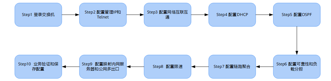
network configuration
Manage IP and Telnet
Configure the management IP address.
<HUAWEI> system-view
[HUAWEI] vlan 5               //Create switch management VLAN 5
[HUAWEI-VLAN5] management-vlan
[HUAWEI-VLAN5] quit
[HUAWEI] interface vlanif 5       //Create VLANIF interface for switch management VLAN
[HUAWEI-vlanif5] ip address 10.10.1.1 24   //Configure VLANIF interface IP address
[HUAWEI-vlanif5] quit
Add the management interface to the management VLAN.
[HUAWEI] interface GigabitEthernet 0/0/8       //It is assumed that the interface connecting the network management is GigabitEthernet 0/0/8
[HUAWEI-GigabitEthernet0/0/8] port link-type trunk
[HUAWEI-GigabitEthernet0/0/8] port trunk allow-pass vlan 5
[HUAWEI-GigabitEthernet0/0/8] quit
Configure Telnet.
[HUAWEI] telnet server enable     //Telnet is turned off at the factory and needs to be turned on
[HUAWEI] user-interface vty 0 4    //Telnet is commonly used for device administrator login, and AAA Authentication is recommended
[HUAWEI-ui-vty0-4] protocol inbound telnet  // V200R006 and earlier versions support telnet protocol by default, but V200R007 and later versions default to SSH protocol. Therefore, this command must be configured before telnet login.
[HUAWEI-ui-vty0-4] authentication-mode aaa
[HUAWEI-ui-vty0-4] idle-timeout 15
[HUAWEI-ui-vty0-4] quit
[HUAWEI] aaa
[HUAWEI-aaa] local-user admin password irreversible-cipher Helloworld@6789   //Configure the user name and password of the administrator Telnet login switch. The user name is case insensitive, and the password is case sensitive
[HUAWEI-aaa] local-user admin privilege level 15        //Set the administrator's account permission to 15 (maximum)
[HUAWEI-aaa] local-user admin service-type telnet
[HUAWEI-aaa] quit
Configure network interworking
Configure access layer switch
Taking access switch ACC1 as an example, create service VLANs 10 and 20 of ACC1.
<HUAWEI> system-view
[HUAWEI] sysname ACC1              //Modify the device name to ACC1
[ACC1] vlan batch 10 20           //Create VLAN s in batch
Configure ACC1 to connect GE0/0/3 and GE0/0/4 of CORE1 and CORE2, and transparently transmit VLAN s of department A and department B.
[ACC1] interface GigabitEthernet 0/0/3
[ACC1-GigabitEthernet0/0/3] port link-type trunk   //It is configured as trunk mode for transparent VLAN transmission.
[ACC1-GigabitEthernet0/0/3] port trunk allow-pass vlan 10 20 //Configure the service VLAN on GE0/0/3 transparent transmission ACC1
[ACC1-GigabitEthernet0/0/3] quit
[ACC1] interface GigabitEthernet 0/0/4
[ACC1-GigabitEthernet0/0/4] port link-type trunk   //It is configured as trunk mode for transparent VLAN transmission.
[ACC1-GigabitEthernet0/0/4] port trunk allow-pass vlan 10 20 //Configure the service VLAN on GE0/0/4 transparent transmission ACC1
[ACC1-GigabitEthernet0/0/4] quit
Configure the interface of ACC1 connecting users to enable each department to join VLAN.
[ACC1] interface GigabitEthernet 0/0/1           //Configure the interface connecting Department A
[ACC1-GigabitEthernet0/0/1] port link-type access
[ACC1-GigabitEthernet0/0/1] port default vlan 10
[ACC1-GigabitEthernet0/0/1] quit
[ACC1] interface GigabitEthernet 0/0/2           //Configure the interface connecting Department B
[ACC1-GigabitEthernet0/0/2] port link-type access
[ACC1-GigabitEthernet0/0/2] port default vlan 20
[ACC1-GigabitEthernet0/0/2] quit
Configure BPDU protection function to strengthen the stability of the network.
[ACC1] stp bpdu-protection
Configure aggregation / core layer switches
Take the aggregation / core switch CORE1 as an example to create VLAN s that interweave with access switches, backup equipment and exit routers in the park.
<HUAWEI> system-view
[HUAWEI] sysname CORE1                            //Modify the device name to CORE1
[CORE1] vlan batch 10 20 30 40 50 100 300        //Create VLAN s in batch
Configure VLAN and VLANIF interfaces on the user side. VLANIF interfaces are used for mutual visits between departments. Take the GE0/0/1 interface of CORE1 connected to ACC1 as an example, and other interfaces will not be described again.
[CORE1] interface GigabitEthernet 0/0/1
[CORE1-GigabitEthernet0/0/1] port link-type trunk    //It is configured as trunk mode for transparent VLAN transmission
[CORE1-GigabitEthernet0/0/1] port trunk allow-pass vlan 10 20  //Configure the service VLAN on GE0/0/1 transparent transmission ACC1
[CORE1-GigabitEthernet0/0/1] quit
[CORE1] interface Vlanif 10                //VLANIF10 is configured to enable three-layer interworking between departments
[CORE1-Vlanif10] ip address 192.168.10.1 24
[CORE1-Vlanif10] quit
[CORE1] interface Vlanif 20                //VLANIF20 is configured to enable three-layer interworking between departments
[CORE1-Vlanif20] ip address 192.168.20.1 24
[CORE1-Vlanif20] quit
Configure the interface VLAN and VLANIF connecting the exit router.
[CORE1] interface GigabitEthernet 0/0/7
[CORE1-GigabitEthernet0/0/7] port link-type access     //Configure to access mode
[CORE1-GigabitEthernet0/0/7] port default vlan 100
[CORE1-GigabitEthernet0/0/7] quit
[CORE1] interface Vlanif 100            //Configure VLANIF to enable layer 3 interworking between CORE1 and router
[CORE1-Vlanif100] ip address 172.16.1.1 24
[CORE1-Vlanif100] quit
Configure the interface VLAN and VLANIF directly connected to two core switches.
[CORE1] interface gigabitethernet 0/0/5
[CORE1-GigabitEthernet0/0/5] port link-type access      //Configure to access mode
[CORE1-GigabitEthernet0/0/5] port default vlan 300
[CORE1-GigabitEthernet0/0/5] quit
[CORE1] interface Vlanif 300
[CORE1-Vlanif300] ip address 172.16.3.1 24
[CORE1-Vlanif300] quit
Configure the interface address of the exit router
Configure the address of the interface connecting to the intranet.
<HUAWEI> system-view
[HUAWEI] sysname Router                           //Modify the equipment name to Router
[Router] interface GigabitEthernet 0/0/1
[Router-GigabitEthernet0/0/1] ip address 172.16.1.2 24  //Configure the interface address to interconnect with the master
[Router-GigabitEthernet0/0/1] quit
[Router] interface GigabitEthernet 0/0/2
[Router-GigabitEthernet0/0/2] ip address 172.16.2.2 24  //Configure the interface address for interconnection with the standby device
[Router-GigabitEthernet0/0/2] quit
Configure the address of the interface connecting to the public network.
[Router] interface GigabitEthernet 0/0/0
[Router-GigabitEthernet0/0/0] ip address 1.1.1.2 30   //Configure the interface address of the router to connect to the public network
[Router-GigabitEthernet0/0/0] quit
Static routing
Configure a default static route on CORE1 and CORE2 respectively to point to the exit router and its backup route.
[CORE1] ip route-static 0.0.0.0 0.0.0.0 172.16.1.2   //CORE1 is the default static route to the exit router
[CORE1] ip route-static 0.0.0.0 0.0.0.0 172.16.3.2 preference 70   //Backup static route from CORE1 to CORE2
[CORE2] ip route-static 0.0.0.0 0.0.0.0 172.16.2.2
[CORE2] ip route-static 0.0.0.0 0.0.0.0 172.16.3.1 preference 70
Configure a default static route in the exit router to point to the operator
[Router] ip route-static 0.0.0.0 0.0.0.0 1.1.1.1
Configure the primary and standby routes from the exit router to the intranet. The next hop of the primary route points to CORE1 and the next hop of the standby route points to CORE2.
[Router] ip route-static 192.168.10.0 255.255.255.0 172.16.1.1
[Router] ip route-static 192.168.10.0 255.255.255.0 172.16.2.1 preference 70  //Configure the backup route to the backup device from the VLAN10 network segment
[Router] ip route-static 192.168.20.0 255.255.255.0 172.16.1.1
[Router] ip route-static 192.168.20.0 255.255.255.0 172.16.2.1 preference 70  //Configure the backup route to the backup device from the VLAN20 network segment
Configure VRRP active and standby backup to realize virtual gateway redundancy
Under normal circumstances, the intranet user traffic is sent to CORE1 for processing. Only when CORE1 fails, the VRRP backup group switches CORE2 to the main device, and the intranet user traffic is sent to CORE2.
Configuration example: create VRRP backup groups 1 and 2 on CORE1 and CORE2. Configure CORE1 with priority of 120 and preemption delay of 20 seconds as Master devices of VLAN10 and VLAN20
[CORE1] interface Vlanif 10
[CORE1-Vlanif10] vrrp vrid 1 virtual-ip 192.168.10.3    //Configure the virtual address of VRRP group 1
[CORE1-Vlanif10] vrrp vrid 1 priority 120              //The priority of CORE1 is 120
[CORE1-Vlanif10] vrrp vrid 1 preempt-mode timer delay 20
[CORE1-Vlanif10] quit
[CORE1] interface Vlanif 20
[CORE1-Vlanif20] vrrp vrid 2 virtual-ip 192.168.20.3    //Configure the virtual address of VRRP group 2
[CORE1-Vlanif20] vrrp vrid 2 priority 120
[CORE1-Vlanif20] vrrp vrid 2 preempt-mode timer delay 20
[CORE1-Vlanif20] quit
The priority of CORE2 is the default value and serves as the Backup device of VLAN10 and VLAN20.
[CORE2] interface Vlanif 10
[CORE2-Vlanif10] vrrp vrid 1 virtual-ip 192.168.10.3
[CORE2-Vlanif10] quit
[CORE2] interface Vlanif 20
[CORE2-Vlanif20] vrrp vrid 2 virtual-ip 192.168.20.3
[CORE2-Vlanif20] quit
Because CORE1, CORE2 and ACC1 are physically looped, the actual link is not looped, while X7 series switches enable stp function by default. In order to avoid affecting the status of VRRP active / standby backup between CORE1 and CORE2, it is necessary to turn off the stp function of the access switch connecting the uplink interface. The specific configuration commands are as follows:
[ACC1] interface GigabitEthernet 0/0/3
[ACC1-GigabitEthernet0/0/3] stp disable     //Configure and turn off the stp function of ACC1 uplink interface
[ACC1-GigabitEthernet0/0/3] quit
[ACC1] interface GigabitEthernet 0/0/4
[ACC1-GigabitEthernet0/0/4] stp disable
[ACC1-GigabitEthernet0/0/4] quit
If you ensure that there is no loop in the network, you can also directly turn off the stp function of the whole machine. The configuration command is as follows:
[ACC1] stp disable
Warning:The global STP state will be changed. Continue? [Y/N] y
Configure exit router to realize intranet sharing and Internet access
Configure ACL S that allow Internet access. Take VLAN 10 and 20 users as an example:
[Router] acl 2000
[Router-acl-basic-2000] rule permit source 192.168.10.0 0.0.0.255    //Configure to allow VLAN 10 users to access the Internet
[Router-acl-basic-2000] rule permit source 192.168.20.0 0.0.0.255   //Configure to allow VLAN 20 users to access the Internet
[Router-acl-basic-2000] rule permit source 172.16.1.0 0.0.0.255
[Router-acl-basic-2000] rule permit source 172.16.2.0 0.0.0.255
[Router-acl-basic-2000] quit
NAT conversion is configured at the interface connected to the public network to realize intranet access.
[Router] interface GigabitEthernet 0/0/0
[Router-GigabitEthernet0/0/0] nat outbound 2000
[Router-GigabitEthernet0/0/0] quit
Configure the DNS address resolution function. The DNS server address is specified by the operator.
[Router] dns resolve
[Router] dns server 8.8.8.8
[Router] dns proxy enable
After completing the above configuration, configure the static address for the users of Intranet VLAN 10, and set the gateway to 192.168.10.3 to access the Internet.
Configure DHCP
Configure DHCP server
The network administrator configures a fixed IP address for each terminal. When the network scale gradually increases, manually configuring the address for the terminal becomes cumbersome and difficult to manage. In order to reduce the management burden, the administrator decides that all end users will automatically obtain the address from the DHCP server, except for individual terminals that must have a fixed address.
Configure the core switch as the DHCP Server so that users in all departments can dynamically obtain the correct IP address. The following describes the configuration steps of DHCP Server by taking CORE1 as the main DHCP Server and taking department A as an example.
Note: This paper takes the DHCP Server based on the global address pool as an example. In the VRRP networking environment, in order to prevent the IP address conflict caused by the primary and standby switching, when configuring the DHCP Server, the primary device allocates the first half of the address segment and the standby device allocates the second half of the address segment.
Configure CORE1 as the primary DHCP server and allocate the first half of the address segment.
<CORE1> system-view
[CORE1] dhcp enable
[CORE1] ip pool 10
[CORE1-ip-pool-10] gateway-list 192.168.10.3         //Configure gateway address
[CORE1-ip-pool-10] network 192.168.10.0 mask 24      //Configure assignable IP address range
[CORE1-ip-pool-10] excluded-ip-address 192.168.10.128 192.168.10.254  //Configure the second half of the excluded address segment
[CORE1-ip-pool-10] lease day 0 hour 20 minute 0      //Configure lease term
[CORE1-ip-pool-10] dns-list 8.8.8.8         //Configure DNS server address
[CORE1-ip-pool-10] quit
Configure CORE2 as the standby DHCP server and allocate the second half of the address segment.
<CORE2> system-view
[CORE2] dhcp enable
[CORE2] ip pool 10
[CORE2-ip-pool-10] gateway-list 192.168.10.3
[CORE2-ip-pool-10] network 192.168.10.0 mask 24
[CORE2-ip-pool-10] excluded-ip-address 192.168.10.1 192.168.10.2
[CORE2-ip-pool-10] excluded-ip-address 192.168.10.4 192.168.10.127
[CORE2-ip-pool-10] lease day 0 hour 20 minute 0
[CORE2-ip-pool-10] dns-list 8.8.8.8
[CORE2-ip-pool-10] quit
The DHCP dynamic address allocation method for VLAN20 is the same as above.
- Configure the user of department A to obtain the IP address from the global address pool.
[CORE1] interface vlanif 10
[CORE1-Vlanif10] dhcp select global      //Configure the user of department A to obtain the IP address from the global address pool
[CORE1-Vlanif10] quit
[CORE2] interface vlanif 10
[CORE2-Vlanif10] dhcp select global
[CORE2-Vlanif10] quit
-
Use the display ip pool command to view the configuration and usage of the global address pool 10.
-
After the DHCP server is configured, the network card of the terminal computer needs to be set to automatically obtain the address, so that the terminal can normally obtain the address from the DHCP server and surf the Internet normally.
-
After the dynamic address allocation is configured, it takes a long time to start the computer to obtain the address. This is because for the switch with the spanning tree protocol turned on, it takes a long time to recalculate and converge the spanning tree whenever a computer is connected; It can be solved by closing the spanning tree protocol of the interface or configuring the switch interface connecting the terminal as an edge port.
Close the spanning tree protocol of the interface
[ACC1] interface GigabitEthernet 0/0/1
[ACC1-GigabitEthernet 0/0/1] stp disable  //The undo stp enable command can also complete this function
[ACC1-GigabitEthernet0/0/1] quit
Configure the switch interface connecting terminal equipment as edge port
[ACC1] interface GigabitEthernet 0/0/1
[ACC1-GigabitEthernet0/0/1] stp edged-port enable
[ACC1-GigabitEthernet0/0/1] quit
Select one of the above two methods for configuration, and the problem of slow address acquisition speed can be effectively solved as soon as the terminal computer starts up.
Configure DHCP Snooping and IPSG
After the DHCP function is configured, the user host in the Department can automatically obtain the address. However, in order to prevent employees from privately connecting to a small router in the intranet and turning on the function of DHCP automatic address assignment, resulting in the legitimate users of the intranet getting the address assigned by the private small router and unable to access the Internet normally, it is also necessary to configure the DHCP Snooping function.
Taking department A as an example, the following describes the configuration process of DHCP Snooping.
Enable the DHCP Snooping function on the access switch ACC1.
<ACC1> system-view
[ACC1] dhcp enable  //Enable DHCP function
[ACC1] dhcp snooping enable //Enable DHCP Snooping function
Enable the DHCP Snooping function on the interface connecting the terminal.
[ACC1] interface GigabitEthernet 0/0/1                //Configure the interface connecting Department A
[ACC1-GigabitEthernet0/0/1] dhcp snooping enable
[ACC1-GigabitEthernet0/0/1] quit
[ACC1] interface GigabitEthernet 0/0/2                //Configure the interface connecting Department B
[ACC1-GigabitEthernet0/0/2] dhcp snooping enable
[ACC1-GigabitEthernet0/0/2] quit
Enable the DHCP Snooping function on the interface connecting to the DHCP server and configure this interface as a trust interface.
[ACC1] interface GigabitEthernet 0/0/3             //Configure the interface connecting CORE1
[ACC1-GigabitEthernet0/0/3] dhcp snooping enable    //Enable DHCP Snooping function
[ACC1-GigabitEthernet0/0/3] dhcp snooping trusted   //Configure as trusted interface
[ACC1-GigabitEthernet0/0/3] quit
[ACC1] interface GigabitEthernet 0/0/4            //Configure the interface connecting CORE2
[ACC1-GigabitEthernet0/0/4] dhcp snooping enable
[ACC1-GigabitEthernet0/0/4] dhcp snooping trusted
[ACC1-GigabitEthernet0/0/4] quit
After completing the above configuration, the users of department A can obtain the IP address from the legal DHCP server, and the address assigned by the small router privately connected to the intranet will not interfere with the normal users of the intranet.
In order to prevent users in the Department from attacking the network after changing the IP address without permission, after the access switch turns on the DHCP Snooping function, it is also necessary to turn on the IP message check function. For specific configuration, take ACC1 as an example.
Turn on the IP message check function of VLAN10 on the access switch ACC1.
[ACC1] vlan 10
[ACC1-vlan10] ip source check user-bind enable //Enable IP message check function
[ACC1-vlan10] quit
In this way, ACC1 will match the message with the entries of the dynamic binding table after receiving the message from VLAN 10, release the matched message and discard the mismatched message. If you do not want to check the messages received by the whole VLAN, you can only turn on the IP message check function on the interface connected to a terminal.
If the static allocation of IP address is adopted in the network, IP+MAC binding can be configured to prevent users from modifying the address without permission to attack the network.
OSPF configuration
Because the intranet interconnection uses static routing, the administrator needs to manually configure new static routing after link failure, resulting in long-term network interruption and affecting services. In order to reduce the occurrence of such failures, using dynamic routing protocol is a good choice. Dynamic routing has its own algorithm. After the link fails, dynamic routing switches the traffic to the normal link in time according to its own algorithm. After the fault is recovered, the traffic is switched back. The following configuration takes the dynamic routing protocol OSPF as an example:
Delete the static routing configuration of two aggregation / core switches.
[CORE1] undo ip route-static all
[CORE2] undo ip route-static all
Delete the static route from the exit router to the intranet and retain the default route to the public network.
[Router] undo ip route-static 192.168.10.0 24
[Router] undo ip route-static 192.168.20.0 24
OSPF configuration of CORE1.
[CORE1] ospf 100 router-id 2.2.2.2
[CORE1-ospf-100] area 0
[CORE1-ospf-100-area-0.0.0.0] network 172.16.1.0 0.0.0.255
[CORE1-ospf-100-area-0.0.0.0] network 172.16.3.0 0.0.0.255
[CORE1-ospf-100-area-0.0.0.0] network 192.168.10.0 0.0.0.255
[CORE1-ospf-100-area-0.0.0.0] network 192.168.20.0 0.0.0.255
[CORE1-ospf-100-area-0.0.0.0] quit
[CORE1-ospf-100] quit
OSPF configuration of CORE2.
[CORE2] ospf 100 router-id 3.3.3.3
[CORE2-ospf-100] area 0
[CORE2-ospf-100-area-0.0.0.0] network 172.16.2.0 0.0.0.255
[CORE2-ospf-100-area-0.0.0.0] network 172.16.3.0 0.0.0.255
[CORE2-ospf-100-area-0.0.0.0] network 192.168.10.0 0.0.0.255
[CORE2-ospf-100-area-0.0.0.0] network 192.168.20.0 0.0.0.255
[CORE2-ospf-100-area-0.0.0.0] quit
[CORE2-ospf-100] quit
For OSPF configuration of the exit router, in order to connect the intranet and the public network, it is necessary to configure the static default route to the public network. The default route needs to be introduced in the OSPF process, and a default static route needs to be configured to point to the operator.
[Router] ospf 100 router-id 1.1.1.1
[Router-ospf-100] default-route-advertise always
[Router-ospf-100] area 0
[Router-ospf-100-area-0.0.0.0] network 172.16.1.0 0.0.0.255
[Router-ospf-100-area-0.0.0.0] network 172.16.2.0 0.0.0.255
[Router-ospf-100-area-0.0.0.0] quit
[Router-ospf-100] quit
[Router] ip route-static 0.0.0.0 0.0.0.0 1.1.1.1
Configuration reliability and load sharing
When the link from CORE1 to the outlet router fails, the traffic will reach the outlet router through CORE2 through the interconnection link from CORE1 to CORE2. At this time, the burden of the interconnection link is increased, and the requirements for the stability and bandwidth load of the interconnection link are very high. In the current network environment, it is generally hoped that the fast switching between active and standby equipment can be realized when the uplink interface of active and standby equipment fails. This fast switching can be realized by configuring the VRRP and interface state linkage function. Configure to detect the uplink interface in the VRRP backup group. When it is detected that the interface is down, the device will realize the active / standby switching by reducing the priority.
The VRRP linkage interface monitors the uplink.
[CORE1] interface Vlanif 10
[CORE1-Vlanif10] vrrp vrid 1 track interface GigabitEthernet 0/0/7 reduced 100    //Configure VRRP and uplink interface status linkage monitoring interface function
[CORE1-Vlanif10] quit
[CORE1] interface Vlanif 20
[CORE1-Vlanif20] vrrp vrid 2 track interface GigabitEthernet 0/0/7 reduced 100
[CORE1-Vlanif20] quit
Configure load sharing
With the growth of business, the bandwidth occupation rate of the link through CORE1 is too high, but the link through CORE2 is idle, which not only has poor reliability, but also wastes resources. It is particularly important to make effective use of the left and right links. The VRRP active and standby backup is configured as load sharing. Some VLANs use CORE1 as the main device and others use CORE2 as the main device. The traffic of different VLANs is allocated to the left and right links to make effective use of the existing network resources. Here, CORE1 continues to be the master of VLAN 10, and the priority of CORE2 is modified to become the master of VLAN 20.
First, delete the priority and preemption delay configuration of VRRP backup group 2 on CORE1.
[CORE1] interface Vlanif 20
[CORE1-Vlanif20] undo vrrp vrid 2 preempt-mode timer delay
[CORE1-Vlanif20] undo vrrp vrid 2 priority
[CORE1-Vlanif20] quit
CORE2 is configured as the main device of VLAN20, and the preemption delay is 20S.
[CORE2] interface Vlanif 20
[CORE2-Vlanif20] vrrp vrid 2 priority 120
[CORE2-Vlanif20] vrrp vrid 2 preempt-mode timer delay 20
Configure the VRRP backup group linkage uplink interface to monitor the uplink.
[CORE2-Vlanif20] vrrp vrid 2 track interface GigabitEthernet 0/0/7 reduced 100
[CORE2-Vlanif20] quit
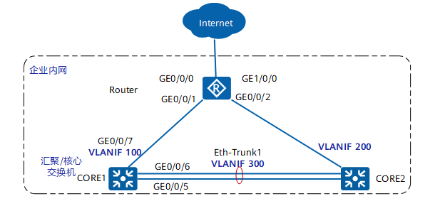
Configure link aggregation
When the uplink of CORE1 or CORE2 fails, the traffic passes through the link interconnected by CORE1 and CORE2, but a single link may have insufficient bandwidth, resulting in data loss. In order to increase the bandwidth, multiple physical links are bundled into one logical link to increase the bandwidth and improve the reliability of the link. The specific configuration is as follows:
Restore the interface default configuration (if the interface is the default configuration, please configure it directly). The steps and commands to restore the interface to the default configuration are as follows:
[CORE1] interface GigabitEthernet 0/0/5
[CORE1-GigabitEthernet0/0/5] dis this
#
interface GigabitEthernet0/0/5
 port link-type access
 port default vlan 300
#
return
[CORE1-GigabitEthernet0/0/5] undo port default vlan
[CORE1-GigabitEthernet0/0/5] undo port link-type
V200R005 and later versions can use a command to restore the interface to the initial configuration. After restoration, the interface is closed and needs to be opened manually by undo shutdown:
[CORE1-GigabitEthernet0/0/5] clear configuration this
Warning: All configurations of the interface will be cleared, and its state will be shutdown. Continue? [Y/N] :y
Info: Total 2 command(s) executed, 2 successful, 0 failed.
[CORE1-GigabitEthernet0/0/5] undo shutdown
[CORE1-GigabitEthernet0/0/5] quit
To configure link aggregation, the steps and commands are as follows:
Mode 1: configure link aggregation in manual load sharing mode
[CORE1] interface Eth-Trunk 1
[CORE1-Eth-Trunk1] trunkport GigabitEthernet 0/0/5 to 0/0/6
[CORE1-Eth-Trunk1] port link-type access
[CORE1-Eth-Trunk1] port default vlan 300
[CORE1-Eth-Trunk1] quit
Mode 2: configure link aggregation in LACP mode
[CORE1] interface Eth-Trunk 1
[CORE1-Eth-Trunk1] mode lacp
[CORE1-Eth-Trunk1] trunkport GigabitEthernet 0/0/5 to 0/0/6
[CORE1-Eth-Trunk1] port link-type access
[CORE1-Eth-Trunk1] port default vlan 300
[CORE1-Eth-Trunk1] quit
Configure the system priority of 100 on CORE1 to become the active end of LACP
[CORE1] lacp priority 100
Configure the upper limit threshold of active interface on CORE1 as 2
[CORE1] interface Eth-Trunk 1
[CORE1-Eth-Trunk1] max active-linknumber 2
[CORE1-Eth-Trunk1] quit
Configure the interface priority on CORE1 to determine the active link (configure GE0/0/5 and GE0/0/6 as active links)
[CORE1] interface GigabitEthernet 0/0/5
[CORE1-GigabitEthernet0/0/5] lacp priority 100
[CORE1-GigabitEthernet0/0/5] quit
[CORE1] interface GigabitEthernet 0/0/6
[CORE1-GigabitEthernet0/0/6] lacp priority 100
[CORE1-GigabitEthernet0/0/6] quit
The configuration of CORE2 is the same as above, except that there is no need to configure the system priority, and the default priority of the system can be used.