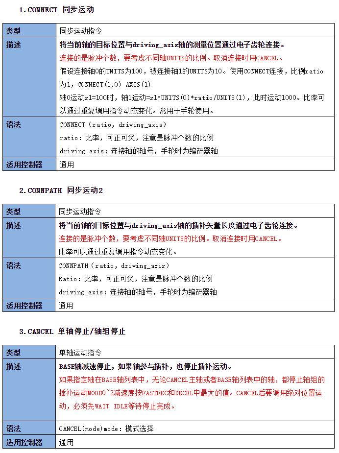
PLC programming of EtherCAT motion controller (III) electronic gear
Electronic gear mode can connect two or more shafts to achieve accurate synchronous motion, so as to replace the traditional mechanical gear connection.
The following axis is called the spindle, and the following axis is the slave axis. By connecting the following axis to the spindle according to a certain ratio, when the spindle moves, the connected following axis also follows the movement. The number of pulses is connected at the same time, and the proportion of UNITS of different axes shall be considered.
Part I function of electronic gear
1. Pulse compensation to reduce the burden on the upper computer (because the current pulse transmitting elements are limited by the pulse transmission frequency).
2. Match the number of pulses sent by the motor with the minimum movement of the machine, and set the movement of the workpiece (or motor) corresponding to one pulse of the command input to any value; It can realize the stepless speed change of the motor, and can prevent out of step and overshoot when the motor starts and stops, so as to give full play to the potential of the motor.
3. Transfer synchronous motion information, realize coordinate linkage, transformation between motion forms (rotation rotation, rotation straight line, straight line), simplified control, etc.
Part II instruction description of electronic gear
4. Use routine of electronic gear
RAPIDSTOP(2)
WAIT IDLE(0)
WAIT IDLE(1)
BASE(0,1)
ATYPE=1,1
UNITS=100,1000
DPOS=0,0
SPEED=100,100
ACCEL=1000,1000
DECEL=1000,1000
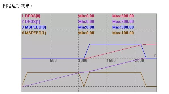
TRIGGER 'Automatic trigger oscilloscope
MOVE(100) AXIS(1) 'Axis 1 moves 100 and axis 0 does not move at this time
WAIT IDLE(1) 'The previous motion is not connected
CONNECT(0.5,1) AXIS(0) 'Axis 0 is connected to axis 1 with a ratio of 0.5
'CONNPATH(0.5,1) AXIS(0) 'Axis 0 is connected to axis 1 with a ratio of 0.5
MOVE(100) AXIS(1) 'Axis 1 movement 100
Axis 0 movement distance: 100*1000*0.5/100=500
5. Instructions and precautions
CONNECT synchronous motion and CONNPATH synchronous motion 2 are both electronic gear connection commands, and their syntax rules are the same.
CONNECT is connected to the measurement length. The number of pulses sent by the spindle single axis * connection ratio = the number of pulses sent by the following axis, that is, when the connection ratio is the same, the number of pulses sent by the spindle single axis is equal to the number of pulses sent by the following axis.
CONNPATH connects the interpolation vector length. The number of pulses sent by the interpolation synthesis axis * connection ratio = the number of pulses sent by the following axis, that is, when the connection ratio is the same, the number of pulses sent by the interpolation motion synthesized by the main axis and other axes is the same as that sent by the following axis.
CONNPATH has the same effect of motion as CONNECT if it is connected to a single axis.
Part III Application Cases of electronic gears
1. Schematic diagram of controller
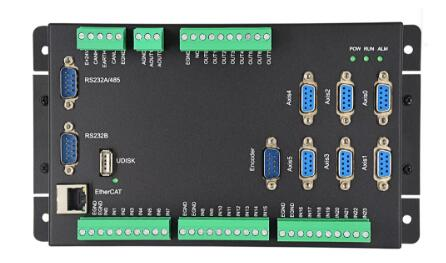
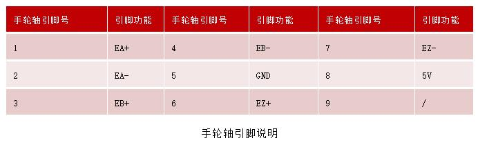
Schematic diagram of ZMC006CE handwheel interface (Encoder)
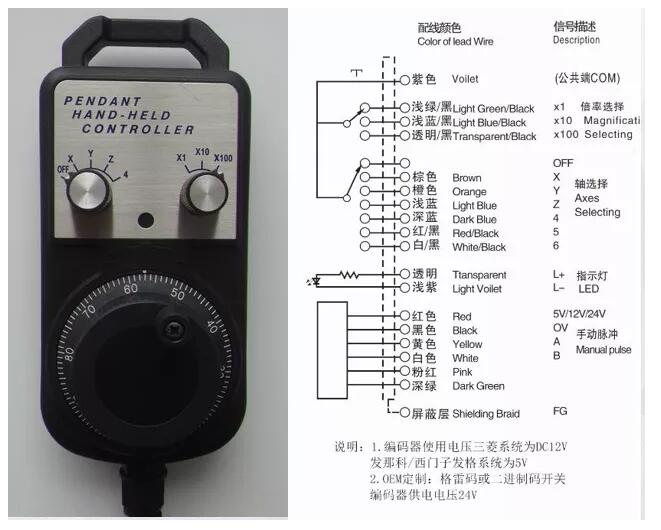
2. Schematic diagram of hand wheel
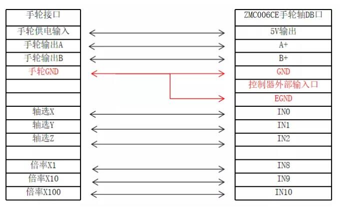
3. Wiring between handwheel and ZMC006CE handwheel shaft
4. Handwheel position compensation - ladder routine
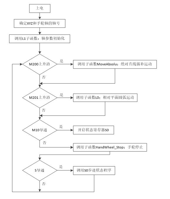
Ladder program structure: after power on, cycle scanning to judge the state of auxiliary relay M, so as to call different subroutines for execution. The status of auxiliary relay M is controlled by HMI interface.
Handwheel application ladder program:
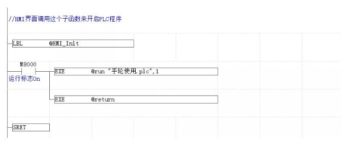
The following sub function has nothing to do with the main program. It is used to start the PLC file task in the HMI initialization function. The upper PLC file is opened by the automatic operation task number. If the automatic operation of PLC file is not set, the lower program can be called.
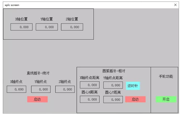
Hand wheel application case interface effect
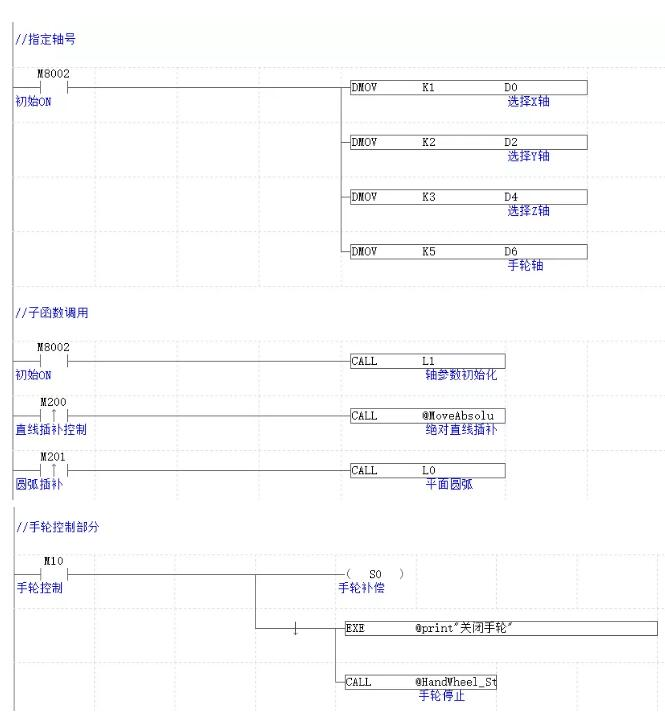
//Specify shaft number
ld m8002
DMOV K1 D0
DMOV K2 D2
DMOV K3 D4
DMOV K5 D6
//Sub function call
ld m8002
CALL L1
LDP M200
CALL @MoveAbsolu
LDP M201
CALL L0
//Handwheel control part
LD M10
out s0
ed
exe @print"Close the handwheel"
call @HandWheel_Stop
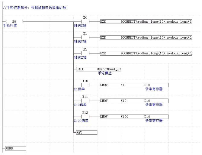
//Handwheel control part: select the drive shaft and connection ratio according to the knob
STL S0
MPS
AND X0
EXE @CONNECT(modbus_long(10),modbus_long(6)) AXIS(modbus_long(0))
MRD
AND X1
EXE @CONNECT(modbus_long(10),modbus_long(6)) AXIS(modbus_long(2))
MRD
AND X2
EXE @CONNECT(modbus_long(10),modbus_long(6)) AXIS(modbus_long(4))
MRD
call @HandWheel_Stop
AND X10
DMOV K1 D10
MRD
AND X11
DMOV K10 D10
MPP
AND X12
DMOV K100 D10
RET
fend
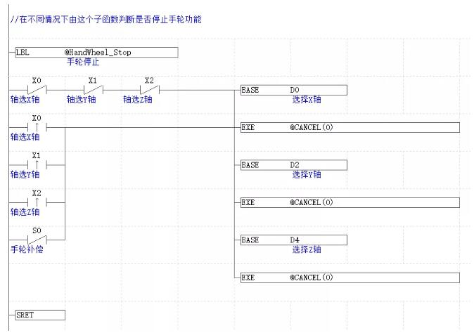
//In different cases, this sub function determines whether to stop the handwheel function
lbl @HandWheel_Stop
ldi x0
ANI X1
ANI X2
ORP X0
ORP X1
ORP X2
ORI S0
Base d0
exe @CANCEL(0)
Base d2
exe @CANCEL(0)
base d4
exe @CANCEL(0)
sret
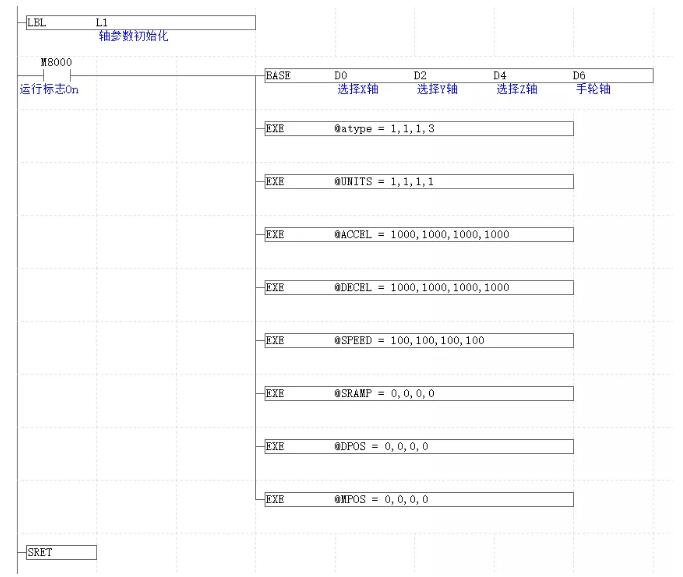
//Initialize selection axis
lbl l1
ld m8000
BASE D0 D2 D4 D6
EXE @atype = 1,1,1,3
EXE @UNITS = 1,1,1,1
EXE @ACCEL = 1000,1000,1000,1000
EXE @DECEL = 1000,1000,1000,1000
EXE @SPEED = 100,100,100,100
EXE @SRAMP = 0,0,0,0
EXE @DPOS = 0,0,0,0
EXE @MPOS = 0,0,0,0
sret
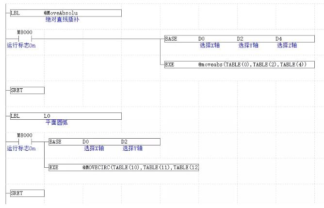
LBL @MoveAbsolu
ld m8000
base d0 d2 d4
exe @moveabs(TABLE(0),TABLE(2),TABLE(4))
sret
LBL l0
ld m8000
base d0 d2
exe @MOVECIRC(TABLE(10),TABLE(11),TABLE(12),TABLE(13),MODBUS_BIT(100))
sret
This time, the PLC programming of EtherCAT motion controller (III) - electronic gear is shared here.
For more interesting content, please pay attention to the "public assistant" official account, and you need the relevant development environment and routine code. Please consult the sales engineer of the sports technology.
This article is original by positive motion technology. You are welcome to reprint it and learn together to improve China's intelligent manufacturing level. The copyright of this article belongs to rightmovement technology. If you reprint it, please indicate the source of the article.