1. Project introduction
This is a small project of pointer electronic clock + perpetual calendar designed based on STM32. It uses a 3.5-inch LCD screen to display the clock, calendar, temperature and weather. It supports the touch screen to adjust the setting time, set the alarm clock, view the calendar, etc. The main technical point of the overall project is the graphic drawing of LCD screen. For example: clock drawing, minute hand, second hand, dial, calendar drawing, etc.
The time of the clock directly adopts the RTC clock of STM32 itself, and the indoor room temperature data is obtained by DS18B20 temperature sensor. The specific model of STM32 chip is STM32F103ZET6. As long as it is the development board of STM32F1 series, the code can be universal.
The LCD display adopts the 3.5-inch TFT display of punctual atom, supports 8080 timing, and has its own touch screen function. The touch screen is a resistance screen, the driver chip is XPT2046, SPI interface, and communication is very convenient.
STM32F103ZET6 has FSMC function and can output 8080 timing. In this project, FSMC control is used to drive LCD screen, with high efficiency.
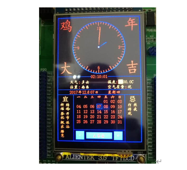
The main interface is as follows:
Project source code download address: https://download.csdn.net/download/xiaolong1126626497/63897554
Project video presentation address:
Pointer electronic clock and calendar based on STM32
2. Project function introduction
Each sub function page is explained in detail below.
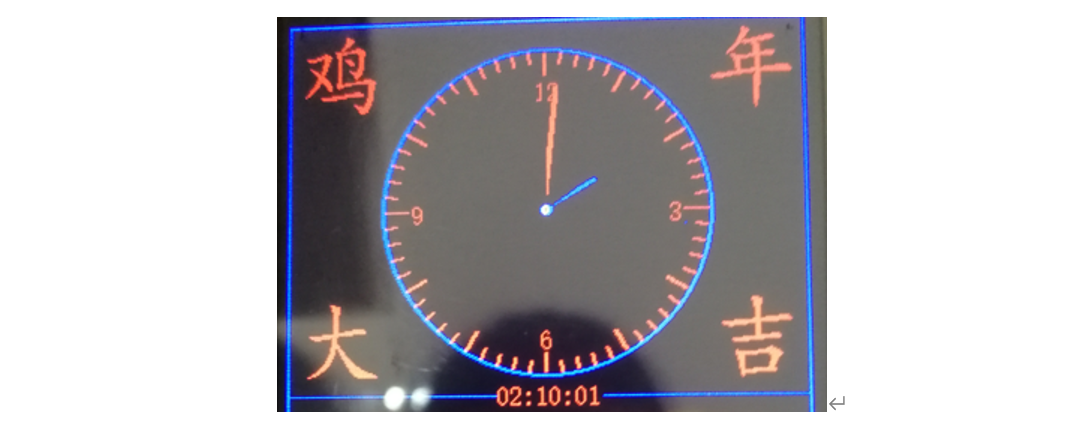
2.1 real time clock page
Display the dial, minute hand, hour hand, second hand, scale and change the clock time box above the LCD screen, realize the movement of minute hand, hour hand and second hand, and synchronously display the digital clock below the real-time clock.
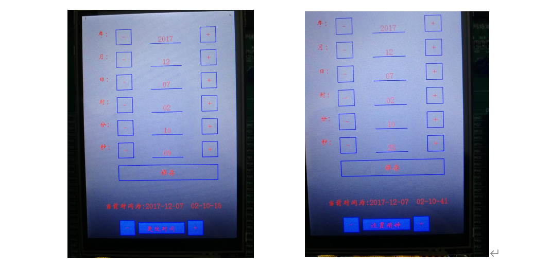
Use the touch screen function to realize the clock setting function, click "+" "-" to the clock setting box, and the clock setting interface will pop up to start setting the clock and date; Click "+" "-" to set the alarm clock box, and the alarm clock setting interface will pop up to start setting the alarm clock.
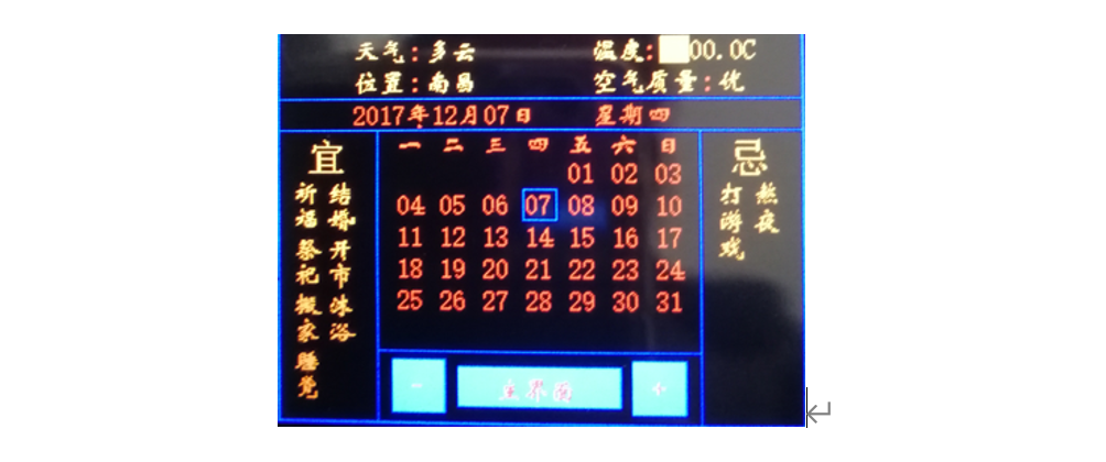
2.2 calendar page
The date, week, weather and real-time temperature are displayed in the middle of the LCD screen, the calendar is displayed below the LCD screen, the Yellow calendar is displayed on the left and right sides, and today's date is highlighted on the calendar.
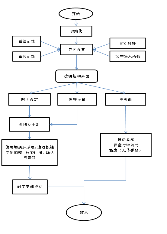
3. Explanation of main procedures for project realization
3.1 flow chart
3.2 ds18b2.c code
The main codes of DS18B20 temperature sensor are listed below
#include "ds18b20.h"
#include "delay.h"
//Reset DS18B20
void DS18B20_Rst(void)
{
DS18B20_IO_OUT(); //SET PG11 OUTPUT
DS18B20_DQ_OUT=0; //Pull down DQ
DelayUs(750); //Pull down 750us
DS18B20_DQ_OUT=1; //DQ=1
DelayUs(15); //15US
}
//Waiting for a response from DS18B20
//Return 1: the existence of DS18B20 is not detected
//Return 0: exists
u8 DS18B20_Check(void)
{
u8 retry=0;
DS18B20_IO_IN(); //SET PG11 INPUT
while (DS18B20_DQ_IN&&retry<200)
{
retry++;
DelayUs(1);
};
if(retry>=200)return 1;
else retry=0;
while (!DS18B20_DQ_IN&&retry<240)
{
retry++;
DelayUs(1);
};
if(retry>=240)return 1;
return 0;
}
//Read a bit from DS18B20
//Return value: 1 / 0
u8 DS18B20_Read_Bit(void)
{
u8 data;
DS18B20_IO_OUT(); //SET PG11 OUTPUT
DS18B20_DQ_OUT=0;
DelayUs(2);
DS18B20_DQ_OUT=1;
DS18B20_IO_IN(); //SET PG11 INPUT
DelayUs(12);
if(DS18B20_DQ_IN)data=1;
else data=0;
DelayUs(50);
return data;
}
//Read a byte from DS18B20
//Return value: read data
u8 DS18B20_Read_Byte(void)
{
u8 i,j,dat;
dat=0;
for (i=1;i<=8;i++)
{
j=DS18B20_Read_Bit();
dat=(j<<7)|(dat>>1);
}
return dat;
}
//Write a byte to DS18B20
//dat: bytes to write
void DS18B20_Write_Byte(u8 dat)
{
u8 j;
u8 testb;
DS18B20_IO_OUT(); //SET PG11 OUTPUT;
for (j=1;j<=8;j++)
{
testb=dat&0x01;
dat=dat>>1;
if (testb)
{
DS18B20_DQ_OUT=0; // Write 1
DelayUs(2);
DS18B20_DQ_OUT=1;
DelayUs(60);
}
else
{
DS18B20_DQ_OUT=0; // Write 0
DelayUs(60);
DS18B20_DQ_OUT=1;
DelayUs(2);
}
}
}
//Start temperature conversion
void DS18B20_Start(void)
{
DS18B20_Rst();
DS18B20_Check();
DS18B20_Write_Byte(0xcc); // skip rom
DS18B20_Write_Byte(0x44); // convert
}
//Initialize the IO port DQ of DS18B20 and detect the existence of DS at the same time
//Return 1: does not exist
//Return 0: exists
u8 DS18B20_Init(void)
{
RCC->APB2ENR|=1<<8; //Enable PORTG port clock
GPIOG->CRH&=0XFFFF0FFF; //PORTG.11 push pull output
GPIOG->CRH|=0X00003000;
GPIOG->ODR|=1<<11; //Output 1
DS18B20_Rst();
return DS18B20_Check();
}
//Get the temperature value from ds18b20
//Accuracy: 0.1C
//Return value: temperature value (- 550 ~ 1250)
short DS18B20_Get_Temp(void)
{
u8 temp;
u8 TL,TH;
short tem;
DS18B20_Start (); // ds1820 start convert
DS18B20_Rst();
DS18B20_Check();
DS18B20_Write_Byte(0xcc); // skip rom
DS18B20_Write_Byte(0xbe); // convert
TL=DS18B20_Read_Byte(); // LSB
TH=DS18B20_Read_Byte(); // MSB
if(TH>7)
{
TH=~TH;
TL=~TL;
temp=0; //The temperature is negative
}else temp=1; //The temperature is positive
tem=TH; //Get the top eight
tem<<=8;
tem+=TL; //Get the bottom eight
tem=(float)tem*0.625; //transformation
if(temp)return tem; //Return temperature value
else return -tem;
}
3.3 lcd Screen graphics rendering core algorithm
The functions of the whole project are LCD On the display screen, you need to draw line segments, circles, rectangles, angle line segments, Chinese, numbers, etc. the core codes of this part are listed below.
/*
Function function: draw horizontal line
Function parameters: x,y: coordinates
length:length
*/
void LcdDrawThwartLine(u16 x,u16 y,u16 length,u16 color)
{
u16 i;
for(i=0;i<length;i++)
{
LcdDrawPoint(x+i,y,color);
}
}
/*
Function: draw a vertical line
Function parameters: x,y: coordinates
length:length
*/
void LcdDrawVerticalLine(u16 x,u16 y,u16 length,u16 color)
{
u16 i;
for(i=0;i<length;i++)
{
LcdDrawPoint3(x,y+i,color);
}
}
/*
Function function: draw rectangle
Function parameters: x,y: coordinates
length:long
width:wide
*/
void LcdDrawRectangle(u16 x,u16 y,u16 length,u16 width,u16 color)
{
LcdDrawThwartLine(x,y,length,color);
LcdDrawVerticalLine(x,y,width,color);
LcdDrawThwartLine(x,y+width,length,color);
LcdDrawVerticalLine(x+length,y,width,color);
}
//Draw a line at two points
//x1,y1: starting point coordinates
//x2,y2: end coordinates
void LcdDrawLine(u16 x1, u16 y1, u16 x2, u16 y2,u16 color)
{
u16 t;
int xerr=0,yerr=0,delta_x,delta_y,distance;
int incx,incy,uRow,uCol;
delta_x=x2-x1; //Calculate coordinate increment
delta_y=y2-y1;
uRow=x1;
uCol=y1;
if(delta_x>0)incx=1; //Set single step direction
else if(delta_x==0)incx=0;//Vertical line
else {incx=-1;delta_x=-delta_x;}
if(delta_y>0)incy=1;
else if(delta_y==0)incy=0;//level
else{incy=-1;delta_y=-delta_y;}
if( delta_x>delta_y)distance=delta_x; //Select basic incremental axis
else distance=delta_y;
for(t=0;t<=distance+1;t++ )//Draw line output
{
LcdDrawPoint(uRow,uCol,color);//Draw point
xerr+=delta_x ;
yerr+=delta_y ;
if(xerr>distance)
{
xerr-=distance;
uRow+=incx;
}
if(yerr>distance)
{
yerr-=distance;
uCol+=incy;
}
}
}
//Draw a circle of the specified size at the specified position
//(x,y): center point
//r: radius
void LcdDraw_Circle(u16 x0,u16 y0,u8 r,u16 color)
{
int a,b;
int di;
a=0;b=r;
di=3-(r<<1); //Mark for judging the position of the next point
while(a<=b)
{
LcdDrawPoint(x0+a,y0-b,color); //5
LcdDrawPoint(x0+b,y0-a,color); //0
LcdDrawPoint(x0+b,y0+a,color); //4
LcdDrawPoint(x0+a,y0+b,color); //6
LcdDrawPoint(x0-a,y0+b,color); //1
LcdDrawPoint(x0-b,y0+a,color);
LcdDrawPoint(x0-a,y0-b,color); //2
LcdDrawPoint(x0-b,y0-a,color); //7
a++;
//Draw a circle using Bresenham algorithm
if(di<0)di +=4*a+6;
else
{
di+=10+4*(a-b);
b--;
}
}
}
/*
Function: draw a straight line from any angle
Parameters:
w : Start with the center of the circle and don't draw the length
len:radius
c :colour
x,y:coordinate
Actual length = len-w
*/
void LcdDrawAngleLine(u32 x,u32 y,float du,u32 len,u32 w,u16 c)
{
int i;
int x0,y0;
float k=du*(3.1415926535/180);
for(i=len-w;i<len;i++)
{
x0=cos(k)*i;
y0=sin(k)*i;
LcdDrawPoint(x+x0,y+y0,c);
}
}
/*
Function function: rectangle color filling
Parameters: (sx,sy),(ex,ey): rectangular diagonal coordinates
color:Color to fill
*/
void LcdFill(u16 sx,u16 sy,u16 ex,u16 ey,u16 color)
{
u16 i,j;
u16 xlen=0;
xlen=ex-sx+1;
for(i=sy;i<=ey;i++)
{
LcdSetCursor(sx,i); //Set cursor position
LcdWriteReg(0X2C); //Start writing GRAM
for(j=0;j<xlen;j++)LcdWriteData(color);
}
}
/*
Function: draw lines at any angle
x0,y0:Starting point coordinates
a: angle
c: colour
n: length
*/
void LcdDrawAngleLine2(u32 x0,u32 y0,double a,u16 n,u16 c,u16 mode)
{
u32 x,y;
u32 i;
double p=a*3.1415926535/180;
for(i=0;i<=n;i++) //n is the length
{
x=i*cos(p)+x0;
y=i*sin(p)+y0;
if(mode==1)LcdDrawPoint(x,y,c); //Draw point
else if(mode==2) LcdDrawPoint2(x,y,c); //Draw point
else LcdDrawPoint3(x,y,c); //Draw point
}
}
/*
Function function: draw points (BOLD)
Function parameters: x,y: coordinates
*/
void LcdDrawPoint2(u16 x,u16 y,u16 color)
{
LcdSetCursor(x,y); //Set cursor position
LcdWriteReg(0X2C); //Start writing GRAM
LcdWriteData(color); //Write data
LcdWriteData(color); //Write data
LcdWriteData(color); //Write data
// LcdWriteData(color); // Write data
// LcdWriteData(color); // Write data
// LcdWriteData(color); // Write data
// LcdWriteData(color); // Write data
}
/*
Function function: draw points (thinning)
Function parameters: x,y: coordinates
*/
void LcdDrawPoint3(u16 x,u16 y,u16 color)
{
LcdSetCursor(x,y); //Set cursor position
LcdWriteReg(0X2C); //Start writing GRAM
LcdWriteData(color); //Write data
// LcdWriteData(color); // Write data
// LcdWriteData(color); // Write data
// LcdWriteData(color); // Write data
// LcdWriteData(color); // Write data
// LcdWriteData(color); // Write data
// LcdWriteData(color); // Write data
}
/*
Function function: draw lines from any angle, standard bold
void LcdDrawAngleLine2(u32 x0,u32 y0,double a,u32 n,u32 c,u32 mode)
*/
void Lcdline_add(u32 x,u32 y,double a,u16 n,u16 c, u8 add )
{
u8 i;
for(i=1;i<add;i++)
{
x-=i;
y-=i;
LcdDrawAngleLine2(x,y,a,n,c,1);
}
for(i=1;i<add;i++)
{
x+=i;
y+=i;
LcdDrawAngleLine2(x,y,a,n,c,1);
}
}