24.1 about DMA
DMA(Direct Memory Access) direct memory access can greatly reduce the workload of CPU. The CPU executes instructions according to the content of the code. Some of these instructions are used for calculation, some for control programs, and some for transferring data. Among them, the instructions to transfer data, especially a large amount of data, will occupy a large amount of CPU. If the data of peripheral A is transmitted to peripheral B, the CPU does not need to be involved all the time. Just create a channel between a and B and let them transmit themselves. This is the purpose of DMA design to reduce the CPU consumption of a large number of data transfer instructions. DMA focuses on data transfer and CPU focuses on calculation and control.
DMA is mainly used to directly transport the data from A to B. here, A and B can be memory (internal / external SRAM, etc.) or peripherals (UART, I2C, SPI, ADC, etc.). Therefore, all scenarios are as follows:
- Memory to peripherals
- Peripheral to memory
- Memory to memory
Regardless of the above methods, set the data source address, data destination address and data length of DMA first. After setting, start DMA to automatically transfer the data from the source address to the target address.
24.1.2 DMA structure
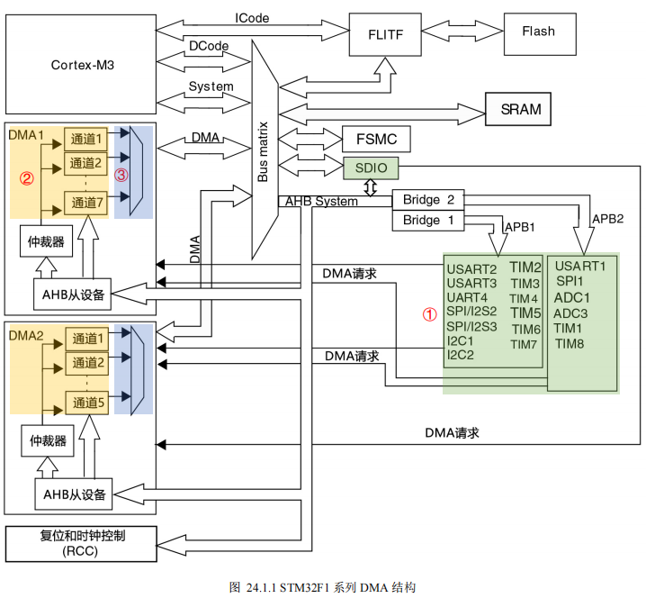
STM32F1 series has two DMA controllers, among which DMA2 only exists in high-capacity products. DMA1 has 7 channels and DMA2 has 5 channels, a total of 12 channels. As shown in figure 24.1.1, STM32F1 series DMA structure can be divided into three parts.
① DMA request: if the peripheral wants to transmit data through DMA, it needs to send a request to the DMA controller first. After the peripheral sends a request to the DMA controller, the DMA controller processes the request in turn according to the channel priority. When it is the peripheral's turn, it returns a response signal to the peripheral. The peripheral receives the response signal, releases the request and carries out DMA data transmission until the DMA transmission ends;
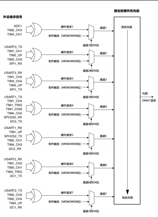
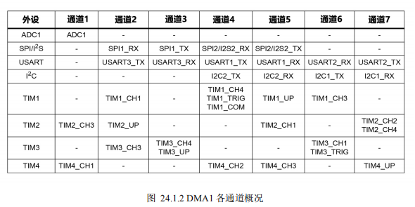
② DMA channel: different peripherals send requests to different channels of different DMA, as shown in figure 24.1.2 and figure 24.1.3. For example, if ADC1 wants to use DMA, it should send a request to channel 1 of DMA1. Channel 1 of DMA1 can receive requests from multiple peripherals (ADC1, TIM2_CH3, TIM4_CH1), but only one can be received at the same time;
③ DMA priority: when multiple DMA channels send requests at the same time, obtain the software configuration DMA_ The priority set by ccrx register responds in turn. When the software configuration priority is the same, the one with high hardware priority (small channel number) will give priority to response. Among products with DMA2, DMA1 has higher priority than DMA1.

DMA can transmit up to 65536 data at a time. DMA will generate three transmission flags during transmission: Half Transfer (HT), Transfer Complete (TC) and Transfer Error (TE). Each flag will generate a corresponding interrupt signal, and developers can process the corresponding program through these three flags.
If there are N data to be transferred by DMA, after setting to the original address and destination address, when receiving a transfer request, DMA will take out a data from the original address and transfer it to the destination address. If the address is a peripheral, the address remains unchanged. If the address is memory, the address will increase by one data unit after transmitting a data. In the process of transmission, if an unexpected error occurs, an error interrupt signal will be generated. When the transmission is half completed, a half transmission completion interrupt will be generated. When all data transmission is completed, a transmission completion interrupt will be generated.
24.2 hardware design
The MCU is designed for internal use, but not for external use.
24.3 software design
24.3.1 software design idea
Objective: this experiment uses DMA to realize the data transfer from memory to memory in internal RAM, so that readers can experience the basic usage of DMA.
- Initialize DMA: select DMA channel, DMA transmission direction, transmission data size, etc;
- Start DMA transfer and register the transfer completion callback function;
- Compare the data before and after transmission to check whether the transmission is successful;
The supporting code of this experiment is located in "5 program source code \ 16 Porter DMA \".
24.3.2 software design explanation
- DMA initialization
DMA memory to memory initialization is relatively simple, as shown in code segment 24.3.1.
Code snippet 24.3.1 DMA initialization (driver_dma.c)
/*
* Function name: void DMA_M2M_Init(void)
* Input parameters: None
* Output parameters: None
* Return value: None
* The DMA initialization function initializes DMA_Channel1, configured as memory memory mode, moves one word at a time, i.e. 4bytes
*/
void DMA_M2M_Init(void) {
__HAL_RCC_DMA1_CLK_ENABLE(); // Enable DMA1 clock
hdma.Init.Direction = DMA_MEMORY_TO_MEMORY; // Memory - > memory mode
hdma.Init.PeriphInc = DMA_PINC_ENABLE; // Peripheral address increment
hdma.Init.MemInc = DMA_MINC_ENABLE; // Memory address increment
hdma.Init.PeriphDataAlignment = DMA_PDATAALIGN_WORD; // Align peripheral data with words
hdma.Init.MemDataAlignment = DMA_MDATAALIGN_WORD; // Memory data aligned with words
hdma.Init.Mode = DMA_NORMAL; // DMA normal transmission mode
hdma.Init.Priority = DMA_PRIORITY_VERY_HIGH; // Set very high priority in DMA transmission
hdma.Instance = DMA1_Channel1; // Select DMA channel 1
// Initialize DMA configuration using library functions
if(HAL_DMA_Init(&hdma) != HAL_OK)
{
Error_Handler(); }
// Register transfer completion and transfer error callback functions
HAL_DMA_RegisterCallback(&hdma, HAL_DMA_XFER_CPLT_CB_ID, TransferComplete);
HAL_DMA_RegisterCallback(&hdma, HAL_DMA_XFER_ERROR_CB_ID, TransferError);
// Configure DMA interrupt priority and enable
HAL_NVIC_SetPriority(DMA1_Channel1_IRQn, 0, 0);
HAL_NVIC_EnableIRQ(DMA1_Channel1_IRQn); }
- Line 10: enable DMA1 clock;
- Line 12: set the transmission direction of DMA, here is memory to memory;
- Line 13: set the peripheral address increment, which does not involve peripherals and can be set arbitrarily;
- Line 14: set the memory address increment, that is, each time DMA transmits a data, the address will automatically increment, and the next address data will be transmitted next time;
- Line 15: set the data width of peripheral equipment. It does not involve peripheral equipment and can be set arbitrarily;
- Line 16: set the width of memory data. Here, set the width bit to transmit by word (16 bits);
- Line 17: set the DMA working mode to support cyclic transmission, which is set as the default single transmission here;
- Line 18: set DMA priority to very high;
- Line 19: select DMA1 channel 1; lines 21 ~ 25: DMA initialization;
- Lines 27 ~ 29: register the callback function of transmission completion and transmission error;
- Line 32: configure the interrupt priority of DMA1 channel 1;
- Line 33: enable the interruption of DMA1 channel 1;
- Start DMA transfer
After initialization, you can use "HAL_DMA_Start()" or "HAL_DMA_Start_IT()" provided by the HAL library to start the transmission. Interrupt is used in this example, so the latter is used, as shown in code segment 24.3.2.
Code snippet 24.3.2 start DMA transfer (driver_dma.c)
/*
* Function name: void DMA_M2M_Start(uint32_t *srcAddr, uint32_t *dstAddr, uint16_t bufsz
* Input parameter: srcAddr - original address of data
* dstAddr-DMA Destination address of the move
* bufsz-DMA The size and unit of the moved data are selected during initialization: byte, half word, word
* Output parameters: None
* Return value: None
* The DMA initialization function initializes DMA_Channel1, configured as memory memory mode, moves one word at a time, i.e. 4bytes
*/
void DMA_M2M_Start(uint32_t *srcAddr, uint32_t *dstAddr, uint16_t bufsz)
{
if (HAL_DMA_Start_IT(&hdma, (uint32_t)srcAddr, (uint32_t)dstAddr, bufsz) != HAL_OK)
{
Error_Handler(); } }
Data transmission has three elements: source address, destination address and transmission length. "HAL_DMA_Start_IT()" also follows this principle, see
The numbers are:
- hdma: pointing to DMA_ A pointer to the handletypedef structure, which contains the configuration information of the specified DMA channel;
- SrcAddress: the source address of the data to be transmitted;
- DstAddress: the destination address for data transmission;
- DataLength: length of transmitted data;
- Implement callback function
When DMA transmission is completed or an error occurs during transmission, the previously registered callback function will be called back. The processing content of the callback function is realized here, as shown in code segment 24.3.3.
Code segment 24.3.3 implementation of DMA callback function (driver_dma.c)
*
* Function name: void TransferComplete(DMA_HandleTypeDef *DmaHandle)
* Input parameters: DmaHandle-DMA handle
* Output parameters: None
* Return value: None
* Function function: if DMA If the transmission is completed and no error occurs, set the transmission completion flag to one in this function
*/
static void TransferComplete(DMA_HandleTypeDef *DmaHandle)
{
transferCompleteDetected = 1; }
/*
* Function name: void TransferError(DMA_HandleTypeDef *DmaHandle)
* Input parameter: dmahandle DMA handle
* Output parameters: None
* Return value: None
* Function function: if an error occurs during DMA transmission, set the transmission error flag to one in this function
*/
static void TransferError(DMA_HandleTypeDef *DmaHandle)
{
transferErrorDetected = 1; }
//DMA1 channel 11 interrupt entry
void DMA1_Channel1_IRQHandler(void)
{
HAL_DMA_IRQHandler(&hdma); }
- Lines 8 ~ 11: if the DMA transfer is completed and no error occurs, set the transfer completion flag "transfercompleteddetected" to 1 in this function;
- Lines 20 ~ 23: if an error occurs during DMA transmission, set the transmission error flag "transferErrorDetected" to 1 in this function;
- Lines 26 ~ 29: DMA1 channel 11 interrupt entry;
- Main function control logic
In the main function, first prepare the data to be sent, and then use DMA to send the prepared data to the target location. After the transmission is completed, compare whether the source data and target data are consistent to judge whether the transmission is successful, as shown in code segment 24.3.4.
Code snippet 24.3.4 main function control logic (main.c)
// Initialize DMA
DMA_M2M_Init();
// Initialize USART1 and set the baud rate to 115200
UsartInit(115200);
// Initialization key
KeyInit();
printf("**********************************************\n\r");
printf("-->Baiwen Technology: www.100ask.net\n\r");
printf("-->DMA-DMA experiment\n\r");
printf("**********************************************\n\r");
while(1) {
if(step==0x00) // Press the key
{
step = 0xFF;
transferCompleteDetected = 0;
transferErrorDetected = 0;
DMA_M2M_Start(srcBuffer, dstBuffer, 20); // DMA start transfer
}
if(transferCompleteDetected==1) // Transfer complete detected
{
transferCompleteDetected = 0;
for(i=0;i<20;i++) // Compare whether the target data and source data are consistent one by one to judge whether there is a transmission error
{
if(dstBuffer[i] != srcBuffer[i])
{
printf("DMA Data transfer error occurred during data transmission\n\r"); }
else
{
printf("WriteBuffer: 0x%x \t ReadBuffer: 0x%x OK!\n\r", srcBuffer[i], dstBuffer[i]); } }
run_cnt++;
memset((uint32_t*)dstBuffer, 0, sizeof(uint32_t)*20); }
else if(transferErrorDetected==1) // Transmission error detected
{
transferErrorDetected = 0;
printf("DMA A transmission error occurred during data transmission\n\r"); } }
- Line 2: initialize DMA;
- Line 5: initialize the debugging serial port;
- Line 7: initialization key;
- Lines 16 ~ 22: when the key is pressed, clear all flag bits, start DMA transmission, and transmit 20 data each time;
- Lines 24 ~ 40: if the transmission completion flag is detected, compare the source data and target data one by one, and print the results;
- Lines 41 ~ 44: the transmission error flag is detected and the error result is printed;
24.4 experimental effect
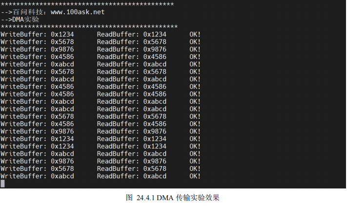
This experiment corresponds to "5 program source code \ 16 Porter DMA \" in the supporting materials. After opening the project, compile and download, press key 1 (KEY_U) to carry out a memory to memory DMA transmission, and print the transmission result on the serial port, as shown in figure 24.4.1.
Baiwen Technology Forum:
http://bbs.100ask.net/
Baiwen embedded video official website:
https://www.100ask.net/index
Baiwen development board:
TaoBao: https://100ask.taobao.com/
Tmall: https://weidongshan.tmall.com/
Technical exchange group 2 (Hongmeng development / Linux / embedded / driver / data download)
QQ group: 752871361
MCU embedded Linux communication group:
QQ group: 536785813
Weidongshan embedded training course exchange group ③
QQ group: 717041375