04 C language and screen display practice
In the original text, the author has made great efforts to explain the knowledge of C language, which will not be covered here..
1. Display mode and memory
The content author of the previous day set the display of our operating system to VGA 320*200 8-bit palette mode, 8-bit means that we can use 256 colors, but in essence, VGA is RGB color mode, which requires 3 bytes to represent a complete color. We can only set the color number, which is a mapping of 8-bit to 24-bit color. The setting method will be introduced later.
And set the display resolution to 320 * 200, each pixel needs a byte (8 bits) to represent the color
In this mode, the address range of the video memory is 0xa0000 -0xaffff, but only 320 * 200 bytes are needed for a pixel to store a byte, but the video memory range is 64K larger than that of the stored pixel, and I don't know why..
2. Assembly for memory writing
_write_mem8: ; void write_mem8(int addr, int data);
    MOV ECX,[ESP+4] ; [ESP + 4]The address stored in is read in ECX
    MOV AL,[ESP+8] ; [ESP + 8]Data stored in, read it in AL
    MOV [ECX],AL
RET
Here is the 32-bit mode, so the registers we use are expansion registers. Here, the function parameters of C compiler are pushed from right to left, so we simply write a 32-bit data to the memory of the specified 32-bit address
3. Color number setting
As mentioned earlier, our display mode is VGA 8-bit palette mode, which requires you to specify different colors for different 256 color numbers. The author uses 16 colors to draw his operating system, as follows:
static unsigned char table_rgb[16 * 3] = {
	0x00, 0x00, 0x00,	/*  0:black */
	0xff, 0x00, 0x00,	/*  1:Liang Hong */
	0x00, 0xff, 0x00,	/*  2:Bright green */
	0xff, 0xff, 0x00,	/*  3:Bright yellow */
	0x00, 0x00, 0xff,	/*  4:Brilliant blue */
	0xff, 0x00, 0xff,	/*  5:Bright violet */
	0x00, 0xff, 0xff,	/*  6:Light brilliant blue */
	0xff, 0xff, 0xff,	/*  7:white */
	0xc6, 0xc6, 0xc6,	/*  8:Bright grey */
	0x84, 0x00, 0x00,	/*  9:Dull red */
	0x00, 0x84, 0x00,	/* 10:Dark green */
	0x84, 0x84, 0x00,	/* 11:Dark yellow */
	0x00, 0x00, 0x84,	/* 12:Dark blue */
	0x84, 0x00, 0x84,	/* 13:Dark purple */
	0x00, 0x84, 0x84,	/* 14:Light dark blue */
	0x84, 0x84, 0x84	/* 15:Dark grey */
};
At the same time, the author provides many functions to help write such as port:
void io_hlt(void); // Hover CPU before
void io_cli(void); // Interrupt identification bit reset
void io_out8(int port, int data);	// Output 8-bit data
int io_load_eflags(void);	// Returns the value of the representation register
void io_store_eflags(int eflags); // Using eflags overload to represent register
The assembly is realized as follows:
; naskfunc
; TAB=4

[FORMAT "WCOFF"]				; Mode of making target file
[INSTRSET "i486p"]				; Use instructions up to 486
[BITS 32]						; 3 Machine language for making 32-bit mode
[FILE "naskfunc.nas"]			; file name

		GLOBAL	_io_hlt, _io_cli, _io_sti, _io_stihlt
		GLOBAL	_io_in8,  _io_in16,  _io_in32
		GLOBAL	_io_out8, _io_out16, _io_out32
		GLOBAL	_io_load_eflags, _io_store_eflags

[SECTION .text]

_io_hlt:	; void io_hlt(void);
		HLT
		RET

_io_cli:	; void io_cli(void);
		CLI
		RET

_io_sti:	; void io_sti(void);
		STI
		RET

_io_stihlt:	; void io_stihlt(void);
		STI
		HLT
		RET

_io_in8:	; int io_in8(int port);
		MOV		EDX,[ESP+4]		; port
		MOV		EAX,0
		IN		AL,DX
		RET

_io_in16:	; int io_in16(int port);
		MOV		EDX,[ESP+4]		; port
		MOV		EAX,0
		IN		AX,DX
		RET

_io_in32:	; int io_in32(int port);
		MOV		EDX,[ESP+4]		; port
		IN		EAX,DX
		RET

_io_out8:	; void io_out8(int port, int data);
		MOV		EDX,[ESP+4]		; port
		MOV		AL,[ESP+8]		; data
		OUT		DX,AL
		RET

_io_out16:	; void io_out16(int port, int data);
		MOV		EDX,[ESP+4]		; port
		MOV		EAX,[ESP+8]		; data
		OUT		DX,AX
		RET

_io_out32:	; void io_out32(int port, int data);
		MOV		EDX,[ESP+4]		; port
		MOV		EAX,[ESP+8]		; data
		OUT		DX,EAX
		RET

_io_load_eflags:	; int io_load_eflags(void);
		PUSHFD		; PUSH EFLAGS
		POP		EAX
		RET

_io_store_eflags:	; void io_store_eflags(int eflags);
		MOV		EAX,[ESP+4]
		PUSH	EAX
		POPFD		; POP EFLAGS
		RET
The right IN OUT instructions IN the code are necessary instructions for the interaction between CPU and other input and output devices. IN reads data from the specified port, and OUT writes data. Note that the return values of functions IN assembly (compiled IN C language) are all through EAX registers
Next, to really set the color number, the VGA palette mode setting process is as follows:
- First, mask interrupts (such as CLI) in a series of accesses.
- Write the palette number you want to set to 0x03c8, and then write it in the order of R, G, B
0x03c9. If you want to continue to set the next palette, omit the palette number, and then follow the RGB
Write 0x03c9 in sequence. - If you want to read the status of the palette, first you need to write the palette number to 0x03c7, and then from the
0x03c9 read 3 times. The order of reading is R, G, B. If you want to continue reading the next palette, the same as
The sample also omits the palette number setting and reads in RGB order. - If CLI is executed initially, STI is executed last
The corresponding C language code is as follows:
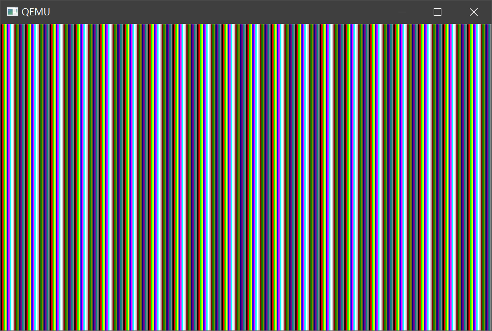
void io_hlt(void);
void io_cli(void);
void io_out8(int port, int data);
int io_load_eflags(void);
void io_store_eflags(int eflags);
/*Even if it is written in the same source file, if you want to use it before definition, you must declare it in advance. */
void init_palette(void);
void set_palette(int start, int end, unsigned char *rgb);
void HariMain(void)
{
	int i; /* Declare variables. Variable i is a 32-bit integer */
	char *p; /* Variable p is the address used by BYTE [...] */
	init_palette(); /* Set palette */
    p = (char *) 0xa0000; /* Designated address */
    for (i = 0; i <= 0xffff; i++) {
    	p[i] = i & 0x0f;
	}
    for (;;) {
		io_hlt();
	}
}

void init_palette(void)
{
    static unsigned char table_rgb[16 * 3] = {
        0x00, 0x00, 0x00, /* 0:black */
        0xff, 0x00, 0x00, /* 1:Bright red */
    	0x00, 0xff, 0x00, /* 2:Bright green */
        0xff, 0xff, 0x00, /* 3:Bright yellow */
        0x00, 0x00, 0xff, /* 4:Brilliant blue */
        0xff, 0x00, 0xff, /* 5:Bright violet */
        0x00, 0xff, 0xff, /* 6:Light brilliant blue */
        0xff, 0xff, 0xff, /* 7:white */
        0xc6, 0xc6, 0xc6, /* 8:Bright grey */
        0x84, 0x00, 0x00, /* 9:Dull red */
        0x00, 0x84, 0x00, /* 10:Dark green */
        0x84, 0x84, 0x00, /* 11:Dark yellow */
        0x00, 0x00, 0x84, /* 12:Dark blue */
        0x84, 0x00, 0x84, /* 13:Dark purple */
        0x00, 0x84, 0x84, /* 14:Light dark blue */
        0x84, 0x84, 0x84 /* 15:Dark grey */
	};
	set_palette(0, 15, table_rgb);
	return;
/* C The static char statement in the language can only be used for data, which is equivalent to the DB instruction in assembly */
}
void set_palette(int start, int end, unsigned char *rgb)
{
    int i, eflags;
    eflags = io_load_eflags(); /* Record the value of the interrupt permission flag*/
    io_cli(); /* Set interrupt permission flag to 0, disable interrupt */
    io_out8(0x03c8, start);
    for (i = start; i <= end; i++) {
    	io_out8(0x03c9, rgb[0] / 4);
    	io_out8(0x03c9, rgb[1] / 4);
    	io_out8(0x03c9, rgb[2] / 4);
		rgb += 3;
	}
    io_store_eflags(eflags); /* Restore interrupt permission flag */
	return;
}
The renderings are as follows:
3. Draw rectangle
The picture coordinate system is the top left coordinate system (the top left corner is the vertex), so for the coordinate (x,y), we only need to use 0xa0000 + x + y * 320 as the corresponding address of the coordinate, so it is much easier to draw the rectangle
Draw the rectangle code as follows:
/*
vram: Corresponding display address 0xa0000
xsize: Corresponding width
c: Color number
 Upper left lower right coordinate
*/
void boxfill8(unsigned char *vram, int xsize, unsigned char c, int x0, int y0, int x1, int y1)
{
	int x, y;
	for (y = y0; y <= y1; y++) {
		for (x = x0; x <= x1; x++)
			vram[y * xsize + x] = c;
	}
	return;
}
The renderings are as follows:
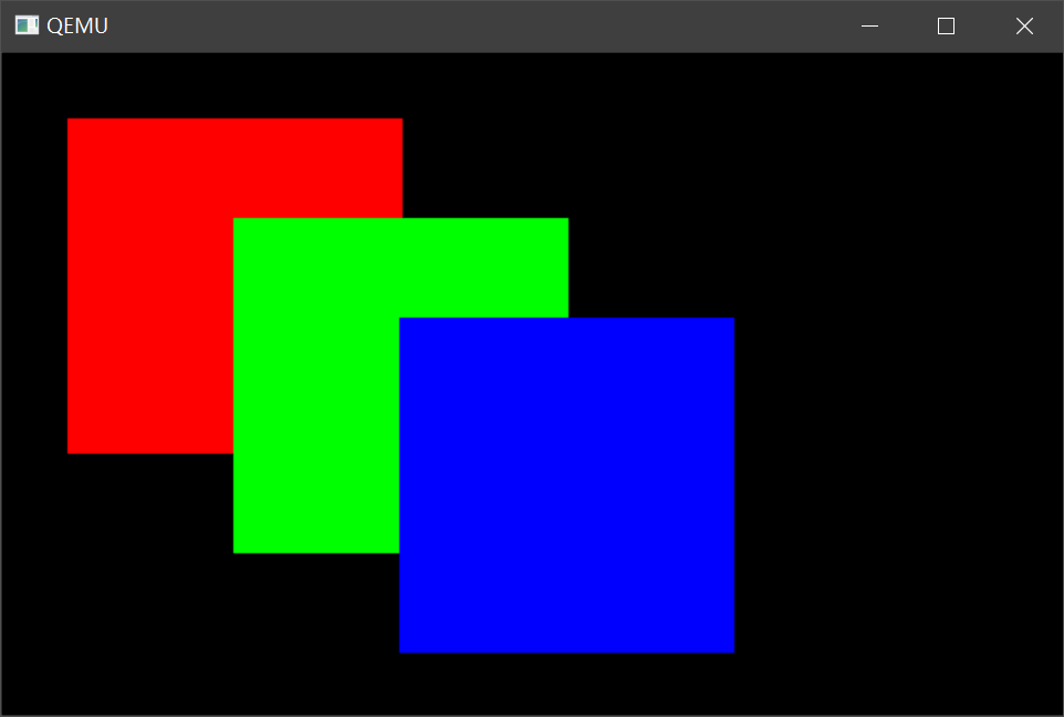
In the end, the author draws a simple interface, which is realized by drawing rectangles. That's not enough

