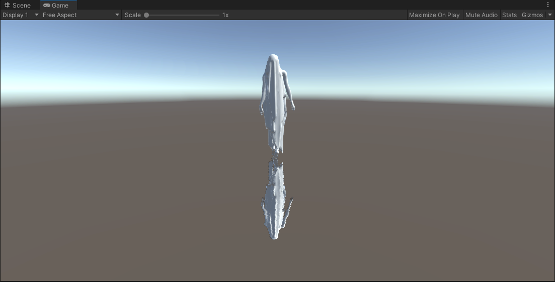
Overall thinking
This method does not rely on the shader, but uses the monobehavior script (mounted on the reflection plane or camera)
Core idea:
Simple and crude, use the script to create a new camera. The camera is consistent with the parameter position of the main camera. Just flip the image of the camera. The general steps are as follows:
- Create a camera
- Mirror rendered content
- Output RT
- Transfer to Shader for sampling processing
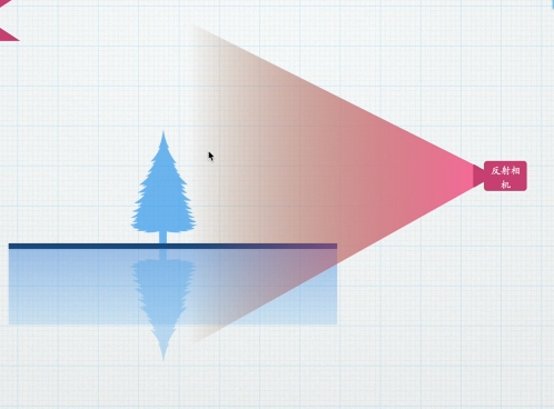
Create a reflection camera
Create a GameObject and set the name and type, then get the components of the main camera and copy the parameters
private Camera reflectionCam;

void Start()
{
   GameObject cam = new GameObject("ReflectionCamera", new System.Type[] { typeof(Camera) });
   reflectionCam = cam.GetComponent<Camera>();
   reflectionCam.CopyFrom(Camera.main);
}
Time to flip the image
To finally get the flipped image, you need to flip the image before the last step of rendering
Therefore, it is necessary to consider the timing of calculation in this step. Instead of Start or Update, use OnpreRender()
This method will be called before the camera is rendered, which is exactly what we need.
Use of OnBeginCameraRendering() method (URP)
(the BuildIn built-in pipeline uses void OnPreRender())
Need to declare unityengine Only the rendering class can be used
Input the complete method block with parameters, and flip before rendering will be carried out in this method
In the Start method, use renderpipelinemanager The begincamerarendering event calls up the method
using UnityEngine.Rendering;
void Start()
    {
        GameObject cam = new GameObject("ReflectionCamera", new System.Type[] { typeof(Camera) });
        reflectionCam = cam.GetComponent<Camera>();
        reflectionCam.CopyFrom(Camera.main);

        RenderPipelineManager.beginCameraRendering += OnBeginCameraRendering;

    }

    void OnBeginCameraRendering(ScriptableRenderContext context, Camera camera)
    {

    }
Reflection matrix transformation (simple version)
The process of vertex transformation from local space to clipping space is as follows

We choose to carry out reflection transformation in the process of world space camera space. The specific method is to multiply the two transformation matrices of reflection space and camera space. The result is consistent with multiplying one matrix first and then multiplying one matrix

Reflection matrix
If you only flip the image, just take Sy as a negative value (i.e. - 1)
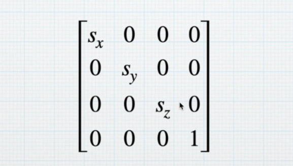
Preliminary code implementation
Method 1
Only the contents in the OnBeginCameraRendering method block are shown here
[3] To determine whether the camera is a reflection camera, we only flip the image of the reflection camera
[5] This flipping matrix will cause the culling to be flipped, so you need to flip the culling back here
[7] To create a 4x4 identity matrix, new is deliberately not used here to avoid redundancy caused by instances generated in each frame
[8] Set 1 row and 1 column (starting from 0), that is, the value of Sy is - 1
[9] We directly assign a value to the transformation matrix from world space to camera space, multiply the reflection matrix by the transformation matrix of the main camera, pay attention to the multiplication order here, and ensure that the last step of the vertex is to convert to camera space
  void OnBeginCameraRendering(ScriptableRenderContext context, Camera camera)
    {
        if (camera == reflectionCam)
        {
            GL.invertCulling = true;
            Method 1: directly change the second row and the second column in the matrix (starting from 0 here) Y Axis parameters
             Matrix4x4 reflectionM = Matrix4x4.identity;
             reflectionM.m11 = -1;
             camera.worldToCameraMatrix = reflectionM * Camera.main.worldToCameraMatrix;

        }
        else
        {
            GL.invertCulling = false;
        }

    }
Method 2
We use three three-dimensional vectors to expose the parameters directly
They are translation T, rotation R, and scaling S
Why three dimensions?
Coincidentally, Unity provides us with a way to set TRS (Matrix4x4.TRS()), and the transformation is only in these three dimensions
[12] R here needs to be converted into Euler angle to use
    public Vector3 T = Vector3.zero;
    public Vector3 R = Vector3.zero;
    public Vector3 S = Vector3.one;

void OnBeginCameraRendering(ScriptableRenderContext context, Camera camera)
    {
        if (camera == reflectionCam)
        {
            GL.invertCulling = true;
            // Method 2: exposure parameters
            camera.worldToCameraMatrix = Matrix4x4.TRS(T, Quaternion.Euler(R), S)* Camera.main.worldToCameraMatrix;

        }
        else
        {
            GL.invertCulling = false;
        }

    }
CullingMask culling other objects
After we complete the above operations, the reflection camera reflects the whole picture, but we only need the reflected object
To solve this problem, we need to use the CullingMask function under the Rendering column in the camera
Implementation mode
CullingMask is eliminated by identifying layers. We put the objects that need to render reflection into a separate layer, and specify the CullingMask of the reflection camera to render only this layer
code implementation
Put this code into the anti camera judgment statement
[5] The string "Reflection" is our custom layer name, which is the layer set by the object to be reflected
At this point, the reflection camera will only render the specified object
But there is another problem
The sky ball background is still displayed, so we still can't see the image of the main camera
In order to get the reflection image with transparent channel, let's welcome RenderTexture
void OnBeginCameraRendering(ScriptableRenderContext context, Camera camera)
    {
        if (camera == reflectionCam)
        {
            camera.cullingMask = LayerMask.GetMask("Reflection");

        }
RenderTexture
This function corresponds to Output -- Output texture in the camera property panel
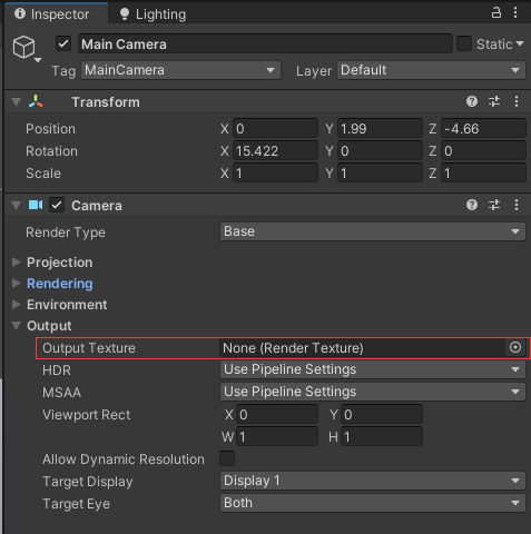
You can specify output to RenderTexture
What is RenderTexture
In U3D, there is a special Texture type called RenderTexture, which essentially connects a FrameBufferObjecrt to a server side Texture object.
What is the texture of server side?
During rendering, Mapping At first, it is stored in the memory of the cpu. This map is usually called the client side texture. It will eventually be sent to the storage of the gpu before the gpu can use it for rendering. The one sent to the gpu is called the server side texture. When copying this tex between cpu and gpu, certain bandwidth bottlenecks should be considered.
What's the use?
We can render some rendering results of the scene to a tex, which can continue to be used. For example, the rearview mirror of a car can be pasted with a rendertex, which is rendered from the camera from this perspective.
Once RenderTex is called and connected to the camera, the output of the camera is no longer presented in the display
code implementation
Here, we have optimized some codes. For example, the step of copying the main camera parameters from CopyFrom is put into the method before rendering, and so is cullingMask. This is because if the main camera parameters are changed or the position is moved during operation, the reflection camera also needs to be changed in real time
[11] Declare an RT graph and make it public so that subsequent shader s can call it
[17]Unity will put the RT graph created by this method into the cache pool. If it is necessary to create an RT graph with the same size information next time, unity will directly use the RT graph in the cache for better performance
[17] The values of the third overload are depth information, including 0 (no depth information), 16 (with depth information) and 32 (depth and Stencil template test)
public class PlaneReflection : MonoBehaviour
{


    public Vector3 T = Vector3.zero;
    public Vector3 R = Vector3.zero;
    public Vector3 S = Vector3.one;

    private Camera reflectionCam;
    public RenderTexture reflectionRT;
    void Start()
    {
        GameObject cam = new GameObject("ReflectionCamera", new System.Type[] { typeof(Camera) });
        reflectionCam = cam.GetComponent<Camera>();

        reflectionRT = RenderTexture.GetTemporary(Screen.width, Screen.height, 0);
        reflectionRT.name = "ReflectionRT";
        RenderPipelineManager.beginCameraRendering += OnBeginCameraRendering;

    }

    void OnBeginCameraRendering(ScriptableRenderContext context, Camera camera)
    {
        if (camera == reflectionCam)
        {
            camera.CopyFrom(Camera.main);
            camera.clearFlags = CameraClearFlags.SolidColor;
            camera.backgroundColor = Color.clear;
            camera.targetTexture = reflectionRT;
            camera.cullingMask = LayerMask.GetMask("Reflection");
            GL.invertCulling = true;

            // Method 2: exposure parameters
            camera.worldToCameraMatrix = Matrix4x4.TRS(T, Quaternion.Euler(R), S) * Camera.main.worldToCameraMatrix;


        }
        else
        {
            GL.invertCulling = false;
        }

    }


}
Everything is ready. I only owe Shader
Get RT diagram
First, we need to solve the problem - how to make the Shader get the RT diagram in the script?
Very simply, you only need such a line of statement in the Start method of the script
The string in the [4] method is our custom attribute name. It is obvious that this method is called in the RT diagram and needs to be called in the class of RT diagram.
void Start()
    {

        reflectionRT.SetGlobalShaderProperty("_ReflectionRT");

    }
At this point, the Shader can directly obtain and sample RT graphs
You don't need to declare it in Properties. You can directly declare the sampler and sample the output
Note that we need to use screen coordinates as UV s
Shader "Unlit/SimpleUnlit"
{
    Properties
    {

    }
    SubShader
    {
        Tags
        {
            "RenderPipeline"="UniversalPipeline"
            "RenderType"="Transparent"
            "UniversalMaterialType" = "Unlit"
            "Queue"="Transparent"
        }
        Pass
        {
            Blend SrcAlpha OneMinusSrcAlpha

            HLSLPROGRAM

            #pragma target 4.5
            #pragma exclude_renderers gles gles3 glcore
            #pragma multi_compile_instancing
            #pragma multi_compile_fog
            #pragma multi_compile _ DOTS_INSTANCING_ON
            #pragma vertex vert
            #pragma fragment frag

            #include "Packages/com.unity.render-pipelines.core/ShaderLibrary/Color.hlsl"
            #include "Packages/com.unity.render-pipelines.core/ShaderLibrary/Texture.hlsl"
            #include "Packages/com.unity.render-pipelines.universal/ShaderLibrary/Core.hlsl"
            #include "Packages/com.unity.render-pipelines.universal/ShaderLibrary/Lighting.hlsl"
            #include "Packages/com.unity.render-pipelines.core/ShaderLibrary/TextureStack.hlsl"
            #include "Packages/com.unity.render-pipelines.universal/ShaderLibrary/ShaderGraphFunctions.hlsl"


            CBUFFER_START(UnityPerMaterial)

            CBUFFER_END

            TEXTURE2D(_ReflectionRT);
            #define smp SamplerState_Linear_Repeat
            SAMPLER(smp);


            struct Attributes
            {
                float3 positionOS : POSITION;
                float2 uv : TEXCOORD;
            };

            struct Varyings
            {
                float4 positionCS : SV_POSITION;
                float2 uv : TEXCOORD;
            };

            Varyings vert(Attributes v)
            {
                Varyings o = (Varyings)0;
                o.positionCS = TransformObjectToHClip(v.positionOS);
                o.uv = v.uv;
                return o;
            }

            half4 frag(Varyings i) : SV_TARGET
            {
                float2 screenUV = i.positionCS.xy/_ScaledScreenParams;
                half4 mainTex = SAMPLE_TEXTURE2D(_ReflectionRT,smp,screenUV);
                return mainTex;
            }

            ENDHLSL
        }

    }

}
Reflection matrix transformation (advanced version)
Basic principle and formula derivation
Considering that simply using flipped images will still bring many problems, let's do it in a different way
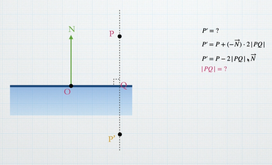
Suppose this is a side view of the reflection plane, N is the normal direction, O is the plane origin, P is the vertex of the reflected object, and P 'is the vertex position after reflection, then in order to find the position of P', we have

Vector N is the direction and PQ is the length
And only | PQ | is unknown. Next, we ask for the specific value of | PQ |
First, connect the PO to get a  horn
horn
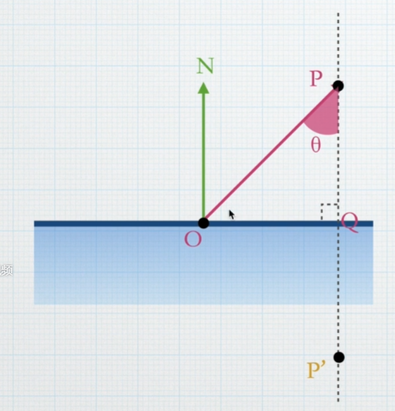
We know:


For the time being, let's plot OP and N

extract

Hey, we have It's over! Bring it up
 try!
try!

We roughly divide OP because they are both lengths and assume Is the unit vector, that is, the module length is 1
So you can get it directly

among It can be obtained by P - O, and we'll bring it in

Equivalent to

Let's look again here. The remaining N is our normal vector, O is the origin of the reflection plane, and P is the vertex, which is a constant
Are available or known values
Now we can bring it into the formula at the beginning. That's it

After substitution

Well, now we're going to bring in the specific coordinates of each value. It seems a little troublesome here, but it's not complicated
Also, don't forget that our ultimate goal is to get a reflection matrix
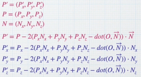
Not enough. Remove it again
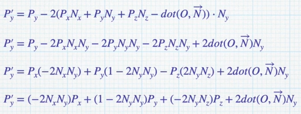
x axis of P '
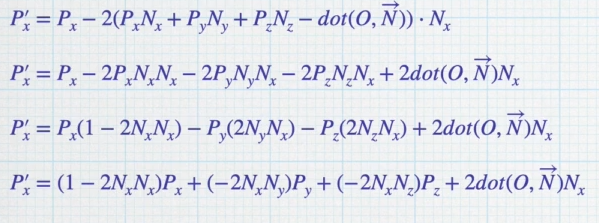
y-axis
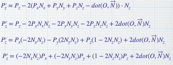
z axis
Finally, write it in matrix like this
The above result is actually the multiplication and addition of the corresponding elements of the row and column of the matrix
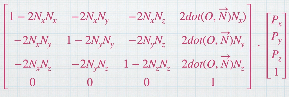
This is our final reflection matrix
Px, py and PZ here are actually the vertex coordinates of the model
code implementation
[14] Declare a 4x4 matrix and fill it in one by one according to the formula
[34] note that the effect will be correct only if the reflection matrix is placed later
 void OnBeginCameraRendering(ScriptableRenderContext context, Camera camera)
    {
        if (camera == reflectionCam)
        {
            camera.CopyFrom(Camera.main);
            camera.clearFlags = CameraClearFlags.SolidColor;
            camera.backgroundColor = Color.clear;
            camera.targetTexture = reflectionRT;
            camera.cullingMask = LayerMask.GetMask("Reflection");
            GL.invertCulling = true;


            // Method 3 (advanced version)
            Matrix4x4 reflectionM = Matrix4x4.identity;
            Vector3 N = new Vector3(0, 1, 0);
            float dotON = Vector3.Dot(transform.position, N);
            reflectionM.m00 = 1 - 2 * N.x * N.x;
            reflectionM.m01 = -2 * N.x * N.y;
            reflectionM.m02 = -2 * N.x * N.z;
            reflectionM.m03 = 2 * dotON * N.x;
            reflectionM.m10 = -2 * N.x * N.y;
            reflectionM.m11 = 1 - 2 * N.y * N.y;
            reflectionM.m12 = -2 * N.y * N.z;
            reflectionM.m13 = 2 * dotON * N.y;
            reflectionM.m20 = -2 * N.x * N.z;
            reflectionM.m21 = -2 * N.y * N.z;
            reflectionM.m22 = 1 - 2 * N.z * N.z;
            reflectionM.m23 = 2 * dotON * N.z;
            reflectionM.m30 = 0;
            reflectionM.m31 = 0;
            reflectionM.m32 = 0;
            reflectionM.m33 = 1;

            camera.worldToCameraMatrix = Camera.main.worldToCameraMatrix * reflectionM;


        }
        else
        {
            GL.invertCulling = false;
        }

    }
Final effect
Some distortions have been made to the RT diagram
