preface
The previous learning is divided into several modular knowledge points. The learned knowledge needs to be combined for practice, and the comprehensive and flexible application ability of the learned MCU knowledge is more investigated. (the writing is relatively basic. If there is any error, please correct it)
task
requirement
- LED brightness can be adjusted and divided into 100 levels;
- If the key is released, when the computer sends a brightness value n (0 < = n < = 100) to the MCU through the serial port, adjust the brightness of the LED to N;
- If the key is pressed, the LED flashes in the form of breathing lamp (not controlled by serial port), with a cycle of 2s;
- while in the main function cannot write any logic
Knowledge points
GPIO output;
External interrupt;
Timer interrupt;
PWM output;
Serial port transceiver
Onboard resources required
LED1;
Key 1;
USB*1
Configuration Engineering
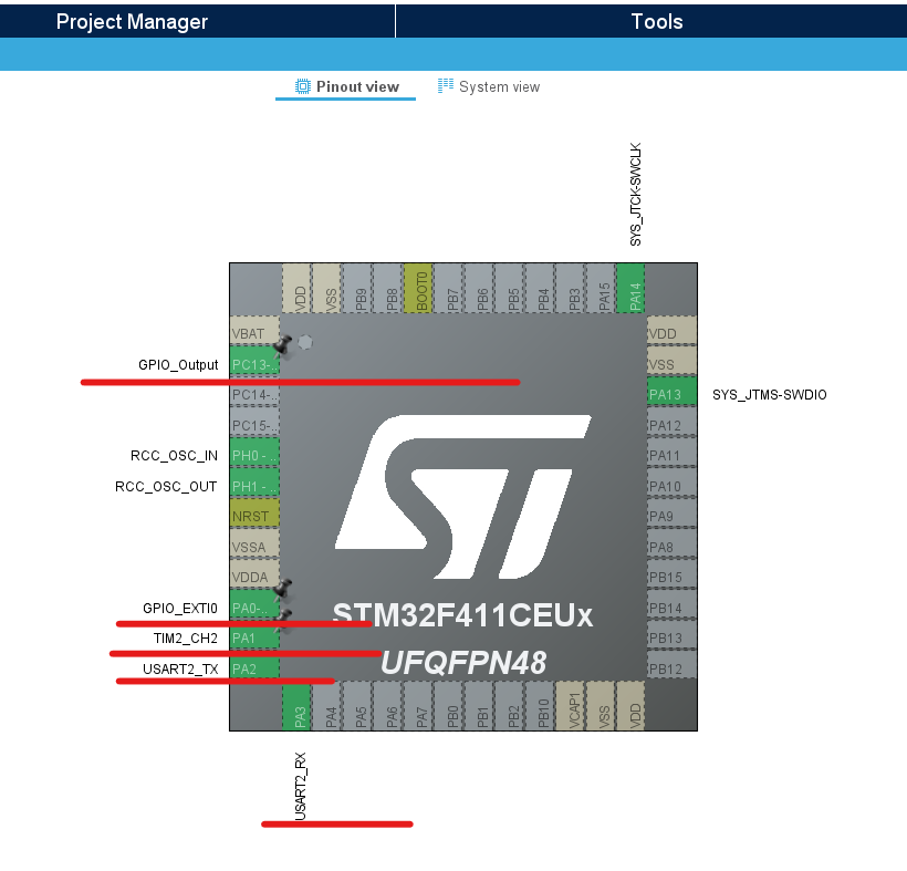
LED light (since PC13 cannot turn on PWM, PC13 pin can be connected with PA1 which can turn on PWM by Du bus on single chip microcomputer):
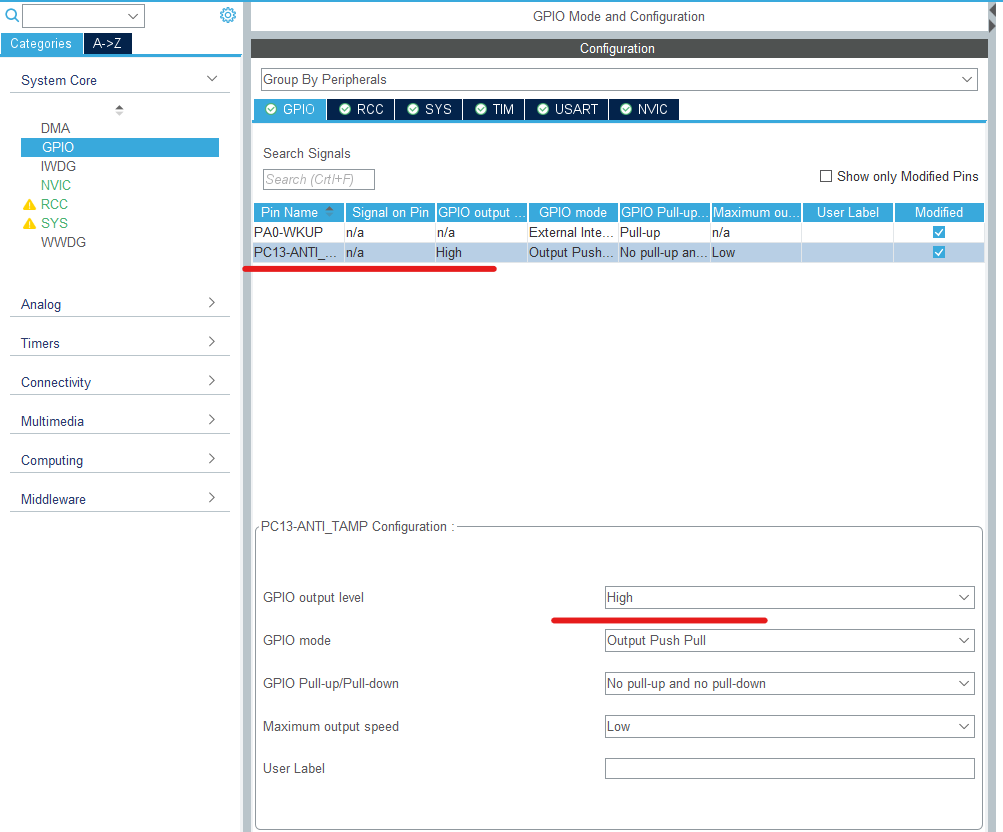
Key:
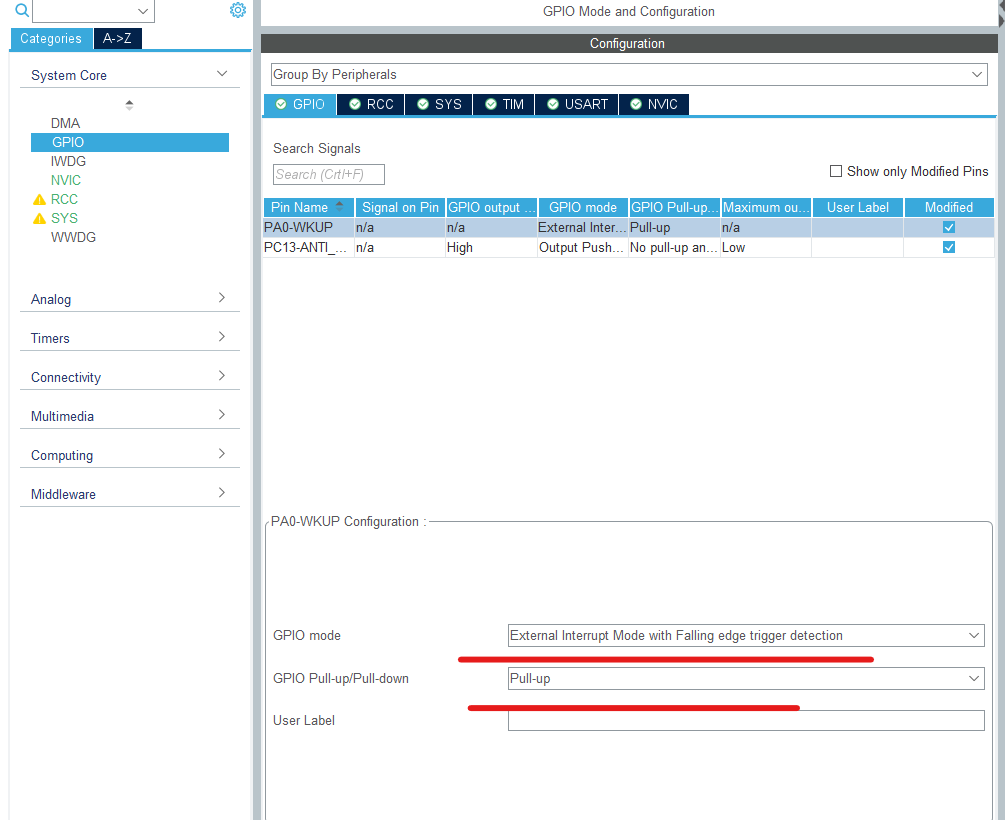
Turn on PWM and set the cycle to 20ms:
Supplement of knowledge points:
PWM mode 1 - when counting up, once timx_ CNT<TIMx_ When CCR1, channel 1 is the effective level (Level 1), otherwise it is the invalid level (level 0); When counting down, once timx_ CNT>TIMx_ When CCR1, channel 1 is invalid level (OC1REF=0), otherwise it is effective level (OC1REF=1). 111: PWM mode 2 - when counting up, once timx_ CNT<TIMx_ When CCR1, channel 1 is invalid level, otherwise it is effective level; When counting down, once timx_ CNT>TIMx_ When CCR1, channel 1 is the effective level, otherwise it is the invalid level.
Valid is 1, invalid is 0
--------
Copyright notice: This article is the original article of CSDN blogger "Mr. Simon", which follows the CC 4.0 BY-SA copyright agreement. Please attach the original source link and this notice for reprint.
Original link: https://blog.csdn.net/qq_35661436/article/details/52734812
Since PC13 is off at high level and invalid level, I use mode 2 here.
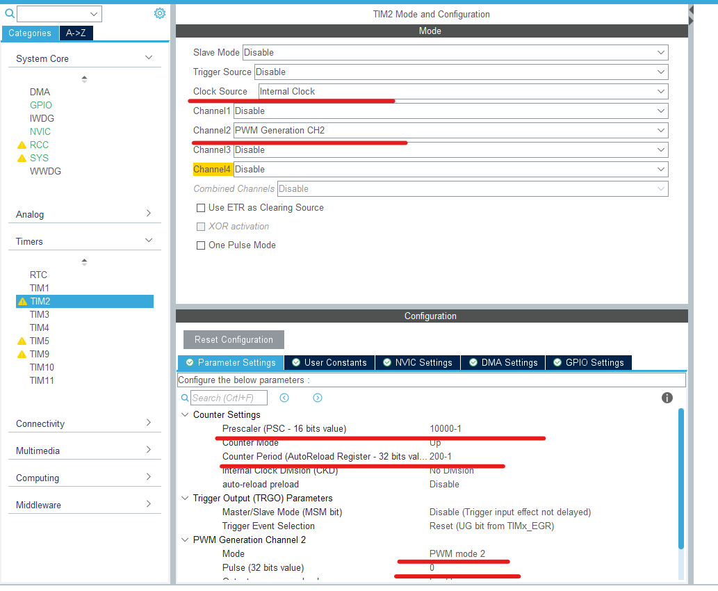
Serial port:
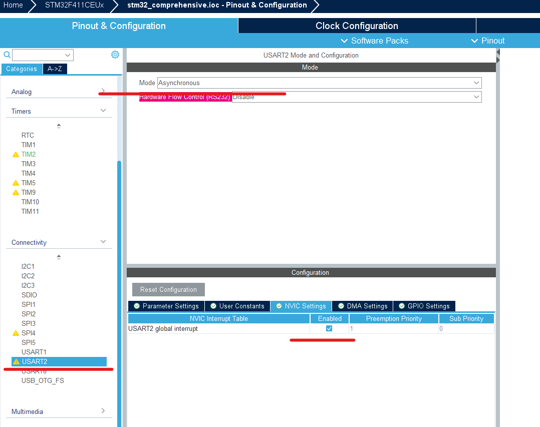
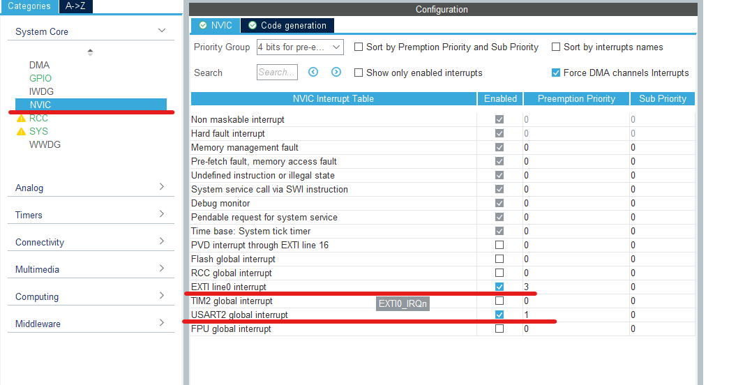
Remember to set interrupt priority:
After completion, the specific pin configuration is shown in the figure:
code
Some contents are reflected in the previous articles. If some parts are not detailed, you can see the corresponding articles before.
/* Private variables ---------------------------------------------------------*/

/* USER CODE BEGIN PV */
uint16_t Duty=0;//Define duty cycle
uint16_t Step=20;//Define step value
uint8_t n[1];//Received value
/* USER CODE END PV */
/* Initialize all configured peripherals */
  MX_GPIO_Init();
  MX_TIM2_Init();
  MX_USART2_UART_Init();
  /* USER CODE BEGIN 2 */
	HAL_UART_Receive_IT(&huart2 ,(uint8_t*)n ,1);//Enable receive interrupt
	HAL_TIM_PWM_Start(&htim2,TIM_CHANNEL_2);//Turn on PWM
  /* USER CODE END 2 */
/* USER CODE BEGIN 4 */
void HAL_UART_RxCpltCallback(UART_HandleTypeDef *huart)//Receive interrupt callback function
{
	if(huart->Instance==USART2)
	{
		if(n[0]>=0&&n[0]<=100)
	  {
			__HAL_TIM_SET_COMPARE (&htim2 ,TIM_CHANNEL_2 ,2*n[0]);//Set duty cycle
			HAL_UART_Transmit(&huart2,n,1,0xFFFFF);//After receiving, send it back to the computer, which can be displayed in the serial port debugging assistant
		}
		HAL_UART_Receive_IT(&huart2,n,1);//Continue to open reception
	}
}
void HAL_GPIO_EXTI_Callback(uint16_t GPIO_Pin)//Interrupt callback function
{
	if(GPIO_Pin==GPIO_PIN_0)
	{
		HAL_Delay(5);
		if(HAL_GPIO_ReadPin (GPIOA,GPIO_PIN_0 )==GPIO_PIN_RESET)//The detection key is pressed
		{
		    //From off to on
			for(Duty =0;Duty <=200;Duty=Duty+Step)
			{
				__HAL_TIM_SET_COMPARE (&htim2 ,TIM_CHANNEL_2 ,Duty );
				HAL_Delay (100);
			}
			//From on to off
			for(Duty =200;Duty > 0;Duty=Duty-Step)
			{
				__HAL_TIM_SET_COMPARE (&htim2 ,TIM_CHANNEL_2 ,Duty );
				HAL_Delay (100);
			}
		}
	}
	HAL_GPIO_EXTI_Callback(GPIO_PIN_0);
}


/* USER CODE END 4 */