Resistance touch experiment based on warship V3
Principle introduction
XPT2046 chip is used in the resistance screen, and its principle is relatively simple: when we touch a certain point, the resistance distribution of X and Y axes will change:
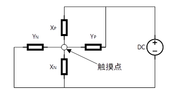
When we touch a point on the next screen, the level of the chip pin will change. At this time, we can read the coordinate data we want after waiting for a period of time.
Chip pin introduction
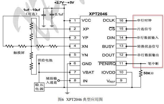
The most important ones here are the pins marked above. The meanings of these pins are as follows:
1. Serial clock: clock signal transmission line
2. Chip selection signal: it is the enable signal, and the low level is effective;
3. Serial data input: write instructions / data to XPT2046 chip;
3. State transition signal: after we transmit the instruction to the chip, the BUSY signal can indicate that the instruction has been received and is being processed. At this time, we need to wait about 6us before we can receive the data;
4. Serial data output: used to output the converted X and Y coordinates;
5. Pen interrupt: it is used to indicate that "the touch screen has been touched". When we read the X and Y coordinates, the pen interrupt signal immediately fails, and the low level of the signal is valid;
In some of our peripheral devices, the level signal transition is generally used to trigger MCU to read the information that the device wants to output. Here, the pen interrupt pin signal of XPT2046 plays this role.
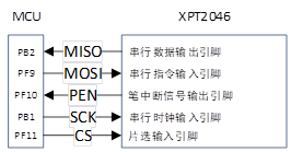
Hardware connection between XPT2046 and MCU
//Resistor / capacitor screen chip connection pin
#definePENPFin(10)//PF10INT pen interrupt signal receiving pin
#defineDOUTPBin(2)//PB2MISO - serial data receiving pin
#defineTDINPFout(9)//PF9MOSI serial command output pin
#defineTCLKPBout(1)//PB1SCLK - serial clock output pin
#defineTCSPFout(11)//PF11CS chip select output pin
The corresponding hardware connection diagram is as follows:
Code parsing
Here, we use GPIO level change to simulate SPI signal, and the specific implementation is as follows:
Structural parameter analysis
//Touch screen controller
typedef struct
{
    u8 (*init)(void);           //Initialize touch screen controller
    u8 (*scan)(u8);             //Scanning touch screen. 0, screen scanning; 1. Physical coordinates;
    void (*adjust)(void);       //Touch screen calibration
    u16 x[CT_MAX_TOUCH];        //Current coordinates
    u16 y[CT_MAX_TOUCH];        //The capacitance screen has up to 5 groups of coordinates, and the resistance screen is represented by x[0],y[0]: during this scanning, the coordinates of the touch screen are stored by x[4],y[4] when pressed for the first time
    u8  sta;                    //Pen status
    //b7: press 1 / release 0;
    //b6:0, no key pressed; 1. Press the key
    //b5: reserved
    //b4~b0: number of points pressed by capacitive touch screen (0 means not pressed, 1 means pressed)
/Touch screen calibration parameters(The capacitive screen does not need calibration)//
    float xfac;
    float yfac;
    short xoff;
    short yoff;
//The new parameter is required when the left and right of the touch screen are completely reversed
//b0:0, vertical screen (suitable for TP with left and right X coordinates and up and down Y coordinates)
//1. Horizontal screen (suitable for TP with left and right Y coordinates and up and down X coordinates)
//b1~6: reserved
//b7:0, resistance screen
//1. Capacitor screen
    u8 touchtype;
} _m_tp_dev;
Here, our screen is a resistance screen, so the saved variables of touch point coordinates are member variables x[4],y[4]; XFAC and yfac are the slope of the primary fitting expression, XOFF and yoff are the offset of the primary fitting expression. In the resistance screen, the meanings of each bit used by the variable sta are as follows:
b6: represents whether there is touch at this time;
b7: represents whether there is an effective touch at this time;
The difference between effective touch and touch: if we keep pressing the touch point, it is equivalent to that we keep touching again, but we think that no matter how long a touch is, it is only an effective touch.
Data write operation
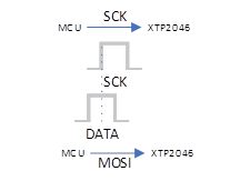
When the information transmitted by MCU to XTP2046 has a rising edge on the signal on the XT92046 serial clock line, XTP2046 stores the level signal on the serial data input line in its own register, which is equivalent to that when a rising edge appears on the clock line, XTP2046 will successfully accept the data. The implementation code is as follows:
//SPI write data
//Write 1byte data to touch screen IC
//num: data to write
voidTP_Write_Byte(u8num)
{
    u8count=0;
    for(count=0;count<8;count++)
    {
        if(num&0x80)TDIN=1;
        else TDIN=0;
        num<<=1;
        TCLK=0;
        delay_us(1);
        TCLK=1;//Rising edge effective
    }
}
The general meaning of the above code is as follows:
1. Set the data bit first, and then simulate the rising edge on the SCK clock line;
2. Continue to cycle until 8 bits are sent.
Read AD conversion results
The instruction of XTP2046 is not complicated. It is nothing more than sending a byte instruction to set the working state of XTP2046, and then XTP2046 will transfer data to MCU after waiting for 6us. This function completes this function. Remember: XTP2046 can only transmit AD conversion results to MCU. We need to perform straight-line fitting to obtain X/Y coordinates (the AD conversion voltage value of X/Y axis and the distance from the origin form a linear relationship of y=kx+b).
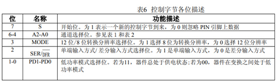
Here, let's focus on what the instruction of this byte contains and what it is used for:
Table 1
| Bit serial number | name |
| 0 | Start bit: S |
| 1 | Address bit: A2 |
| 2 | Address bit: A1 |
| 3 | Address bit: A0 |
| 4 | MODE selection bit: MODE |
| 5 | Control reference source bit: SER=1/DFR=0 |
| 6 | Power down and internal reference voltage configuration bit: PD1 |
| 7 | Power down and internal reference voltage configuration bit: PD0 |
The functions are as follows:
Here we would like to mention that there are two modes of differential input - differential / single ended input. Although the single ended input has high speed and low power consumption, it is vulnerable to external interference. In the section of differential amplifier of mode electricity, we know that when the two pins of the amplifier are differential mode input, the external interference has the same impact on the two pins, Once the difference is made, the external interference signal will be removed, so that the processor can get accurate voltage signal.
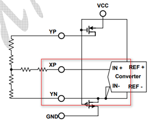
When measuring the Y-axis coordinates, XP is used as the differential input source. At this time, YN input needs to be different from the XP input signal before it can enter the converter. During the analog conversion process, the switch of XP channel should always be on, which will increase some power consumption. The implementation code is as follows:
//SPI read data
//Read adc value from touch screen IC
//CMD: instruction
//Return value: read data
u16 TP_Read_AD(u8 CMD)
{
    u8 count=0;
    u16 Num=0;
    TCLK=0;     //Pull down the clock first
    TDIN=0;     //Pull down the data cable
    TCS=0;      //Select the touch screen IC
    TP_Write_Byte(CMD);//Send command word
    delay_us(6);//The longest conversion time of ADS7846 is 6us=15*0.4us
    TCLK=0;
    delay_us(1);
    TCLK=1;     //Give 1 clock and clear BUSY
    delay_us(1);
    TCLK=0;
    for(count=0; count<16; count++) //Read out 16 bit data, only the upper 12 bits are valid
    {
        Num<<=1;
        TCLK=0; //Falling edge effective
        delay_us(1);
        TCLK=1;
        if(DOUT)Num++;
    }
    Num>>=4;      //Only the upper 12 bits are valid
    TCS=1;      //Release selection
    return(Num);
}
The general flow of code implementation is as follows:
1. Pull down the pins of serial data input line and clock input line (output for MCU) controlling XTP2046;
2. Pull down the CS terminal of chip selection (low level is effective) and select XTP2046. At this time, MCU has established contact with XTP2046;
3. Transfer the 8-bit CMD command to XTP2046;
4. Wait about 6us before MCU receives the returned data from XTP2046. Why do you need to wait for 6us here?
The output AD conversion bits of XTP2046 can be 8 bits / 12 bits, so we will consider according to the maximum output bits. Here, we take num as 16 bits to receive the effective data bits of AD conversion (Note: when set to 12b, only the upper 12 bits of the output 2 bytes are valid). First, the cycle of the clock is 400ns=0.4us:

Then, we need to wait 12 + 3 cycles to read the conversion value, that is, T=15*0.4us=6us:
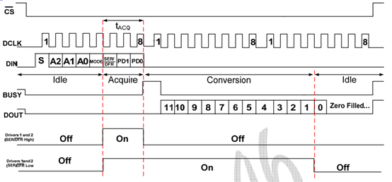
The first 8 clocks are used to input control bytes through the DIN pin. When the converter obtains sufficient information about the next conversion, then set the input multiplexer and reference source input according to the obtained information, and enter the sampling mode. If necessary, the touch panel driver will be started. After 3 multiple clock cycles, the control byte setting is completed and the converter enters the conversion state. At this time, the next 12 clock cycles will complete the real analog-to-digital conversion. In case of metric ratio conversion mode (differential input), the driver will always work during the conversion process, and the 13th clock will output the last bit of the conversion result. The remaining three clock cycles will be used to complete the last byte ignored by the converter (DOUT set low).
be careful:
5. When the returned data format is 12b, we retrieve the high 12 bits of the transmitted data as the data significant bit, and then pull up the chip selection to cut off the connection between MCU and XTP2046 chip.
Here, the reading method we adopt is: input an instruction and receive the returned data. Why is this? Let's take a closer look at the following sequence diagram:
We can see that the two reading cycles overlap, which is equivalent to that when XTP2046 performs AD conversion, we are sending instructions for it to perform ad conversion, and it is impossible for others to send tasks to others before they have completed the task. Therefore, in order to avoid this wrong operation, we operate XTP2046 in the way of "one instruction - > one-time data return".
Algorithm for reading more accurate X/Y axis AD conversion results
The algorithm of "bubble sorting" is used here. Take the XY coordinate results of 5 transformations, remove the maximum and minimum values, and take the average value of XY axis coordinates of the middle 3 times.
//Read a coordinate value (x or y)
//Continuous READ_TIMES secondary data, which are arranged in ascending order
//Then remove the lowest and highest lost_ Number of Vals, average
//xy: instruction (CMD_RDX/CMD_RDY)
//Return value: read data
#define READ_TIMES 5 / / read times
#define LOST_VAL 1 / / discard value
u16 TP_Read_XOY(u8 xy)
{
    u16 i, j;
    u16 buf[READ_TIMES];
    u16 sum=0;
    u16 temp;
    for(i=0; i<READ_TIMES; i++)buf[i]=TP_Read_AD(xy);
    for(i=0; i<READ_TIMES-1; i++) //Sort
    {
        for(j=i+1; j<READ_TIMES; j++)
        {
            if(buf[i]>buf[j])//Ascending arrangement
            {
                temp=buf[i];
                buf[i]=buf[j];
                buf[j]=temp;
            }
        }
    }
    sum=0;
    for(i=LOST_VAL; i<READ_TIMES-LOST_VAL; i++)sum+=buf[i];
    temp=sum/(READ_TIMES-2*LOST_VAL);
    return temp;
}
Use the algorithm to obtain more accurate X/Y axis AD conversion results
//The default is data with touchtype=0
u8 CMD_RDX=0XD0;
u8 CMD_RDY=0X90;
//Read x,y coordinates
//The minimum value cannot be less than 100
//x. Y: read coordinate value
//Return value: 0, failed; 1. Success.
u8 TP_Read_XY(u16 *x,u16 *y)
{
u16 xtemp,ytemp;
xtemp=TP_Read_XOY(CMD_RDX);
ytemp=TP_Read_XOY(CMD_RDY);
//if(xtemp<100||ytemp<100)return 0;// Reading failed
*x=xtemp;
*y=ytemp;
return 1;//Reading successful
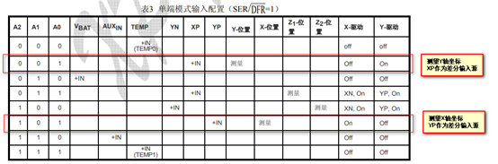
} Here, we want to analyze the instruction CMD_RDX and CMD_ The structure of RDY is as follows:
Table 2
| C7 | C6 | C5 | C4 | C3 | C2 | C1 | C0 | |
| CMD_RDX | 1 | 1 | 0 | 1 | 0 | 0 | 0 | 0 |
| CMD_RDY | 1 | 0 | 0 | 1 | 0 | 0 | 0 | 0 |
The difference between the two is C6~C4 bits, which correspond to A2~A0 address bits respectively:
Determine whether the read X/Y coordinates are qualified and output qualified results
//Read the touch screen IC for 2 consecutive times, and the deviation between these two times shall not exceed
//ERR_RANGE, if the conditions are met, the reading is considered to be correct, otherwise the reading is wrong
//This function can greatly improve the accuracy
//x. Y: read coordinate value
//Return value: 0, failed; 1. Success.
#define ERR_RANGE # 50 / / error range
u8 TP_Read_XY2(u16 *x,u16 *y)
{
    u16 x1,y1;
    u16 x2,y2;
    u8 flag;
    flag=TP_Read_XY(&x1,&y1);
    if(flag==0)return(0);
    flag=TP_Read_XY(&x2,&y2);
    if(flag==0)return(0);
    if(((x2<=x1&&x1<x2+ERR_RANGE)||(x1<=x2&&x2<x1+ERR_RANGE))//The first and second samples are within + - 50
            &&((y2<=y1&&y1<y2+ERR_RANGE)||(y1<=y2&&y2<y1+ERR_RANGE)))
    {
        *x=(x1+x2)/2;
        *y=(y1+y2)/2;
        return 1;
    } else return 0;
}
This function is used to detect whether the deviation between the AD conversion values of X/Y axis detected for two consecutive times is within the allowable error range. If so, it returns the average value of X/Y coordinates read twice; If not, 0 is returned.
Key scan
The disadvantage of the resistance screen is that it needs to be calibrated. Why to calibrate: because we don't know the position of the touch screen and the result of AD conversion value, although the output ad voltage value of X/Y axis has a linear relationship with the distance Xd/Yd between the touch point and the origin on X/Y axis, K and B in y=kx+b equation are still undetermined coefficients. Method for determining undetermined coefficient:
Two points determine a straight line. Therefore, we first measure the voltage value of AD conversion output from two touch points as the dependent variable, and then fit the linear relationship of y=kx+b exclusive to the X/Y axis of the straight line according to Xd/Yd (as the independent variable) between the two points.
Physical coordinates: there is no A/D conversion voltage value before fitting;
Screen coordinates: X/Y coordinate values obtained by fitting;
//Touch key scan
//tp:0, screen coordinates; 1. Physical coordinates (for calibration and other special fields)
//Return value: current touch screen status
//0, no touch on the touch screen; 1. The touch screen has touch
u8 TP_Scan(u8 tp)
{
    if(PEN==0)//A key is pressed
    {
        if(tp)TP_Read_XY2(&tp_dev.x[0],&tp_dev.y[0]);//Read physical coordinates
        else if(TP_Read_XY2(&tp_dev.x[0],&tp_dev.y[0]))//Read screen coordinates
        {
            tp_dev.x[0]=tp_dev.xfac*tp_dev.x[0]+tp_dev.xoff;//Convert results to screen coordinates
            tp_dev.y[0]=tp_dev.yfac*tp_dev.y[0]+tp_dev.yoff;
        }
        if((tp_dev.sta&TP_PRES_DOWN)==0)//Not pressed before
        {
            tp_dev.sta=TP_PRES_DOWN|TP_CATH_PRES;//Press the key
            tp_dev.x[4]=tp_dev.x[0];//Record the coordinates at the first press
            tp_dev.y[4]=tp_dev.y[0];
        }
    } else
    {
        if(tp_dev.sta&TP_PRES_DOWN)//It was pressed before
        {
            tp_dev.sta&=~(1<<7);//Mark key release
        } else//It hasn't been pressed before
        {
            tp_dev.x[4]=0;
            tp_dev.y[4]=0;
            tp_dev.x[0]=0xffff;
            tp_dev.y[0]=0xffff;
        }
    }
    return tp_dev.sta&TP_PRES_DOWN;//Return to the current touch screen status
}
Note: no matter how long, touching the display screen is only equivalent to one touch.
The general execution process of the above procedures is as follows:
1. If a key is pressed (pen interrupt signal PEN=0, pen interrupt signal low level is valid), when the input parameter tp=1, the resistance screen only reads the ad voltage value of X/Y axis and does not carry out X/Y axis coordinate fitting (mainly at this time, the determination principle of "two points determine a straight line" is not used to determine the undetermined coefficient k,b, which is nothing); On the contrary, if the parameter tp=0, the AD conversion value of X/Y axis is measured, and the coordinates of the actual touch point in X/Y axis are solved according to the solved undetermined coefficients K and B;
2. If a key is pressed (pen interrupt signal PEN=0, pen interrupt signal low level is valid), if it has not been touched before, it indicates that this touch is valid, mark that the touch screen has been touched and record the calculated X/Y coordinates;
3. If the pen interrupt signal PEN=1 and the key is pressed, it means that the display screen has been touched for a long time. At this time, we mark "the touch screen has not been touched again"; When we fully release the display, the information in the X/Y coordinate variable used to save the touch point is cleared.
① How to ensure that you only act according to the touch for a long time?
1. If the touch flag bit is always valid, but the pen interrupt signal is invalid, Description: the effective touch times is 1, execute the following procedure:
if(tp_dev.sta&TP_PRES_DOWN)//It was pressed before
{
    tp_dev.sta&=~(1<<7);//Mark key release
}
2. If the touch flag bit is invalid and the pen interrupt signal is invalid, Description: at this time, the touch screen is not touched, execute the following procedures:
tp_dev.x[4]=0;
tp_dev.y[4]=0;
tp_dev.x[0]=0xffff;
tp_dev.y[0]=0xffff;
This program is used to clear the variables used to record the X/Y coordinates and the intermediate variables used to calculate the X/Y coordinates.
Note that the X/Y coordinate of the touch point is assigned to the variable only at the first touch, that is, a valid touch:
if((tp_dev.sta&TP_PRES_DOWN)==0)//Not pressed before
{
    tp_dev.sta=TP_PRES_DOWN|TP_CATH_PRES;//Press the key
    tp_dev.x[4]=tp_dev.x[0];//Record the coordinates at the first press
    tp_dev.y[4]=tp_dev.y[0];
}
b7 of sta is set to one only when the LCD is touched for the first time, and the others are 0, that is, only the first touch is an effective touch. The X/Y coordinates of the touch point at this time will be recorded only when it is effectively touched. The return value of the scan function is "whether it is a valid touch. If yes, it returns true, and if not, it returns 0":
return tp_dev.sta&TP_PRES_DOWN;//Return to the current touch screen status
② What is the meaning of the input parameter tp?
if(tp)TP_Read_XY2(&tp_dev.x[0],&tp_dev.y[0]);//Read physical coordinates
else if(TP_Read_XY2(&tp_dev.x[0],&tp_dev.y[0]))//Read screen coordinates
{
    tp_dev.x[0]=tp_dev.xfac*tp_dev.x[0]+tp_dev.xoff;//Convert results to screen coordinates
    tp_dev.y[0]=tp_dev.yfac*tp_dev.y[0]+tp_dev.yoff;
}
The meaning of tp is to determine whether to read only the A/D conversion value (for calibration) or read the A/D conversion value and fit the actual coordinates of X/Y.
Storage of calibration data
//The base address of the address interval stored in EEPROM occupies 14 bytes (RANGE:SAVE_ADDR_BASE~SAVE_ADDR_BASE+13)
#define SAVE_ADDR_BASE 40
//Save calibration parameters
void TP_Save_Adjdata(void)
{
    AT24CXX_Write(SAVE_ADDR_BASE,(u8*)&tp_dev.xfac,14); //Force save & TP_ The 14 bytes of data starting from the dev.xfac address are saved to tp_dev.touchtype
    AT24CXX_WriteOneByte(SAVE_ADDR_BASE+14,0X0A);       //At the end, write 0X0A mark and calibrate it
}
Why is the offset of the data stored here 0 ~ 14? It depends on the storage address of the data we want to save in the defined structure:
//Touch screen controller
typedef struct
{
    u8 (*init)(void);           //Initialize touch screen controller
    u8 (*scan)(u8);             //Scanning touch screen. 0, screen scanning; 1. Physical coordinates;
    void (*adjust)(void);       //Touch screen calibration
    u16 x[CT_MAX_TOUCH];        //Current coordinates
    u16 y[CT_MAX_TOUCH];        //The capacitance screen has up to 5 groups of coordinates, and the resistance screen is represented by x[0],y[0]: during this scanning, the coordinates of the touch screen are stored by x[4],y[4] when pressed for the first time
    u8  sta;                    //Pen status
    //b7: press 1 / release 0;
    //b6:0, no key pressed; 1. Press the key
    //b5: reserved
    //b4~b0: number of points pressed by capacitive touch screen (0 means not pressed, 1 means pressed)
/Touch screen calibration parameters(The capacitive screen does not need calibration)//
    float xfac;
    float yfac;
    short xoff;
    short yoff;
//The new parameter is required when the left and right of the touch screen are completely reversed
//b0:0, vertical screen (suitable for TP with left and right X coordinates and up and down Y coordinates)
//1. Horizontal screen (suitable for TP with left and right Y coordinates and up and down X coordinates)
//b1~6: reserved
//b7:0, resistance screen
//1. Capacitor screen
    u8 touchtype;
} _m_tp_dev;
Here, the variables we want to save are XFAC, yfac, XOFF and yoff, which can respectively fit the relationship between X/Y coordinates and the voltage value obtained from X/Y axis A/D conversion:
Y axis: y = yfac*x+yoff;
X axis: x = xfac*x+xoff;
14 bytes of data are saved here:
//Start writing the specified number of data at the specified address in AT24CXX
//WriteAddr: the address to start writing is 0 ~ 255 for 24c02
//pBuffer: first address of data array
//NumToWrite: number of data to write
void AT24CXX_Write(u16 WriteAddr,u8 *pBuffer,u16 NumToWrite)
{
    while(NumToWrite--)
    {
        AT24CXX_WriteOneByte(WriteAddr,*pBuffer);
        WriteAddr++;
        pBuffer++;
    }
}
The code shows that 24C02 saves NumToWrite data, because when NumToWrite is reduced to 0, it will automatically jump out of the cycle, so it saves the 14 byte data of byte sequence number: 14 ~ 1.
In_ m_ tp_ In the dev structure, the address of yoff is offset by 12 bytes compared with the address of xfac. The address distribution of each variable is as follows:
Table 3
| Variable name | Starting address (address relative to xfac) | Termination address (address relative to xfac) |
| xfac | 0 | 3 |
| yfac | 4 | 7 |
| xoff | 8 | 9 |
| yoff | 10 | 11 |
| touchtype | 11 | 12 |
| Tag variable | 14 | 14 |
Note: in STM32, float occupies 4 bytes and short occupies 2 bytes. Here, the marked variable is a sign indicating whether it has been calibrated.
Read the undetermined coefficient required by the primary linear fitting of X/Y axis
//Get the calibration value stored in EEPROM
//Return value: 1. The data is obtained successfully
//0, acquisition failed, recalibrate
u8 TP_Get_Adjdata(void)
{
    u8 temp;
    temp=AT24CXX_ReadOneByte(SAVE_ADDR_BASE+14);//Read the marking word to see if it has been calibrated!
    if(temp==0X0A)//The touch screen has been calibrated
    {
        AT24CXX_Read(SAVE_ADDR_BASE,(u8*)&tp_dev.xfac,14);//Read the previously saved calibration data
        if(tp_dev.touchtype)//10. The Y direction is opposite to the screen
        {
            CMD_RDX=0X90;
            CMD_RDY=0XD0;
        } else                 //10. The Y direction is the same as the screen
        {
            CMD_RDX=0XD0;
            CMD_RDY=0X90;
        }
        return 1;
    }
    return 0;
}
The execution process of the program is as follows:
1. Read out the calibration parameters (pending parameters kx/ky,dx/dy required for X/Y axis fitting) stored in 24C02;
2. Then, mark the variable TP according to the horizontal and vertical screen_ Dev.touchtype. In fact, the essence of the horizontal and vertical screen is to load the coordinate values of X-axis fitting into the array used to store the coordinate values of Y-axis fitting, that is, into tp_dev.y[CT_MAX_TOUCH]; On the contrary, the X-axis fitting coordinate value is loaded into the array used to store the X-axis fitting coordinate value, that is, stored in tp_dev.x[CT_MAX_TOUCH].
LCD display
//Functions related to LCD part
//Draw a touch point
//For calibration
//x. Y: coordinates
//Color: color
void TP_Drow_Touch_Point(u16 x,u16 y,u16 color)
{
    POINT_COLOR=color;
    LCD_DrawLine(x-12,y,x+13,y);//Horizontal line
    LCD_DrawLine(x,y-12,x,y+13);//Vertical line
    LCD_DrawPoint(x+1,y+1);
    LCD_DrawPoint(x-1,y+1);
    LCD_DrawPoint(x+1,y-1);
    LCD_DrawPoint(x-1,y-1);
    LCD_Draw_Circle(x,y,6);//Draw the center circle
}
The above program displays the following graphics at the (x,y) coordinate position in TFTLCD:
Draw point function
//Draw a large point (2 * 2 point)
//x. Y: coordinates
//Color: color
void TP_Draw_Big_Point(u16 x,u16 y,u16 color)
{
    POINT_COLOR=color;
    LCD_DrawPoint(x,y);//Center point
    LCD_DrawPoint(x+1,y);
    LCD_DrawPoint(x,y+1);
    LCD_DrawPoint(x+1,y+1);
}
The above program displays the following graphics at the (x,y) coordinate position in TFTLCD:
Calculation and storage of calibration / undetermined coefficients
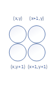
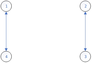
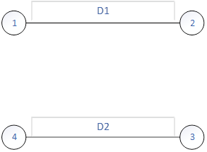
1. We need to specify four known coordinate points, and then we touch these four points to obtain the A/D conversion value of the actual X/Y axis of the touch points returned by XPT2046, so as to calculate the difference of A/D conversion values between intersections:
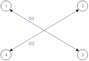
Then, in the ideal state, D1/D2 should be 1, but it backfires. We stipulate that as long as D1/D2 is within [0.95, 1.05], we consider the fitting coefficient calculated by using these four points to be qualified.
//Equal opposite sides
tem1=abs(pos_temp[0][0]-pos_temp[1][0]);//x1-x2
tem2=abs(pos_temp[0][1]-pos_temp[1][1]);//y1-y2
tem1*=tem1;
tem2*=tem2;
d1=sqrt(tem1+tem2);//Get the distance of 1,2

tem1=abs(pos_temp[2][0]-pos_temp[3][0]);//x3-x4
tem2=abs(pos_temp[2][1]-pos_temp[3][1]);//y3-y4
tem1*=tem1;
tem2*=tem2;
d2=sqrt(tem1+tem2);//Get the distance of 3,4
fac=(float)d1/d2;
if(fac<0.95||fac>1.05||d1==0||d2==0)//Unqualified
{
    cnt=0;
    TP_Drow_Touch_Point(lcddev.width-20,lcddev.height-20,WHITE);    //Clear point 4
    TP_Drow_Touch_Point(20,20,RED);                             //Draw point 1
    TP_Adj_Info_Show(pos_temp[0][0],pos_temp[0][1],pos_temp[1][0],pos_temp[1][1],pos_temp[2][0],pos_temp[2][1],pos_temp[3][0],pos_temp[3][1],fac*100);//Display data
 }
2. We need to specify four known coordinate points, and then we touch these four points to obtain the A/D conversion value of the actual X/Y axis of the touch points returned by XPT2046, so as to calculate the difference of A/D conversion values between intersections:
Then, in the ideal state, D1/D2 should be 1, but it backfires. We stipulate that as long as D1/D2 is within [0.95, 1.05], we consider the fitting coefficient calculated by using these four points to be qualified.
tem1=abs(pos_temp[0][0]-pos_temp[2][0]);//x1-x3
tem2=abs(pos_temp[0][1]-pos_temp[2][1]);//y1-y3
tem1*=tem1;
tem2*=tem2;
d1=sqrt(tem1+tem2);//Get the distance of 1,3

tem1=abs(pos_temp[1][0]-pos_temp[3][0]);//x2-x4
tem2=abs(pos_temp[1][1]-pos_temp[3][1]);//y2-y4
tem1*=tem1;
tem2*=tem2;
d2=sqrt(tem1+tem2);//Get the distance of 2,4
fac=(float)d1/d2;
if(fac<0.95||fac>1.05)//Unqualified
{
    cnt=0;
    TP_Drow_Touch_Point(lcddev.width-20,lcddev.height-20,WHITE);    //Clear point 4
    TP_Drow_Touch_Point(20,20,RED);                             //Draw point 1
    TP_Adj_Info_Show(pos_temp[0][0],pos_temp[0][1],pos_temp[1][0],pos_temp[1][1],pos_temp[2][0],pos_temp[2][1],pos_temp[3][0],pos_temp[3][1],fac*100);//Display data
    continue;
}//Right
3. We need to specify four known coordinate points, and then we touch these four points to obtain the A/D conversion value of the actual X/Y axis of the touch point returned by XPT2046, so as to calculate the difference of A/D conversion value between the intersection points:
Then, in the ideal state, D1/D2 should be 1, but it backfires. We stipulate that as long as D1/D2 is within [0.95, 1.05], we consider the fitting coefficient calculated by using these four points to be qualified.
//Diagonal equality
tem1=abs(pos_temp[1][0]-pos_temp[2][0]);//x1-x3
tem2=abs(pos_temp[1][1]-pos_temp[2][1]);//y1-y3
tem1*=tem1;
tem2*=tem2;
d1=sqrt(tem1+tem2);//Get the distance of 1,4

tem1=abs(pos_temp[0][0]-pos_temp[3][0]);//x2-x4
tem2=abs(pos_temp[0][1]-pos_temp[3][1]);//y2-y4
tem1*=tem1;
tem2*=tem2;
d2=sqrt(tem1+tem2);//Get the distance of 2,3
fac=(float)d1/d2;
if(fac<0.95||fac>1.05)//Unqualified
{
    cnt=0;
    TP_Drow_Touch_Point(lcddev.width-20,lcddev.height-20,WHITE);    //Clear point 4
    TP_Drow_Touch_Point(20,20,RED);                             //Draw point 1
    TP_Adj_Info_Show(pos_temp[0][0],pos_temp[0][1],pos_temp[1][0],pos_temp[1][1],pos_temp[2][0],pos_temp[2][1],pos_temp[3][0],pos_temp[3][1],fac*100);//Display data
    continue;
}//Right
4. After we calculate the above three cases, if all the requirements are met, we think that the coordinates of the touch point returned by XPT2046 chip are roughly the coordinates of the target touch point we specify. Then, we use the actual coordinates of the four points to calculate the fitting coefficients KX / KY and DX / dy of the X/Y axis coordinates, and store them in 24C02 to end the polling.
//Calculation results
tp_dev.xfac=(float)(lcddev.width-40)/(pos_temp[1][0]-pos_temp[0][0]);//Get xfac
tp_dev.xoff=(lcddev.width-tp_dev.xfac*(pos_temp[1][0]+pos_temp[0][0]))/2;//Get xoff

tp_dev.yfac=(float)(lcddev.height-40)/(pos_temp[2][1]-pos_temp[0][1]);//Get yfac
tp_dev.yoff=(lcddev.height-tp_dev.yfac*(pos_temp[2][1]+pos_temp[0][1]))/2;//Get yoff
if(abs(tp_dev.xfac)>2||abs(tp_dev.yfac)>2)//The touch screen is the opposite of the preset
{
    cnt=0;
    TP_Drow_Touch_Point(lcddev.width-20,lcddev.height-20,WHITE);    //Clear point 4
    TP_Drow_Touch_Point(20,20,RED);                             //Draw point 1
    LCD_ShowString(40,26,lcddev.width,lcddev.height,16,"TP Need readjust!");
    tp_dev.touchtype=!tp_dev.touchtype;//Modify the touch screen type
    if(tp_dev.touchtype)//10. The Y direction is opposite to the screen
    {
        CMD_RDX=0X90;
        CMD_RDY=0XD0;
    } else                 //10. The Y direction is the same as the screen
    {
        CMD_RDX=0XD0;
        CMD_RDY=0X90;
    }
    continue;
}
POINT_COLOR=BLUE;
LCD_Clear(WHITE);//Clear screen
LCD_ShowString(35,110,lcddev.width,lcddev.height,16,"Touch Screen Adjust OK!");//Correction complete
delay_ms(1000);
TP_Save_Adjdata();
LCD_Clear(WHITE);//Clear screen
return;//Correction complete
The maximum polling is 1000 times. If 1000 times of polling is still unqualified, read out the data in 24C02 and assign it to the variable used for fitting.
delay_ms(10);
outtime++;
if(outtime>1000)
{
    TP_Get_Adjdata();
    break;
}
MCU pin initialization
//Touch screen initialization
//Return value: 0, no calibration
//1. Calibrated
u8 TP_Init(void)
{
    GPIO_InitTypeDef  GPIO_InitStructure;

    //Note that the GPIO operation is not effective until the clock is enabled
    //Therefore, the clock must be enabled before pulling up In order to realize the real pull-up output

    RCC_APB2PeriphClockCmd(RCC_APB2Periph_GPIOB|RCC_APB2Periph_GPIOF, ENABLE);   //Enable PB,PF port clock

    GPIO_InitStructure.GPIO_Pin = GPIO_Pin_1;                //PB1 port configuration
    GPIO_InitStructure.GPIO_Mode = GPIO_Mode_Out_PP;         //Push pull output
    GPIO_InitStructure.GPIO_Speed = GPIO_Speed_50MHz;
    GPIO_Init(GPIOB, &GPIO_InitStructure);//B1 push pull output
    GPIO_SetBits(GPIOB,GPIO_Pin_1);//Pull up

    GPIO_InitStructure.GPIO_Pin = GPIO_Pin_2;                //PB2 port configuration
    GPIO_InitStructure.GPIO_Mode = GPIO_Mode_IPU;        //Pull up input
    GPIO_Init(GPIOB, &GPIO_InitStructure);//B2 pull-up input
    GPIO_SetBits(GPIOB,GPIO_Pin_2);//Pull up

    GPIO_InitStructure.GPIO_Pin = GPIO_Pin_11|GPIO_Pin_9;                //F9, PF11 port configuration
    GPIO_InitStructure.GPIO_Mode = GPIO_Mode_Out_PP;         //Push pull output
    GPIO_InitStructure.GPIO_Speed = GPIO_Speed_50MHz;
    GPIO_Init(GPIOF, &GPIO_InitStructure);//PF9,PF11 push-pull output
    GPIO_SetBits(GPIOF, GPIO_Pin_11|GPIO_Pin_9);//Pull up

    GPIO_InitStructure.GPIO_Pin = GPIO_Pin_10;               //PF10 port configuration
    GPIO_InitStructure.GPIO_Mode = GPIO_Mode_IPU;        //Pull up input
    GPIO_Init(GPIOF, &GPIO_InitStructure);//PF10 pull-up input
    GPIO_SetBits(GPIOF,GPIO_Pin_10);//Pull up

    TP_Read_XY(&tp_dev.x[0],&tp_dev.y[0]);//First read initialization
    AT24CXX_Init();         //Initialize 24CXX
    if(TP_Get_Adjdata())return 0;//Calibrated
    else                    //Uncalibrated?
    {
        LCD_Clear(WHITE);   //Clear screen
        TP_Adjust();        //Screen calibration
    }
    TP_Get_Adjdata();
    return 1;
}
This step is to initialize some pins, and call the calibration function to calculate and save the calibration value. Calibrated returns 0 / uncalibrated returns 1.