Robot introduction
The robot consists of four parts: control system (brain), sensing system (eyes), driving system (muscle) and execution system (hand).
Sensor input signal, the control system receives and releases the control command, drives the control command into a signal that can be executed by the execution system, and the execution system executes.
modeling
URDF unified Robot Description Format - unified robot format. ROS can parse the robot model described in XML format in URDF file.
In URDF file, the components of robot can be roughly divided into two categories: joint and link.
link describes the appearance and physical properties of a rigid body: appearance parameters: size, color, shape. Inertia parameter: inertia matrix. Collision attributes: collision parameters.
Joint describes the kinematic and dynamic properties of a joint, including the position and speed limits of the joint. It can be divided into six categories: continuous, revolve, prismatic, planar, floating and fixed. They all have their own scope of use. In particular, continuous rotating joints are unrestricted, and wheels and revolve are restricted. These two types are often used.
Create a functional package for robot modeling - implement a simple URDF model:
catkin_create_pkg mbot_description urdf xacro
Robot name_ description is a conventional model file representing the robot, which is dependent on two function packages.
No longer in a feature pack cpp files, all folders. Create four folders: urdf (specific model file for placing the robot), meshes (appearance texture file for placing the robot), create a launch folder to start, and a config folder to configure.
(1) Write display under the luanch folder_ mbot_ base_ urdf. Launch is used for more convenient startup.
<launch>
	<param name="robot_description" textfile="$(find mbot_description)/urdf/mbot_base.urdf" />

	<!-- set up GUI Parameters, display joint control plug-in -->
	<param name="use_gui" value="true"/>

	<!-- function joint_state_publisher Node to publish the joint state of the robot  -->
	<node name="joint_state_publisher" pkg="joint_state_publisher" type="joint_state_publisher" />

	<!-- function robot_state_publisher Nodes, publishing tf  -->
	<node name="robot_state_publisher" pkg="robot_state_publisher" type="state_publisher" />

	<!-- function rviz Visual interface -->
	<node name="rviz" pkg="rviz" type="rviz" args="-d $(find mbot_description)/config/mbot_urdf.rviz" required="true" />
</launch>
(2) Create mBot under urdf folder_ base. The urdf file (the model of the base) is used for modeling.
In the experiment, you can adjust the parameters to see what changes there are to promote the understanding of the significance of each parameter.
<?xml version="1.0" ?>
<robot name="mbot">

    <link name="base_link">
        <visual>
            <origin xyz=" 0 0 0" rpy="0 0 0" />
            <geometry>
                <cylinder length="0.16" radius="0.20"/>
            </geometry>
            <material name="yellow">
                <color rgba="1 0.4 0 1"/>
            </material>
        </visual>
    </link>

    <joint name="left_wheel_joint" type="continuous">
        <origin xyz="0 0.19 -0.05" rpy="0 0 0"/>
        <parent link="base_link"/>
        <child link="left_wheel_link"/>
        <axis xyz="0 1 0"/>
    </joint>

    <link name="left_wheel_link">
        <visual>
            <origin xyz="0 0 0" rpy="1.5707 0 0" />
            <geometry>
                <cylinder radius="0.06" length = "0.025"/>
            </geometry>
            <material name="white">
                <color rgba="1 1 1 0.9"/>
            </material>
        </visual>
    </link>

    <joint name="right_wheel_joint" type="continuous">
        <origin xyz="0 -0.19 -0.05" rpy="0 0 0"/>
        <parent link="base_link"/>
        <child link="right_wheel_link"/>
        <axis xyz="0 1 0"/>
    </joint>

    <link name="right_wheel_link">
        <visual>
            <origin xyz="0 0 0" rpy="1.5707 0 0" />
            <geometry>
                <cylinder radius="0.06" length = "0.025"/>
            </geometry>
            <material name="white">
                <color rgba="1 1 1 0.9"/>
            </material>
        </visual>
    </link>

    <joint name="front_caster_joint" type="continuous">
        <origin xyz="0.18 0 -0.095" rpy="0 0 0"/>
        <parent link="base_link"/>
        <child link="front_caster_link"/>
        <axis xyz="0 1 0"/>
    </joint>

    <link name="front_caster_link">
        <visual>
            <origin xyz="0 0 0" rpy="0 0 0"/>
            <geometry>
                <sphere radius="0.015" />
            </geometry>
            <material name="black">
                <color rgba="0 0 0 0.95"/>
            </material>
        </visual>
    </link>

    <joint name="back_caster_joint" type="continuous">
        <origin xyz="-0.18 0 -0.095" rpy="0 0 0"/>
        <parent link="base_link"/>
        <child link="back_caster_link"/>
        <axis xyz="0 1 0"/>
    </joint>

    <link name="back_caster_link">
        <visual>
            <origin xyz="0 0 0" rpy="0 0 0"/>
            <geometry>
                <sphere radius="0.015" />
            </geometry>
            <material name="black">
                <color rgba="0 0 0 0.95"/>
            </material>
        </visual>
    </link>

</robot>
(3) Configure rviz in the config folder and create mBot The rviz configuration files are all in the fixed format of rviz and do not need to be understood.
Panels:
  - Class: rviz/Displays
    Help Height: 78
    Name: Displays
    Property Tree Widget:
      Expanded:
        - /Global Options1
        - /Status1
        - /TF1
      Splitter Ratio: 0.5
    Tree Height: 473
  - Class: rviz/Selection
    Name: Selection
  - Class: rviz/Tool Properties
    Expanded:
      - /2D Pose Estimate1
      - /2D Nav Goal1
      - /Publish Point1
    Name: Tool Properties
    Splitter Ratio: 0.588679016
  - Class: rviz/Views
    Expanded:
      - /Current View1
    Name: Views
    Splitter Ratio: 0.5
  - Class: rviz/Time
    Experimental: false
    Name: Time
    SyncMode: 0
    SyncSource: ""
Visualization Manager:
  Class: ""
  Displays:
    - Alpha: 0.5
      Cell Size: 1
      Class: rviz/Grid
      Color: 160; 160; 164
      Enabled: true
      Line Style:
        Line Width: 0.0299999993
        Value: Lines
      Name: Grid
      Normal Cell Count: 0
      Offset:
        X: 0
        Y: 0
        Z: 0
      Plane: XY
      Plane Cell Count: 10
      Reference Frame: <Fixed Frame>
      Value: true
    - Alpha: 1
      Class: rviz/RobotModel
      Collision Enabled: false
      Enabled: true
      Links:
        All Links Enabled: true
        Expand Joint Details: false
        Expand Link Details: false
        Expand Tree: false
        Link Tree Style: Links in Alphabetic Order
        back_castor_link:
          Alpha: 1
          Show Axes: false
          Show Trail: false
          Value: true
        base_footprint:
          Alpha: 1
          Show Axes: false
          Show Trail: false
          Value: true
        base_link:
          Alpha: 1
          Show Axes: false
          Show Trail: false
          Value: true
        front_castor_link:
          Alpha: 1
          Show Axes: false
          Show Trail: false
          Value: true
        left_wheel_link:
          Alpha: 1
          Show Axes: false
          Show Trail: false
          Value: true
        right_wheel_link:
          Alpha: 1
          Show Axes: false
          Show Trail: false
          Value: true
      Name: RobotModel
      Robot Description: robot_description
      TF Prefix: ""
      Update Interval: 0
      Value: true
      Visual Enabled: true
    - Class: rviz/TF
      Enabled: true
      Frame Timeout: 15
      Frames:
        All Enabled: true
        back_castor_link:
          Value: true
        base_footprint:
          Value: true
        base_link:
          Value: true
        front_castor_link:
          Value: true
        left_wheel_link:
          Value: true
        right_wheel_link:
          Value: true
      Marker Scale: 0.100000001
      Name: TF
      Show Arrows: true
      Show Axes: true
      Show Names: true
      Tree:
        base_footprint:
          base_link:
            back_castor_link:
              {}
            front_castor_link:
              {}
            left_wheel_link:
              {}
            right_wheel_link:
              {}
      Update Interval: 0
      Value: true
  Enabled: true
  Global Options:
    Background Color: 48; 48; 48
    Default Light: true
    Fixed Frame: base_footprint
    Frame Rate: 30
  Name: root
  Tools:
    - Class: rviz/Interact
      Hide Inactive Objects: true
    - Class: rviz/MoveCamera
    - Class: rviz/Select
    - Class: rviz/FocusCamera
    - Class: rviz/Measure
    - Class: rviz/SetInitialPose
      Topic: /initialpose
    - Class: rviz/SetGoal
      Topic: /move_base_simple/goal
    - Class: rviz/PublishPoint
      Single click: true
      Topic: /clicked_point
  Value: true
  Views:
    Current:
      Class: rviz/Orbit
      Distance: 0.86167258
      Enable Stereo Rendering:
        Stereo Eye Separation: 0.0599999987
        Stereo Focal Distance: 1
        Swap Stereo Eyes: false
        Value: false
      Focal Point:
        X: -0.0422003381
        Y: -0.00756526971
        Z: 0.119616583
      Focal Shape Fixed Size: true
      Focal Shape Size: 0.0500000007
      Invert Z Axis: false
      Name: Current View
      Near Clip Distance: 0.00999999978
      Pitch: 0.265398145
      Target Frame: <Fixed Frame>
      Value: Orbit (rviz)
      Yaw: 0.650397897
    Saved: ~
Window Geometry:
  Displays:
    collapsed: false
  Height: 754
  Hide Left Dock: false
  Hide Right Dock: false
  QMainWindow State: 000000ff00000000fd00000004000000000000016a00000268fc0200000008fb0000001200530065006c0065006300740069006f006e00000001e10000009b0000006100fffffffb0000001e0054006f006f006c002000500072006f007000650072007400690065007302000001ed000001df00000185000000a3fb000000120056006900650077007300200054006f006f02000001df000002110000018500000122fb000000200054006f006f006c002000500072006f0070006500720074006900650073003203000002880000011d000002210000017afb000000100044006900730070006c006100790073010000002800000268000000d700fffffffb0000002000730065006c0065006300740069006f006e00200062007500660066006500720200000138000000aa0000023a00000294fb00000014005700690064006500530074006500720065006f02000000e6000000d2000003ee0000030bfb0000000c004b0069006e0065006300740200000186000001060000030c00000261000000010000010f00000242fc0200000003fb0000001e0054006f006f006c002000500072006f00700065007200740069006500730100000041000000780000000000000000fb0000000a00560069006500770073000000002800000242000000ad00fffffffb0000001200530065006c0065006300740069006f006e010000025a000000b200000000000000000000000200000490000000a9fc0100000001fb0000000a00560069006500770073030000004e00000080000002e10000019700000003000004a70000003efc0100000002fb0000000800540069006d00650100000000000004a70000030000fffffffb0000000800540069006d00650100000000000004500000000000000000000003370000026800000004000000040000000800000008fc0000000100000002000000010000000a0054006f006f006c00730100000000ffffffff0000000000000000
  Selection:
    collapsed: false
  Time:
    collapsed: false
  Tool Properties:
    collapsed: false
  Views:
    collapsed: false
  Width: 1191
  X: 276
  Y: 84
This is the creation of the most basic base model. The summary is the urdf file of the base, the configuration file of rviz, and the launch file of loading the base and rviz.
Compile catkin in a large folder_ Make, and then load the path source/ devel/setuo. bash.
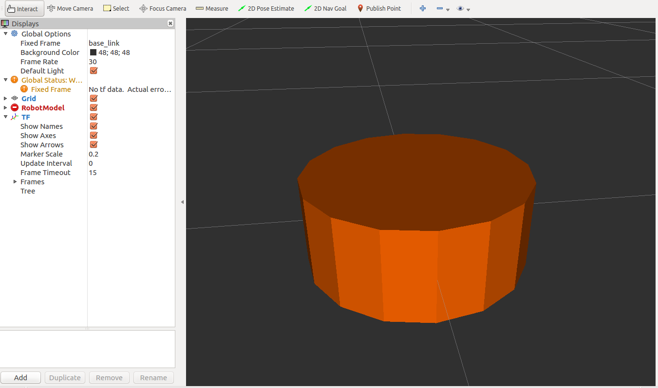
Using launch mbot_description display_mbot_base_urdf.launch starts.
The effect is shown in the figure:
If you want other rigid bodies or joints, you can add them yourself.
In particular, kinect texture description files can be used. Loading with mesh tags can achieve the effect of restoring the real object. Place kinect files in the meshes folder, modify the urdf file, and load kinect into our model. The path must be correct.
 <link name="kinect_link">
        <visual>
            <origin xyz="0 0 0" rpy="0 0 1.5708"/>
            <geometry>
                <mesh filename="package://mbot_description/meshes/kinect.dae" />
            </geometry>
        </visual>
    </link>

    <joint name="laser_joint" type="fixed">
        <origin xyz="0.15 0 0.11" rpy="0 0 0"/>
        <parent link="base_link"/>
        <child link="kinect_link"/>
    </joint>
The path of the corresponding launch file should also be modified, as shown in the figure below:

This section only creates the appearance model of the robot, and the cameras are just an empty box, which has no practical significance. It is mainly about the use of urdf files and the path of launch files. Note that there will be no problems in other places.
be accomplished!!!