summary
During the development of S32K series chips, although the SDK is officially provided and has been updated to version 4.02, and there are Processor expert one click configuration, clock, peripherals, interrupts and other components. After configuration, the driver function can be generated and called by one click dragging, and some of them need to be filled in manually. Even so, it is unclear in the development process, so the new project is only a reference transplantation without growth. Therefore, we intend to make a handwritten version of each peripheral and make records.
Clock
S32K has many clocks, including firc, SIRC, SOSC, LPO and RTC. There is no PLL in S32K1XXX series. The desired clock source and clock frequency division can be achieved by configuring the relevant enabling registers. However, it is not intuitive to read the reference manual. S32DS provides a clear structure, which is very helpful for development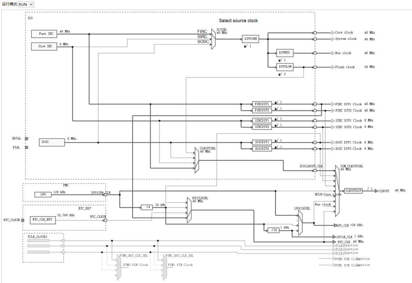
The above figure shows the clock diagram in the running state
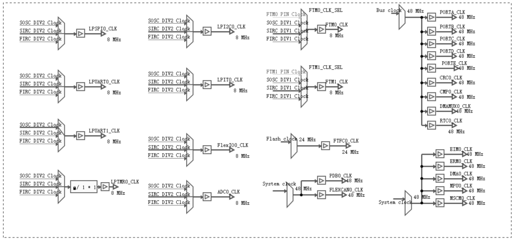
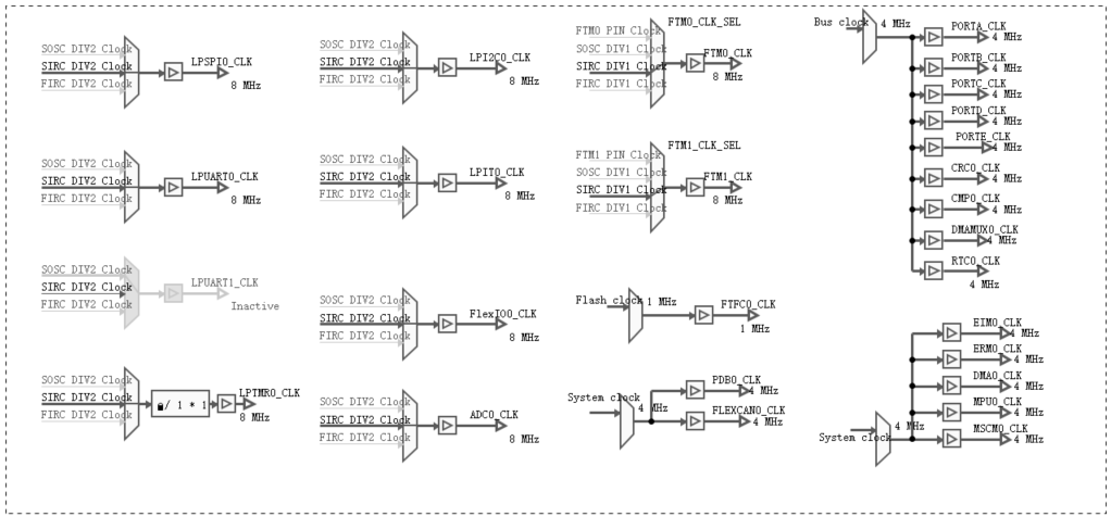
The above figure shows the clock selection of peripherals
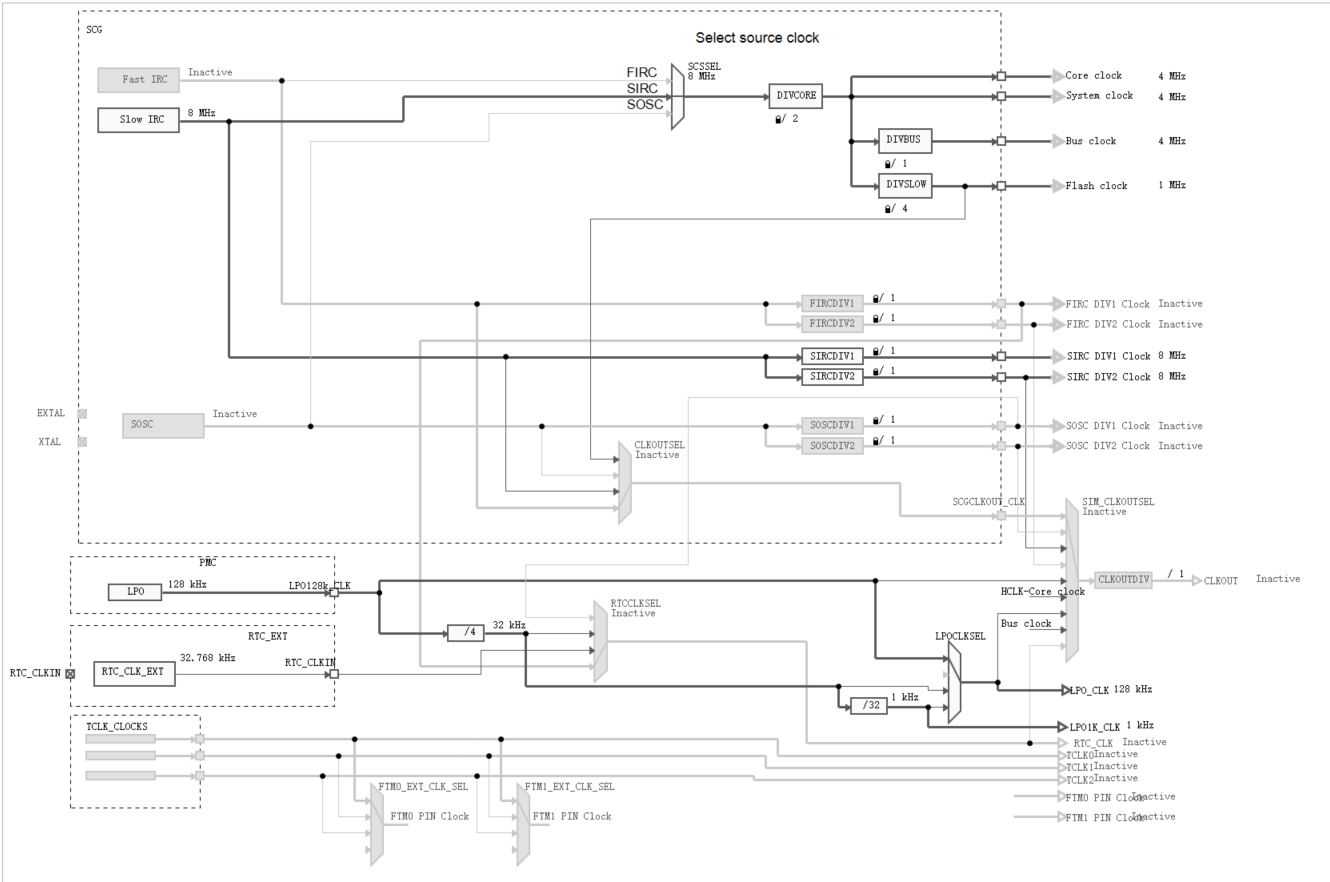
The above is the clock allocation of VCCR
Referring to the above clock diagram, you can clearly know which registers need to be configured and how the structure is composed. However, once the clock configuration is wrong, it will fail to drive the peripherals. Specifically, you can check the VLD status of the clock register in the debug mode. If there is no problem with the configuration, the position bit. When driving the serial port, I found that the transmission buffer has been in the full state. After checking for a long time, I found that the SOSCVLD bit is not set. After modifying the clock source of the serial port to SIRC, I can send data.
Clock initialization code
#include "clockdriver.h"
static void ConfigFIRC(void)
{
	SCG->FIRCCSR &= (uint32_t)(~SCG_FIRCCSR_FIRCEN_MASK);
	SCG->FIRCDIV = SCG_FIRCDIV_FIRCDIV1(1) | SCG_FIRCDIV_FIRCDIV2(1);
	SCG->FIRCCFG = SCG_FIRCCFG_RANGE(0);
	while(SCG->FIRCCSR & SCG_FIRCCSR_LK_MASK);
	SCG->FIRCCSR = SCG_FIRCCSR_FIRCEN(1);
	while((SCG->FIRCCSR & SCG_FIRCCSR_FIRCVLD_MASK) >> SCG_FIRCCSR_FIRCVLD_SHIFT != 1);
}
static void ConfigSIRC(void)
{
	SCG->SIRCCSR &= (uint32_t)(~SCG_SIRCCSR_SIRCEN_MASK);
	SCG->SIRCDIV = SCG_SIRCDIV_SIRCDIV1(1) | SCG_SIRCDIV_SIRCDIV2(1);
	SCG->SIRCCFG = SCG_SIRCCFG_RANGE(1);
	while(SCG->SIRCCSR & SCG_SIRCCSR_LK_MASK);
	SCG->SIRCCSR = SCG_SIRCCSR_SIRCEN(1);
	while((SCG->SIRCCSR & SCG_SIRCCSR_SIRCVLD_MASK) >> SCG_SIRCCSR_SIRCVLD_SHIFT != 1);
}
static void ConfigSOSC(void)
{
	SCG->SOSCDIV = SCG_SOSCDIV_SOSCDIV1(1) | SCG_SOSCDIV_SOSCDIV2(1);
	SCG->SOSCCFG = SCG_SOSCCFG_RANGE(2) | SCG_SOSCCFG_HGO(0) | SCG_SOSCCFG_EREFS(1);
	while(SCG->SOSCCSR & SCG_SOSCCSR_LK_MASK);
	SCG->SOSCCSR = SCG_SOSCCSR_SOSCEN(1);
	while((SCG->SOSCCSR & SCG_SOSCCSR_SOSCVLD_MASK) >> SCG_SOSCCSR_SOSCVLD_SHIFT != 1);
}
static void ConfigLPO(void)
{
	SIM->LPOCLKS = SIM_LPOCLKS_LPO32KCLKEN(1);
	SIM->LPOCLKS = SIM_LPOCLKS_LPO32KCLKEN(1);
	SIM->LPOCLKS = SIM_LPOCLKS_LPOCLKSEL(0);
	SIM->LPOCLKS = SIM_LPOCLKS_RTCCLKSEL(3);
 }
static void ConfigRunMode(void)
{
    SCG->RCCR = SCG_RCCR_SCS(3) | SCG_RCCR_DIVCORE(0) | SCG_RCCR_DIVSLOW(1) | SCG_RCCR_DIVBUS(0);
    while((SCG->CSR & SCG_CSR_SCS_MASK) != (uint32_t)0x03000000);
}
static void ConfigVLPRMode(void)
{
	SCG->VCCR = SCG_VCCR_SCS(2) | SCG_VCCR_DIVCORE(1) | SCG_VCCR_DIVBUS(0) | SCG_VCCR_DIVSLOW(3);
}

void ConfigClkOut(void)
{
	SCG->CLKOUTCNFG |= SCG_CLKOUTCNFG_CLKOUTSEL(1);
	SIM->CHIPCTL &= ~SIM_CHIPCTL_CLKOUTEN_MASK;
	SIM->CHIPCTL &= ~SIM_CHIPCTL_CLKOUTSEL_MASK;
	SIM->CHIPCTL |= SIM_CHIPCTL_CLKOUTSEL(2);
	SIM->CHIPCTL |= SIM_CHIPCTL_CLKOUTDIV(0);
	SIM->CHIPCTL |= SIM_CHIPCTL_CLKOUTEN(1);
}

void ClockInit(void)
{
	(void)ConfigFIRC();
	(void)ConfigSIRC();
	(void)ConfigSOSC();
	//(void)ConfigLPO();
	(void)ConfigRunMode();
	//(void)ConfigVLPRMode();
}
The serial port code only writes the transmission, enables the FIFO, and does not use the interrupt
void Uart0Init(void)
{
	PCC->PCCn[PCC_PORTC_INDEX] |= PCC_PCCn_CGC(1);
/* SET PIN PTC2 MUX AS UART0_TX, SET PIN PTC3 MUX AS UART0_RX*/
	PORTC->PCR[2] &=PORT_PCR_MUX_MASK;
	PORTC->PCR[2] |= PORT_PCR_MUX(4);//PTC2 MUX = ALT4, UART0_TX
	PORTC->PCR[3] &=PORT_PCR_MUX_MASK;
	PORTC->PCR[3] |= PORT_PCR_MUX(4);//PTC3 MUX = ALT4, UART0_RX
/* SET PIN MUX END */
/*
 * TURN OFF CLOCK BEFORE SELECT CLOCK
 * */
	PCC->PCCn[PCC_LPUART0_INDEX] &= ~PCC_PCCn_CGC_MASK;
	PCC->PCCn[PCC_LPUART0_INDEX] &= ~PCC_PCCn_PCS_MASK;
/* SELECT CLOCK SOURCE UART0 */
	PCC->PCCn[PCC_LPUART0_INDEX] |= PCC_PCCn_PCS(1);
/* SELECT CLOCK SOURCE UART0 END */
/* ENABLE CLOCK TO UART0 */
	PCC->PCCn[PCC_LPUART0_INDEX] |= PCC_PCCn_CGC(1);
/* ENABLE CLOCK TO UART0 END */
	LPUART0->CTRL &= ~LPUART_CTRL_TE_MASK;
	LPUART0->CTRL &= ~LPUART_CTRL_RE_MASK;
	LPUART0->BAUD |=  LPUART_BAUD_SBR(52);
	LPUART0->BAUD |=  LPUART_BAUD_OSR(15);
	LPUART0->CTRL |= LPUART_CTRL_TE_MASK;
	LPUART0->CTRL |= LPUART_CTRL_RE_MASK;

	LPUART0->FIFO = 0x0003C000;
	LPUART0->FIFO |= LPUART_FIFO_TXFE_MASK;
	LPUART0->FIFO |= LPUART_FIFO_RXFE_MASK;
	LPUART0->WATER = 0x00000000;
	LPUART0->WATER |= LPUART_WATER_TXWATER(3);
	LPUART0->WATER |= LPUART_WATER_RXWATER(3);


	while((LPUART0->CTRL & LPUART_CTRL_TE_MASK) != LPUART_CTRL_TE_MASK);

}

uint8_t UartSendChar(uint8_t buff)
{
	int count = 0;
	while(((LPUART0->STAT & LPUART_STAT_TDRE_MASK) != LPUART_STAT_TDRE_MASK) && count++ < 0xFFFF);
	if(count >= 0xFFFF)
		return 0;
	LPUART0->DATA = buff;
	return 1;
}

uint8_t UartSendString(uint8_t *buff,uint8_t len)
{
	uint8_t i;
	for(i = 0;i<len;i++)
	{
		if(!UartSendChar(buff[i]))
			break;
	}
	if(i < len)
		return 0;
	else
		return 1;

}
The main functions are as follows
/* ###################################################################
**     Filename    : main.c
**     Processor   : S32K1xx
**     Abstract    :
**         Main module.
**         This module contains user's application code.
**     Settings    :
**     Contents    :
**         No public methods
**
** ###################################################################*/
/*!
** @file main.c
** @version 01.00
** @brief
**         Main module.
**         This module contains user's application code.
*/
/*!
**  @addtogroup main_module main module documentation
**  @{
*/
/* MODULE main */


/* Including necessary module. Cpu.h contains other modules needed for compiling.*/
#include "Cpu.h"
#include "include.h"

uint8_t Buff2Send[3] = {0x55,0xAA,0xCC};
volatile uint32_t clocktick =  0;
volatile int exit_code = 0;

#define MAXVALUE 50000
/* User includes (#include below this line is not maintained by Processor Expert) */

/*!
  \brief The main function for the project.
  \details The startup initialization sequence is the following:
 * - startup asm routine
 * - main()
*/
int main(void)
{
  /* Write your local variable definition here */

  /*** Processor Expert internal initialization. DON'T REMOVE THIS CODE!!! ***/
  #ifdef PEX_RTOS_INIT
    PEX_RTOS_INIT();                   /* Initialization of the selected RTOS. Macro is defined by the RTOS component. */
  #endif
  /*** End of Processor Expert internal initialization.                    ***/

  /* Write your code here */
  /* For example: for(;;) { } */
    wdog_stop();
    ClockInit();
    Uart0Init();
    for(;;)
    {
    	clocktick++;
    	if(clocktick > MAXVALUE)
    	{
    		UartSendString(Buff2Send,3);
    		clocktick = 0;
    	}
    }

  /*** Don't write any code pass this line, or it will be deleted during code generation. ***/
  /*** RTOS startup code. Macro PEX_RTOS_START is defined by the RTOS component. DON'T MODIFY THIS CODE!!! ***/
  #ifdef PEX_RTOS_START
    PEX_RTOS_START();                  /* Startup of the selected RTOS. Macro is defined by the RTOS component. */
  #endif
  /*** End of RTOS startup code.  ***/
  /*** Processor Expert end of main routine. DON'T MODIFY THIS CODE!!! ***/
  for(;;) {
    if(exit_code != 0) {
      break;
    }
  }
  return exit_code;
  /*** Processor Expert end of main routine. DON'T WRITE CODE BELOW!!! ***/
} /*** End of main routine. DO NOT MODIFY THIS TEXT!!! ***/

/* END main */
/*!
** @}
*/
/*
** ###################################################################
**
**     This file was created by Processor Expert 10.1 [05.21]
**     for the NXP S32K series of microcontrollers.
**
** ###################################################################
*/
The baud rate and transmitted data can be verified by oscilloscope or logic analyzer.
The watchdog is on by default, so the first step is to disable it, which is also a pit