More exchanges, welcome tiktok, 81849645041
objective
Familiar with the working principle of SD card and SDIO. Master the reading and writing of SD card.
principle
Most single chip microcomputer systems need large capacity storage devices to store data. At present, U disk, FLASH chip, SD card and so on are commonly used. They have their own advantages. Through comprehensive comparison, the most suitable single-chip microcomputer system is the SD card. It not only has a large capacity (more than 32GB) and supports SPI/SDIO driver, but also has a variety of volume sizes to choose from (standard SD card size, TF card size, etc.), which can meet the requirements of different applications. Only a few IO ports are needed to expand an external memory of more than 32GB. The capacity ranges from tens of M to tens of G. the selection scale is very large, the replacement is also very convenient and the programming is also simple. It is the first choice for large-capacity external memory of single chip microcomputer.
There are generally two communication interfaces for the controller to read and write the SD card, one is SPI interface and the other is SDIO interface.
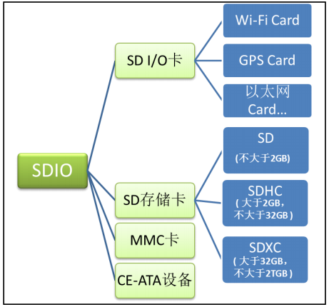
The full name of SDIO is secure digital input / output interface. Multimedia card (MMC), SD card and SD I/O card all have SDIO interface.
SD I/O card itself is not a card for storage. It refers to a peripheral using SDIO transmission protocol. For example, Wi Fi card mainly provides Wi Fi function. Some Wi Fi modules use serial port or SPI interface for communication, but Wi Fi SDIO card uses SDIO interface for communication. And the general design SD I/O card can be inserted into the SD slot.
Physical structure of SD card
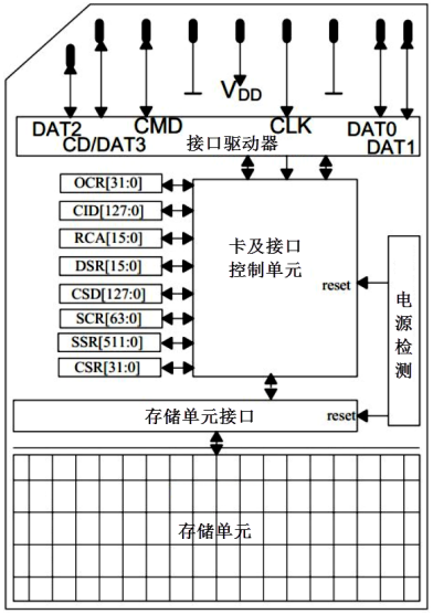
An SD card includes five parts: storage unit, storage unit interface, power detection, card, interface controller and interface driver.
The storage unit is a data storage component, and the storage unit transmits data with the card control unit through the storage unit interface; The power detection unit ensures that the SD card works at an appropriate voltage. In case of power failure or power on, it will reset the interface between the control unit and the storage unit; The SD card and interface control unit control the operation state of the SD card, which includes 8 registers; The interface driver controls the input and output of the SD card pin.
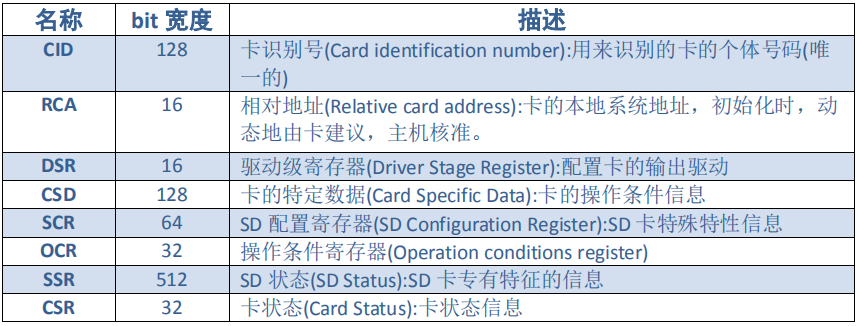
The SD card has a total of 8 registers, which are used to set or represent the SD card information. These registers can only be accessed through corresponding commands. The control operation of the SD card is not to read and write one register at a time like the operation controller GPIO related registers. It is controlled by commands. SDIO defines 64 commands, each of which has a special meaning and can realize a specific function. After the SD card receives the command, Modify the internal register of SD card according to the command requirements. In program control, you only need to send combined commands to realize the control and read-write operation of SD card.
SDIO bus
The topology of SD card bus is shown in the figure. Although the bus can be shared, it is not recommended to share the bus signal with multiple card slots. It is required that a separate SD bus should be connected to a separate SD card.
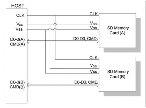
The SD card uses 9-pin interface for communication, including 3 power lines, 1 clock line, 1 command line and 4 data lines. The specific instructions are as follows:
CLK: clock line, generated by SDIO host, i.e. output by STM32 controller;
CMD: command control line through which the SDIO host sends commands to control the SD card. If the command requires the SD card to provide a response (response), the SD card also transmits the response information through the line;
D0-3: data line, transmitting read-write data; The SD card can pull d0 down to indicate busy status;
VDD, VSS1, VSS2: power and ground signals.
Whether SDIO is transmitted from the host controller to the SD card or from the SD card to the host controller, it is only valid on the rising edge of the CLK clock line. During the operation of SD card, two clocks with different frequencies will be used to synchronize data. One is the clock frequency FOD in the identification card stage, with a maximum of 400kHz. The other is the clock frequency FPP in the data transmission mode, with a maximum of 25MHz by default. If SDIO works in the high-speed mode through the configuration of relevant registers, the maximum frequency of the data transmission mode is 50MHz.
SD bus communication is based on command and data transmission. Communication is terminated by a start bit ("0") and a stop bit ("1"). SD communication generally means that the host sends a command and the slave device responds after receiving the command. If necessary, data transmission will participate.
SD data is transmitted in block (Black). The length of SDHC card data block is generally 512 bytes. Data can be from host to card or from card to host. The data block needs CRC bit to ensure successful data transmission. CRC bit is generated by SD card system hardware. STM32 controller can control the use of single wire or 4-wire transmission. This development board is designed to use 4-wire transmission.
Command format
The SD command is issued by the host. Take the broadcast command and addressing command as an example. The broadcast command is sent to all slave devices connected to the SD host bus. The addressing command is to specify an address device for command transmission.
The SD command format is fixed at 48bit and is continuously transmitted through CMD line (data line does not participate).
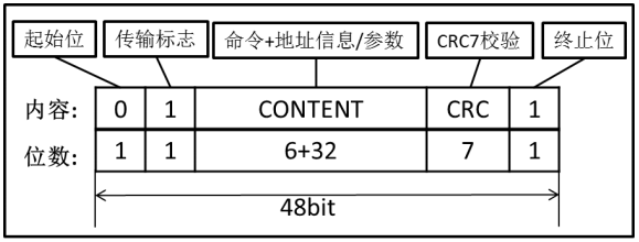
The SD command consists of the following:
Start bit and end bit: the body of the command is contained between the start bit and end bit. Both of them contain only one data bit. The start bit is 0 and the end bit is 1.
Transmission flag: used to distinguish the transmission direction. When this bit is 1, it indicates the command, the direction is the transmission from the host to the SD card, when this bit is 0, it indicates the response, and the direction is the transmission from the SD card to the host.
The main content of the command includes three parts: command, address information / parameters and CRC verification.
Command number: it occupies 6 bits, so there are 64 commands in total (Code: CMD0~CMD63). Each command has a specific purpose. Some commands are not applicable to SD card operation, but only for MMC card or SD I/O card.
Address / parameters: each command has 32bit address information / parameters for additional contents of the command. For example, the broadcast command has no address information, which is used to specify parameters, while the addressing command is used to specify the address of the target SD card.
CRC7 verification: the verification bit with the length of 7 bits is used to verify the correctness of the command transmission content. If the state of individual bits of the transmission data is changed due to external interference, the calibration will fail, which also means that the command transmission fails, and the SD card will not execute the command.
Command type
There are four types of SD commands:
Unresponsive broadcast command (bc), which is sent to all cards and does not return task response;
With response broadcast command (bcr), send to all cards and receive responses from all cards at the same time;
The addressing command (ac) is sent to the selected card, and the DAT line has no data transmission;
The addressing data transmission command (adtc) is sent to the selected card, and the DAT line has data transmission.
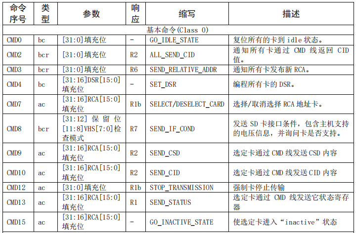
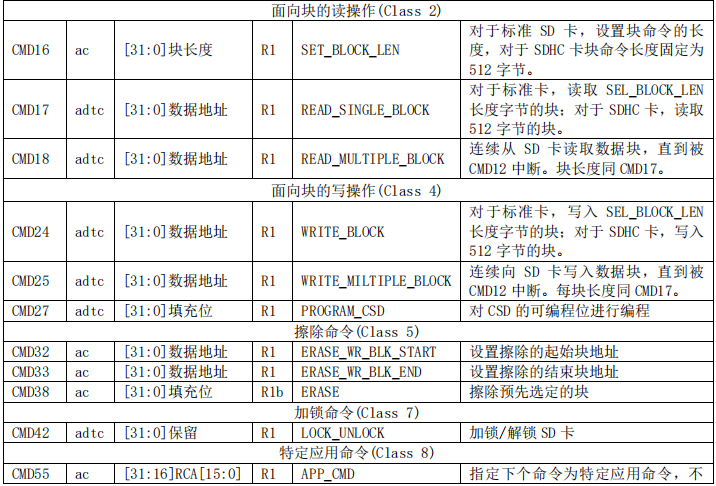
Command description
The commands of SD card system are divided into several classes, and each class supports a "card function setting".
response
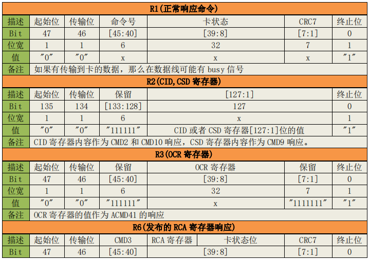
The response is sent from the SD card to the host. Some commands require the SD card to respond. These responses are mostly used to feed back the status of the SD card. SDIO has a total of 7 response types (Codes: R1~R7), among which the SD card has no R4 and R5 response types. A specific command corresponds to a specific response type. For example, when the host sends the CMD3 command, you can get the response R6. Like the command, the response of SD card is transmitted continuously through CMD line. According to the size of the response content, it can be divided into short response and long response. The short response is 48bit long, and only R2 type is long response, which is 136bit long.
SD card initialization process
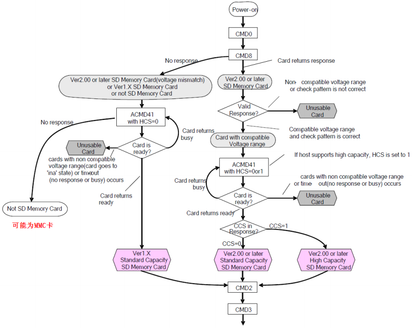
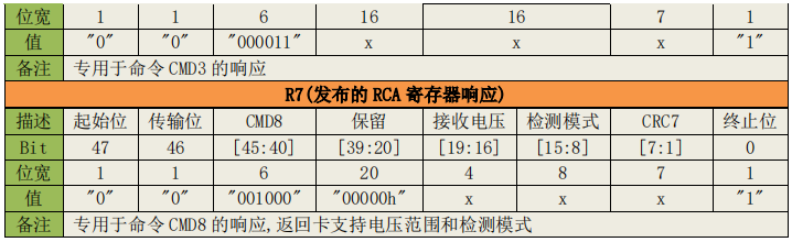
From the figure, we can see that no matter what kind of card (here we divide the card into four categories: SD2.0 high capacity card (SDHC, maximum 32G), SD2 0 standard capacity card (SDSC, 2G maximum), sd1 X card and MMC card). First, we need to power on the card (SDIO_POWER[1:0]=11 needs to be set). After power on, send CMD0, soft reset the card, and then send CMD8 command to distinguish SD card 2.0. Only cards 2.0 and later can support CMD8 command, MMC card and v1.0 X card does not support this command. The format of CMD8 is shown in table.
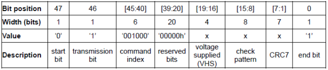
When sending CMD8, we can set the VHS bit through its parameters to tell the SD card and the power supply of the host. The definition of VHS bit is shown in the table below:
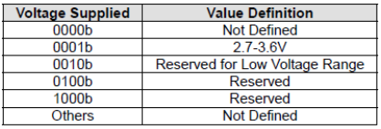
Here we use the parameter 0X1AA, that is, tell the SD card that the host power supply is between 2.7~3.6V. If the SD card supports CMD8 and supports the voltage range, the parameter part will be returned to the host through the response (R7) of CMD8. If CMD8 is not supported or the voltage range is not supported, there will be no response.
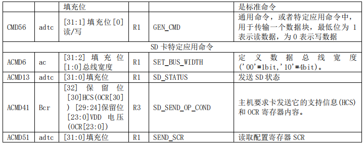
After sending CMD8, send ACMD41 (note that CMD55 should be sent before sending ACMD41) to further confirm the operating voltage range of the card, and tell the SD card whether the host supports high-capacity card (SDHC) through HCS bit. The command format of ACMD41 is shown in the table below:
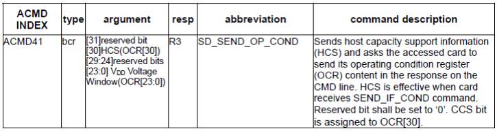
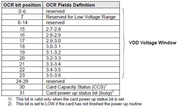
The response (R3) obtained by ACMD41 includes the contents of the OCR register of the SD card. The contents of the OCR register are defined in the table below:
For the card that supports the CMD8 instruction, the host tells the SD card host to support the SDHC card by setting the HCS bit to 1 through the parameter of ACMD41. If it is set to 0, it means that the host does not support the SDHC card. If the HCS received by the SDHC card is 0, it will never return to the card ready state. For cards that do not support CMD8, set the HCS bit to 0.
After receiving ACMD41, the SD card returns the contents of OCR register. If it is a 2.0 card, the host can judge whether it is SDHC or SDSC by judging the CCS bit of OCR; If it is 1 X card, this bit is ignored. The last bit of OCR register is used to tell the host whether the SD card is powered on. If the power on is completed, this bit will be set to 1.
For MMC card, ACMD41 is not supported and CMD55 is not responded to. For MMC card, we only need to check the OCR register of MMC card after sending CMD0 and CMD1 (the same function as ACMD41) to realize the initialization of MMC card.
So far, we have realized the type differentiation of SD card. In the flow chart, we finally sent CMD2 and CMD3 commands to obtain card CID register data and card relative address (RCA).
CMD2 is used to obtain the data of CID register. The data bits of CID register are defined in the table below:
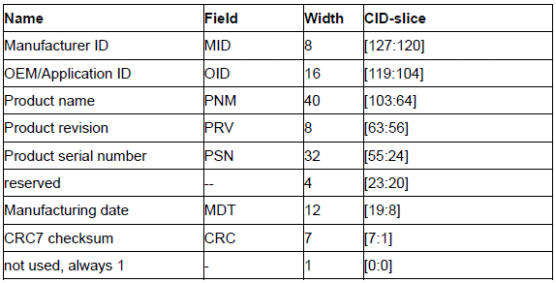
After receiving CMD2, the SD card will return R2 long response (136 bits), including 128 bits of valid data (CID register content), which is stored in SDIO_RESP1~4 and other four registers. By reading these four registers, the CID information of SD card can be obtained.
CMD3 is used to set the relative address of the card (RCA, which must be non-0). For SD card (non MMC card), after receiving CMD3, a new RCA will be returned to the host to facilitate host addressing. The existence of RCA allows one SDIO interface to hang multiple SD cards. RCA can distinguish which card the host wants to operate. For MMC card, instead of the SD card automatically returning RCA, the host actively sets the RCA of MMC card, that is, the RCA setting is realized through CMD3 with parameters (the high 16 bits are used for RCA setting). Similarly, the MMC card also supports one SDIO interface to hang multiple MMC cards. Unlike the SD card, all RCAs are actively set by the host, while the RCA of the SD card is sent to the host by the SD card.
After obtaining the card RCA, we can send CMD9 (with RCA parameters) to obtain the contents of the SD card CSD register. From the CSD register, we can obtain very important information such as the capacity and sector size of the SD card.
So far, our SD card initialization is basically over. Finally, select the SD card we want to operate through the CMD7 command to start the read-write operation of the SD card.
prepare
MDK5 development environment.
STM32F4xx HAL library.
STM32F407 development board.
STM32F4xx reference manual.
STM32F4xx data book.
Circuit schematic diagram of STM32F407 development board.
step
- New bsp_sd.h and bsp_sd.c. In BSP_ sd. Define the required macros and functions in H.
#ifndef __BSP_SD_H
#define __BSP_SD_H

#include "stm32f4xx.h"

// Supported SD card definitions
#define SDIO_STD_CAPACITY_SD_CARD_V1_1             ((uint32_t)0x00000000)
#define SDIO_STD_CAPACITY_SD_CARD_V2_0             ((uint32_t)0x00000001)
#define SDIO_HIGH_CAPACITY_SD_CARD                 ((uint32_t)0x00000002)
#define SDIO_MULTIMEDIA_CARD                       ((uint32_t)0x00000003)
#define SDIO_SECURE_DIGITAL_IO_CARD                ((uint32_t)0x00000004)
#define SDIO_HIGH_SPEED_MULTIMEDIA_CARD            ((uint32_t)0x00000005)
#define SDIO_SECURE_DIGITAL_IO_COMBO_CARD          ((uint32_t)0x00000006)
#define SDIO_HIGH_CAPACITY_MMC_CARD                ((uint32_t)0x00000007)

// GPIOC D0-D3  SCK
#define Pin_SDIO_D0_D3	 GPIO_PIN_8 | GPIO_PIN_9 | GPIO_PIN_10 | GPIO_PIN_11
#define Pin_SDIO_SCK 		 GPIO_PIN_12
// GPIOD CMD
#define Pin_SDIO_CMD		 GPIO_PIN_2

uint8_t SDCard_Init(void); // Initialization function
uint8_t SD_GetCardInfo(HAL_SD_CardInfoTypeDef *cardinfo); // Get sd card information
void    SDCard_Show_Info(HAL_SD_CardInfoTypeDef *cardinfo);	// Print sd card information
uint8_t SD_ReadDisk(uint8_t* buf, uint32_t sector, uint32_t cnt);	// Read data
uint8_t SD_WriteDisk(uint8_t *buf, uint32_t sector, uint32_t cnt); // Write data
#endif
- In BSP_ sd. Implement SD initialization and read-write operation functions in C.
#include "bsp_sd.h"

SD_HandleTypeDef SD_Handle;

/**
*  Function name: SD_Init
*  Description: SD card initialization
*  Input:
*  Output: return value: 0, initialization is correct;
*/
uint8_t SDCard_Init(void)
{
	uint8_t sta;

	__HAL_RCC_SDIO_CLK_ENABLE();
	__SDIO_CLK_ENABLE();

	SD_Handle.Instance = SDIO;
	SD_Handle.Init.BusWide = SDIO_BUS_WIDE_1B; // 1-bit data line
	SD_Handle.Init.ClockBypass = SDIO_CLOCK_BYPASS_DISABLE; // bypass mode is not used
	SD_Handle.Init.ClockDiv = SDIO_TRANSFER_DIR_TO_SDIO; // SD transmission clock frequency
	SD_Handle.Init.ClockEdge = SDIO_CLOCK_EDGE_RISING; // Rising edge
	SD_Handle.Init.ClockPowerSave = SDIO_CLOCK_POWER_SAVE_DISABLE; // Do not turn off the clock power when idle
	SD_Handle.Init.HardwareFlowControl = SDIO_HARDWARE_FLOW_CONTROL_DISABLE; // Turn off hardware flow control

	sta = HAL_SD_Init(&SD_Handle);

	HAL_SD_ConfigWideBusOperation(&SD_Handle,SDIO_BUS_WIDE_4B); // Enable 4-bit wide bus mode

	return sta;
}

/**
*  Function name: HAL_SD_MspInit
*  Description: SD card initialization callback function is used for pin initialization
*  Input: hsd handle
*  Output: return value: 0, initialization is correct;
*/
void HAL_SD_MspInit(SD_HandleTypeDef *hsd)
{
	GPIO_InitTypeDef  GPIO_InitStruct;

	__HAL_RCC_GPIOC_CLK_ENABLE();
	__HAL_RCC_GPIOD_CLK_ENABLE();

	GPIO_InitStruct.Mode = GPIO_MODE_AF_PP;
	GPIO_InitStruct.Pull = GPIO_PULLUP;
	GPIO_InitStruct.Speed = GPIO_SPEED_FAST;
	GPIO_InitStruct.Alternate = GPIO_AF12_SDIO;

	GPIO_InitStruct.Pin = Pin_SDIO_D0_D3 | Pin_SDIO_SCK; // D0~D3 SCK pin
	HAL_GPIO_Init(GPIOC, &GPIO_InitStruct);
	GPIO_InitStruct.Pin = Pin_SDIO_CMD;	// CMD pin
	HAL_GPIO_Init(GPIOD, &GPIO_InitStruct);
}

/**
*  Function name: SD_GetCardInfo
*  Description: get card information
*  Input: HAL_SD_CardInfoTypeDef
*  Output: status value
*/
uint8_t SD_GetCardInfo(HAL_SD_CardInfoTypeDef *cardinfo)
{
	uint8_t sta;
	sta = HAL_SD_GetCardInfo(&SD_Handle, cardinfo); // Get card information
	return sta;
}

// Print SD card information
void SDCard_Show_Info(HAL_SD_CardInfoTypeDef *cardinfo)
{
	switch(cardinfo->CardType) //Card type
	{
		case SDIO_STD_CAPACITY_SD_CARD_V1_1:
			printf("Card Type:SDSC V1.1\r\n");
		break;
		case SDIO_STD_CAPACITY_SD_CARD_V2_0:
			printf("Card Type:SDSC V2.0\r\n");
		break;
		case SDIO_HIGH_CAPACITY_SD_CARD:
			printf("Card Type:SDHC V2.0\r\n");
		break;
		case SDIO_MULTIMEDIA_CARD:
			printf("Card Type:MMC Card\r\n");
		break;
	}
	printf("Card CardVersion:%d\r\n", cardinfo->CardVersion); // Version number
	printf("Card RelCardAdd:%d\r\n", cardinfo->RelCardAdd); // Card relative address
	printf("Card BlockNbr:%d\r\n", cardinfo->BlockNbr); // Displays the number of blocks
	printf("Card BlockSize:%d\r\n", cardinfo->BlockSize); // Display block size
}

/**
*  Function name: SD_ReadDisk
*  Description: read SD card
*  Input: buf: read data buffer sector: sector address cnt: number of sectors
*  Output: return value: error status; 0, normal;
*/
uint8_t SD_ReadDisk(uint8_t* buf, uint32_t sector, uint32_t cnt)
{
	uint8_t sta;

	sta = HAL_SD_ReadBlocks(&SD_Handle, buf, sector, cnt, 1000);

	return sta;
}

/**
*  Function name: SD_WriteDisk
*  Description: write SD card
*  Input: buf: write data buffer sector: sector address cnt: number of sectors
*  Output: return value: error status; 0, normal;
*/
uint8_t SD_WriteDisk(uint8_t *buf, uint32_t sector, uint32_t cnt)
{
	uint8_t sta;

	sta = HAL_SD_WriteBlocks(&SD_Handle, buf, sector, cnt, 1000);

	return sta;
}
- main. Read and write the specified sector data in C
#include "bsp_clock.h"
#include "bsp_uart.h"
#include "bsp_key.h"
#include "bsp_sd.h"
#include "bsp_led.h"

HAL_SD_CardInfoTypeDef pCardInfo;

int main(void)
{
	uint8_t sta,size;
	uint8_t txbuf[] = {"SD Card ReadWrite Test"};
	size = sizeof(txbuf);
	uint8_t rxbuf[size];

	CLOCLK_Init(); // Initialize system clock
	UART_Init(); // Serial port initialization
	KEY_Init(); // Key initialization
	LED_Init(); // LED initialization

	sta = SDCard_Init();// sd initialization return status

	if(sta == HAL_OK) // Initialization succeeded
	{
		LED1_ON;
		SD_GetCardInfo(&pCardInfo); // Get sd card device information
		HAL_Delay(50);
		SDCard_Show_Info(&pCardInfo); // Display sd card device information
	}

	while(1)
	{
		uint8_t key = KEY_Scan(0);

		if( key == 1) // KEY0 press
		 {
			 SD_WriteDisk(txbuf, 0, 1); // Send test data
			 printf("Write buf: %s \n", txbuf);
		 }

		 if( key == 2) // KEY1 press
		 {
			 SD_ReadDisk(rxbuf, 0, 1); // read
			 printf("Read  buf: %s \n", rxbuf);
		 }

		 HAL_Delay(50);
	}
}
phenomenon
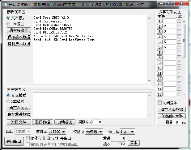
Open the serial assistant and download the compiled program to the development board. Print the SD card information first.
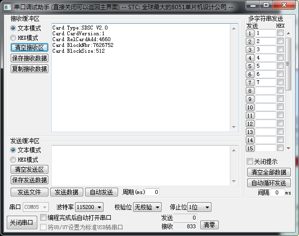
Press KEY0 to write data. Press key1 to read data from the address.