Introduction
When using stm32 or other single-chip computers, serial communication is often used, so how to effectively receive data? If this data is indefinite, how can it be received efficiently?
Classmate A: when the data comes, it will enter into the serial port and interrupt. Just read the data in the interrupt!
Interrupt is to interrupt the normal operation of the program. How can we ensure high efficiency? Often interrupt the main program. Do you want to run the main program?
Classmate B: the serial port can be configured to receive data by DMA. After receiving, you can read it!
This student is right. We can use DMA to receive data, but DMA needs a fixed length to generate a receive interrupt. How can we receive indefinite data?
DMA introduction
In fact, it is necessary to think about the above problems. Only by thinking constantly can we make progress.
What is DMA?
DMA: full name Direct Memory Access, i.e. Direct Memory Access
DMA transfers copy data from one address space to another. The CPU only needs to initialize DMA, and the transfer itself is realized and completed by DMA controller. A typical example is moving a block of external memory to a faster memory area inside the chip. This kind of operation does not involve the processor in processing. The CPU can do other things. When DMA transmission is completed, an interrupt will be generated to tell the CPU that I have finished, and then the CPU can process the data when it knows it. This improves the utilization rate of the CPU. Because the CPU is a big brain, it mainly deals with data operation, rather than data handling. DMA transmission is very important for efficient embedded system algorithm and network.
DMA resources in STM32
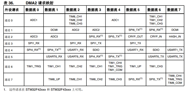
STM32F1 Series MCU has two DMA controllers (DMA2 only exists in large capacity products), DMA1 has seven channels, DMA2 has five channels, each channel is specially used to manage access requests from one or more peripherals to memory. There is also an arbiter to coordinate the priority of each DMA request.


The MCU of STM32F4/F7/H7 series has two DMA controllers with a total of 16 data streams (8 for each DMA controller). Each DMA controller is used to manage the memory access requests of one or more peripherals. Each data stream can have up to eight channels (or requests) in total. Each channel has an arbiter that handles the priority between DMA requests.
DMA receive data
When DMA receives data, the serial port receives DMA when it initializes. It is always waiting for the data to arrive. There is no need to do anything in the software, as long as the configuration is set when initializing the configuration. When receiving the data, tell the CPU to process it.
Judge the completion of data receiving
So the question is, how do you know if the data is received?
In fact, there are many ways:
- For fixed length data, you only need to judge the number of data received to know whether the reception is complete. This is very simple and will not be discussed for the moment.
- In fact, there are several methods for indefinite data. I won't introduce them to you. Students who are interested in doing complex work can see how others do it on the Internet. The following method is the simplest, making full use of stm32's serial port resources, and the efficiency is also very high.
DMA + serial port idle interrupt
These two resources match seamlessly. No matter what kind of indefinite data you receive, no matter how much data you have, I'll take one of them. It's like Cantonese eating "mangosteen" and one of them (I'm afraid it's windy recently).
When learning stm32, many people may not know what idle is. First, look at the status register of stm32 serial port:
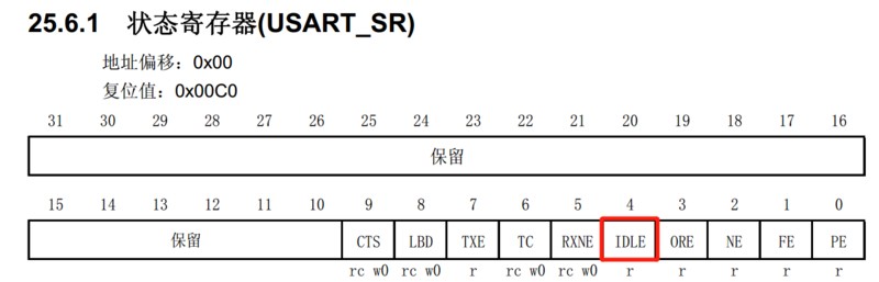

When we detect the triggering of the idle interrupt of the serial bus, we know that this wave of data transmission is completed, and then we can get these data and process them. This method is the simplest. We don't need to do much processing at all. We just need to configure the serial port to wait for the arrival of data. dma is also in the working state. When a data comes, it will automatically move a data.
Processing after receiving data
After receiving the data from the serial port, we need to process it. What are the processing steps?
- There are two reasons for temporarily shutting down the receiving DMA channel of serial port: 1. To prevent the data from being received and causing interference, because the data at this time has not been processed. 2.DMA needs to be reconfigured.
- Clear DMA flag.
- Get the received data bytes from DMA register (optional).
- Reset the number of data bytes to be received by DMA next time. Note that the number of data transfers ranges from 0 to 65535. This register can only be written when the channel is not working (EN = 0 for DMA ﹣ ccrx). When the channel is turned on, the register becomes read-only, indicating the number of bytes remaining to be transmitted. The register contents are decremented after each DMA transfer. After the data transmission, the contents of the register will either change to 0, or when the channel is configured to auto reload mode, the contents of the register will be automatically reloaded to the value of the previous configuration. When the content of the register is 0, no data transmission will occur whether the channel is on or not.
- Give the semaphore, send and receive the new data flag for the foreground program to query.
- Turn on the DMA channel and wait for the next data reception. Note that when writing the DMA related register configuration, such as resetting the DMA received data length, it must be done under the condition of turning off DMA, otherwise the operation is invalid.
Matters needing attention
When there is no data receiving at the serial port, the interrupt of STM32 IDLE will not be generated all the time. The generated condition is as follows: when the IDLE flag bit is cleared, the first data must be received before triggering. When the received data is disconnected and no data is received, the IDLE interrupt will be generated. If the data frame transmission rate of interrupt is very fast, MCU can't process the data received this time. If the interrupt sends data again, it can't be turned on here, otherwise the data will be overwritten. There are two solutions:
- Before reopening the receiving DMA channel, copy the data in Rx buf buffer to another array, then turn on DMA, and process the copied data immediately.
- Set up double buffer, reconfigure the buffer address of DMA ﹣ memorybaseaddr, then the next received data will be saved in the new buffer, which will not be overwritten.
Program realization
Experimental results:
When sending data to MCU from outside, assuming that the data length of this frame is 1000 bytes, when MCU receives a byte, there will be no serial port interruption, but DMA silently carries the data to the buffer specified by you behind. When the whole frame data is sent, the serial port will generate an interrupt. At this time, the DMA ﹐ getcurrdatacounter() function can be used to calculate the data acceptance length of this time, so as to carry out data processing.
Configuration of serial port
It's very simple. It's basically the same as when using the serial port, except that we usually open the receive buffer for non null interrupts, and now we open the idle interrupts - USART ﹣ itconfig (debug ﹣ usartx, USART ﹣ it ﹣ idle, enable);.
/**
  * @brief  USART GPIO Configuration, working parameter configuration
  * @param  nothing
  * @retval nothing
  */
void USART_Config(void)
{
    GPIO_InitTypeDef GPIO_InitStructure;
    USART_InitTypeDef USART_InitStructure;

    // Turn on the clock of serial port GPIO
    DEBUG_USART_GPIO_APBxClkCmd(DEBUG_USART_GPIO_CLK, ENABLE);

    // Turn on the clock of serial peripheral
    DEBUG_USART_APBxClkCmd(DEBUG_USART_CLK, ENABLE);

    // Configure GPIO of USART Tx as push pull multiplexing mode
    GPIO_InitStructure.GPIO_Pin = DEBUG_USART_TX_GPIO_PIN;
    GPIO_InitStructure.GPIO_Mode = GPIO_Mode_AF_PP;
    GPIO_InitStructure.GPIO_Speed = GPIO_Speed_50MHz;
    GPIO_Init(DEBUG_USART_TX_GPIO_PORT, &GPIO_InitStructure);

  // Configure GPIO of USART Rx as floating input mode
    GPIO_InitStructure.GPIO_Pin = DEBUG_USART_RX_GPIO_PIN;
    GPIO_InitStructure.GPIO_Mode = GPIO_Mode_IN_FLOATING;
    GPIO_Init(DEBUG_USART_RX_GPIO_PORT, &GPIO_InitStructure);

    // Configure the working parameters of the serial port
    // Configure baud rate
    USART_InitStructure.USART_BaudRate = DEBUG_USART_BAUDRATE;
    // Configure pin data word length
    USART_InitStructure.USART_WordLength = USART_WordLength_8b;
    // Configure stop bits
    USART_InitStructure.USART_StopBits = USART_StopBits_1;
    // Configure check bit
    USART_InitStructure.USART_Parity = USART_Parity_No ;
    // Configure hardware flow control
    USART_InitStructure.USART_HardwareFlowControl =
    USART_HardwareFlowControl_None;
    // Configure working mode, send and receive together
    USART_InitStructure.USART_Mode = USART_Mode_Rx | USART_Mode_Tx;
    // Complete initialization configuration of serial port
    USART_Init(DEBUG_USARTx, &USART_InitStructure);
    // Serial port interrupt priority configuration
    NVIC_Configuration();

#if USE_USART_DMA_RX
    // Open serial idle IDL interrupt
    USART_ITConfig(DEBUG_USARTx, USART_IT_IDLE, ENABLE);
  // Enable serial DMA reception
    USART_DMACmd(DEBUG_USARTx, USART_DMAReq_Rx, ENABLE);
    /* Enable serial DMA */
    USARTx_DMA_Rx_Config();
#else
    // Enable serial port receive interrupt
    USART_ITConfig(DEBUG_USARTx, USART_IT_RXNE, ENABLE);
#endif

#if USE_USART_DMA_TX
    // Enable serial DMA transmission
//    USART_DMACmd(DEBUG_USARTx, USART_DMAReq_Tx, ENABLE);
    USARTx_DMA_Tx_Config();
#endif

    // Enable serial port
    USART_Cmd(DEBUG_USARTx, ENABLE);
}
Serial DMA configuration
After DMA configuration is completed, DMA can be turned on directly, and it can be moved directly when there is data.
#if USE_USART_DMA_RX

static void USARTx_DMA_Rx_Config(void)
{
    DMA_InitTypeDef DMA_InitStructure;

    // Turn on DMA clock
    RCC_AHBPeriphClockCmd(RCC_AHBPeriph_DMA1, ENABLE);
    // Set DMA source address: serial port data register address*/
    DMA_InitStructure.DMA_PeripheralBaseAddr = (uint32_t)USART_DR_ADDRESS;
    // Memory address (pointer to variable to transfer)
    DMA_InitStructure.DMA_MemoryBaseAddr = (uint32_t)Usart_Rx_Buf;
    // Direction: from memory to peripherals
    DMA_InitStructure.DMA_DIR = DMA_DIR_PeripheralSRC;
    // Transmission size
    DMA_InitStructure.DMA_BufferSize = USART_RX_BUFF_SIZE;
    // Peripheral address does not increase
    DMA_InitStructure.DMA_PeripheralInc = DMA_PeripheralInc_Disable;
    // Memory address auto increment
    DMA_InitStructure.DMA_MemoryInc = DMA_MemoryInc_Enable;
    // Peripheral data unit
    DMA_InitStructure.DMA_PeripheralDataSize =
    DMA_PeripheralDataSize_Byte;
    // Memory data unit
    DMA_InitStructure.DMA_MemoryDataSize = DMA_MemoryDataSize_Byte;
    // DMA mode, once or cycle mode
    //DMA_InitStructure.DMA_Mode = DMA_Mode_Normal ;
    DMA_InitStructure.DMA_Mode = DMA_Mode_Circular;
    // Priority: medium
    DMA_InitStructure.DMA_Priority = DMA_Priority_VeryHigh;
    // Disable memory to memory transfer
    DMA_InitStructure.DMA_M2M = DMA_M2M_Disable;
    // Configure DMA channel
    DMA_Init(USART_RX_DMA_CHANNEL, &DMA_InitStructure);
    // Clear all DMA flags
    DMA_ClearFlag(DMA1_FLAG_TC5);
    DMA_ITConfig(USART_RX_DMA_CHANNEL, DMA_IT_TE, ENABLE);
    // Enabling DMA
    DMA_Cmd (USART_RX_DMA_CHANNEL,ENABLE);
}
#endif
Data processing after receiving
Because after receiving data, there will be an idle interrupt, that is, idle interrupt. Then we can know that we have received data in the interrupt service function, and we can process the data. But the context of the interrupt service function is interrupt. So, try to fast forward and fast out. Generally, set some flags in the interrupt for the foreground to query. In the interrupt, first judge whether the type of interrupt we generate is idle interrupt. If so, proceed to the next step, otherwise, we will ignore it.
/**
  ******************************************************************
  * @brief   Serial port interrupt service function
  * @author  jiejie
  * @version V1.0
  * @date    2018-xx-xx
  ******************************************************************
  */
void DEBUG_USART_IRQHandler(void)
{
#if USE_USART_DMA_RX
    /* Using serial DMA */
    if(USART_GetITStatus(DEBUG_USARTx,USART_IT_IDLE)!=RESET)
    {
        /* receive data */
        Receive_DataPack();
        // Clear idle interrupt flag bit
        USART_ReceiveData( DEBUG_USARTx );
    }
#else
  /* Interruption of reception */
    if(USART_GetITStatus(DEBUG_USARTx,USART_IT_RXNE)!=RESET)
    {
    Receive_DataPack();
    }
#endif
}
Receive_DataPack()
This is the real receive data processing function. Why should I package this function separately? Because this function is actually very important, because my code is compatible with normal serial port reception and idle interrupt, and the processing of different reception types is different, so it is better to package it directly. In the source code, we can choose the way of reception through macro definition! Considering the compatible operating system, maybe I will use dma + idle interrupt in the system, so the semaphore for the foreground query may be different, and it may need to be modified, so I will encapsulate it. But it doesn't matter. It's the same.
/************************************************************
  * @brief   Uart_DMA_Rx_Data
  * @param   NULL
  * @return  NULL
  * @author  jiejie
  * @github  https://github.com/jiejieTop
  * @date    2018-xx-xx
  * @version v1.0
  * @note    Functions called when receiving with serial DMA
  ***********************************************************/
#if USE_USART_DMA_RX
void Receive_DataPack(void)
{
    /* Received data length */
    uint32_t buff_length;

    /* Turn off DMA to prevent interference */
    DMA_Cmd(USART_RX_DMA_CHANNEL, DISABLE);  /* dma is temporarily shut down, data has not been processed */

    /* Clear DMA flag */
    DMA_ClearFlag( DMA1_FLAG_TC5 );

    /* Get the received data length in bytes*/
    buff_length = USART_RX_BUFF_SIZE - DMA_GetCurrDataCounter(USART_RX_DMA_CHANNEL);

    /* Get data length */
    Usart_Rx_Sta = buff_length;

    PRINT_DEBUG("buff_length = %d\n ",buff_length);

    /* Reassign the count value, which must be greater than or equal to the maximum possible number of data frames received */
    USART_RX_DMA_CHANNEL->CNDTR = USART_RX_BUFF_SIZE;

    /* You should open it after processing the data, such as in datapack process().*/
    DMA_Cmd(USART_RX_DMA_CHANNEL, ENABLE);

    /* (OS)Give a signal, send and receive a new data flag for the foreground program to query */

    /* Mark receiving completed, and handle in datapack.*/
    Usart_Rx_Sta |= 0xC000;

    /*
    DMA Open, wait for data. Note that if the rate of interrupt sending data frame is very fast, MCU can not process the received data.
    If the interrupt sends data again, it cannot be enabled here, otherwise the data will be overwritten. There are two solutions:

    1. Before reopening the receiving DMA channel, copy the data in Rx buf buffer to another array.
    Then turn on DMA and process the copied data immediately.

    2. Set up double buffer, reconfigure the buffer address of DMA ﹣ memorybaseaddr, then the next received data will
    Save to a new buffer without being overwritten.
    */
}
Using dma in f1 is very simple. I also encountered some problems when using dma in f4. At last, I read the manual to solve them. I plan to write the debugging process in the next article. There is nothing that debugging can't solve. If there is, it will be twice. Today's typhoon weather, even my roommate's WiFi update article ~ China Telecom is still strong, the typhoon weather signal is not false, my mobile card is motionless -.
Like to pay attention to me!

Relevant codes can be obtained by reply in the public account background.
Welcome to the public account of "IoT development"