Introduction: for the serial port to receive some variable length data, we must face a problem: how to judge whether a frame of data reception is completed? RXNE non null interrupt is usually used in combination with simple data protocol. Frame header and frame tail are added to the data. Judge whether the frame tail is received in the program to determine whether the data is received. Therefore, it is necessary to trigger interrupt for each byte to judge, which consumes system resources, especially in some occasions with high real-time requirements, The idle interrupt of serial port can greatly simplify the judgment of data receiving process. This paper introduces how to use DMA+IDLE serial port idle interrupt to accept variable length data based on stm32cubemx.
IDLE interrupt generation mechanism of STM32
IDLE interrupt is detected after monitoring the data reception (i.e. RXNE bit of serial port is set). When there is no new data reception on the bus within a cycle corresponding to a byte, the IDLE bit that controls to trigger the IDLE interrupt is set to 1 by the hardware, and an IDLE interrupt will be triggered. In the interrupt processing function, we can parse the received indefinite length data.
Use tools
Software: stm32cubemx, Keil uvision5, serial port transceiver software (vofa +),
Hardware: stm32f103rct6, St link Downloader, data cable
Stm32subemx initialization configuration
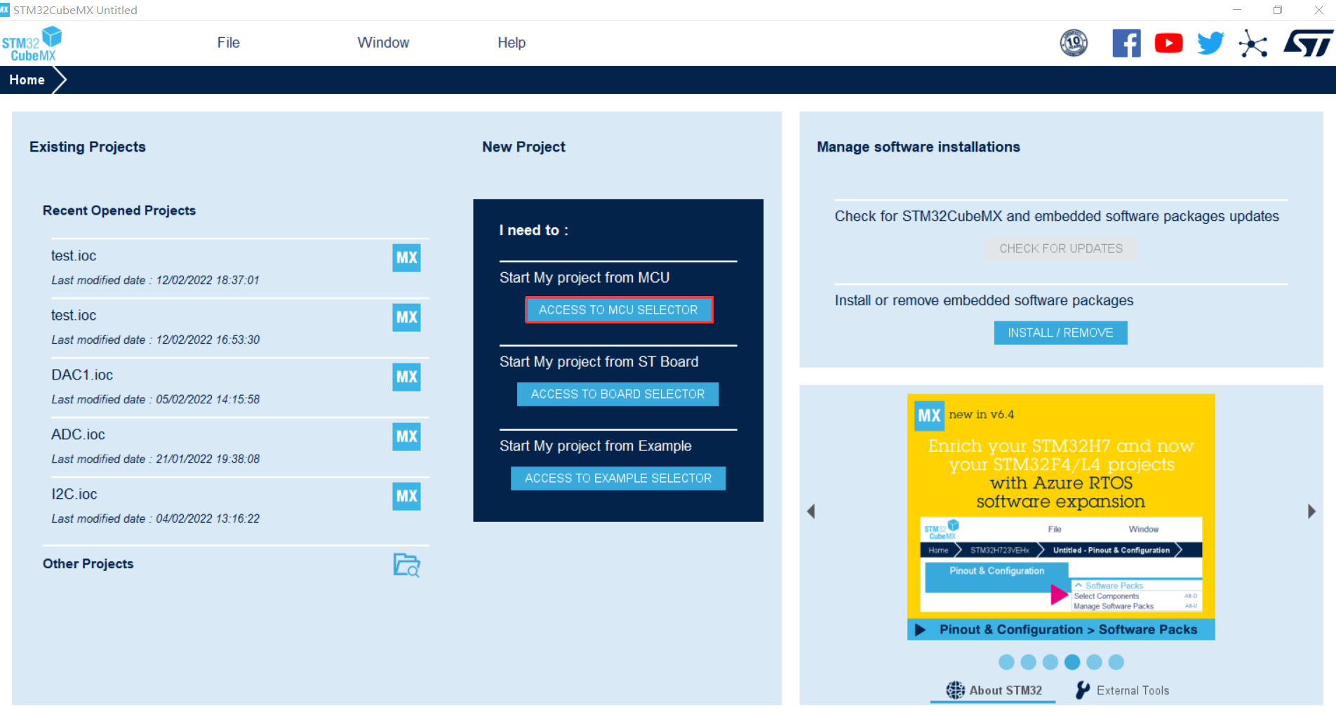
Open stm32cubemx and click the red box to start the new project
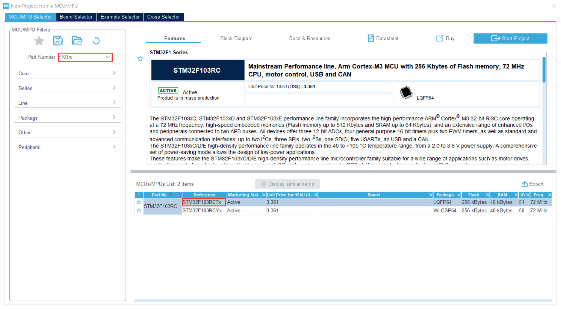
 Find the chip model, select the corresponding chip model and double-click
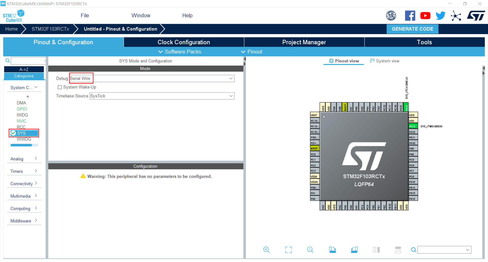
Configure sys as follows to facilitate st link download
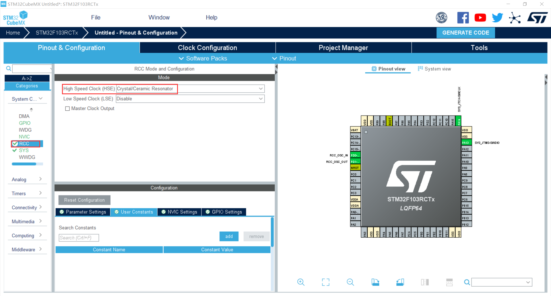
Set rcc and select high speed clock (HSE) as external crystal oscillator
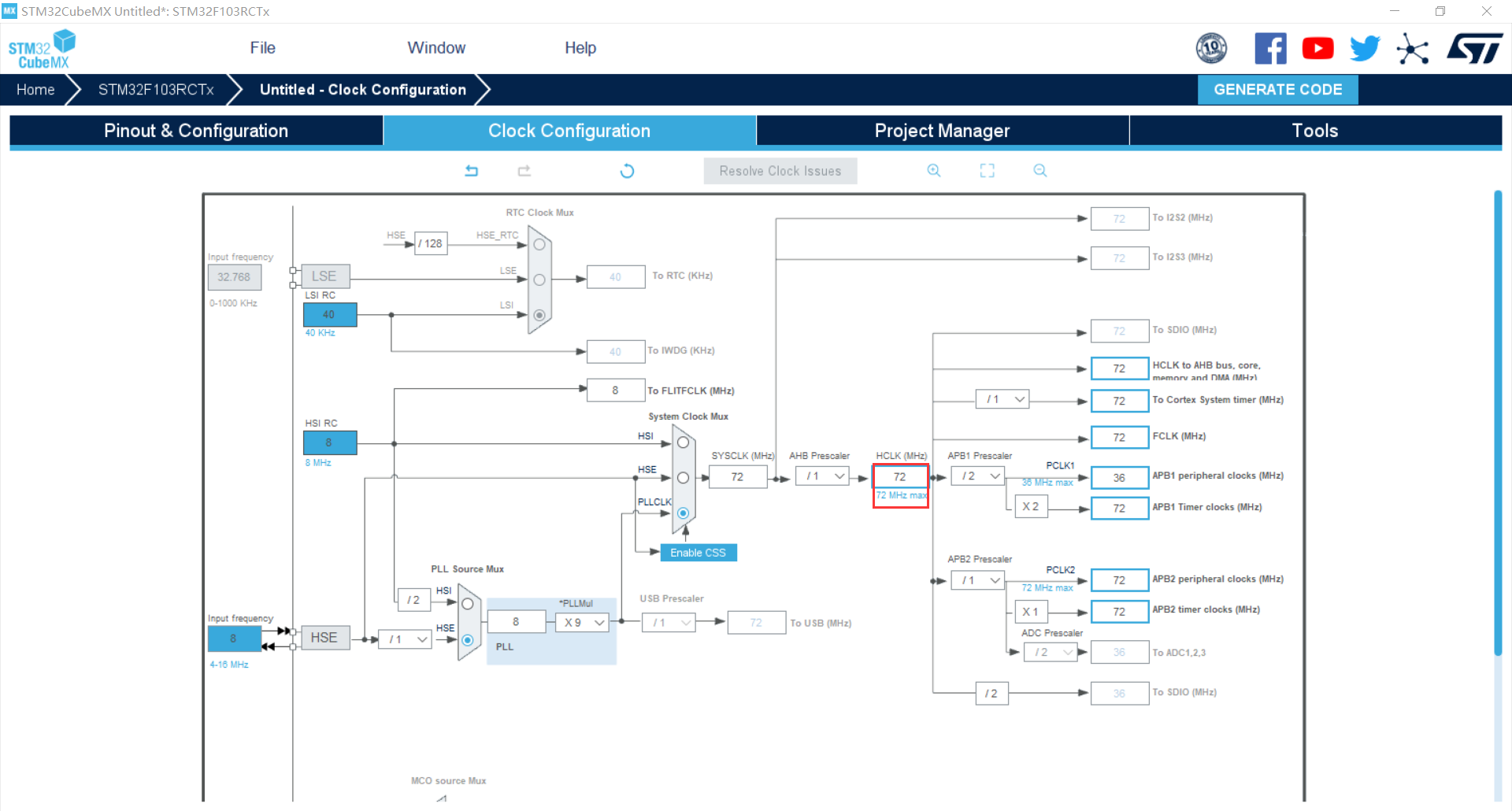
To configure the clock tree, f103 series is used in this paper, and the maximum HCLK is 72MHz
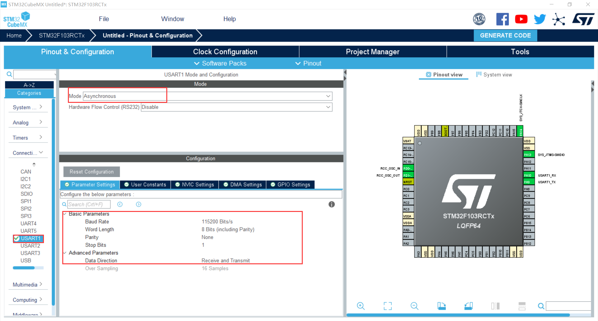
Configure serial port:
1. Set MODE to asynchronous
2. Use the default configuration (the baud rate is 115200 Bits/s, the transmission data length is 8 bits, the parity check is none, the stop bit is 1 Bit, and both reception and transmission are enabled)
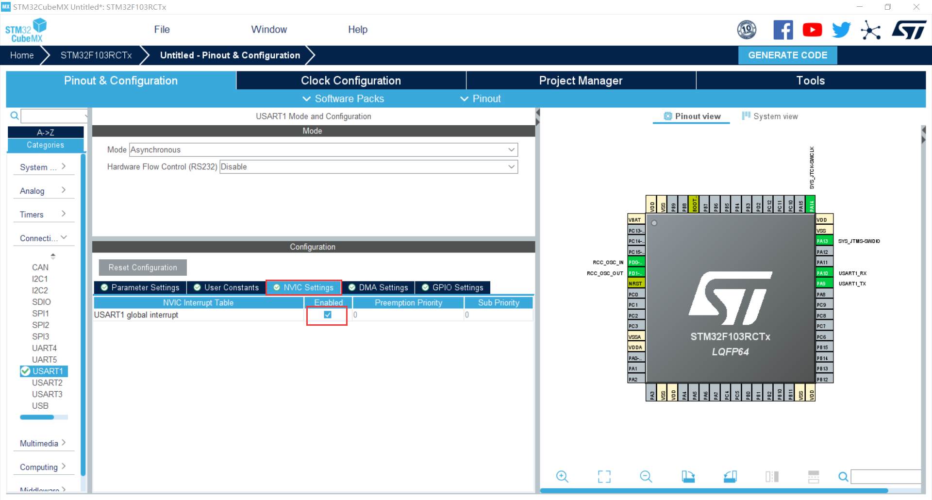
3. Enable serial port interrupt
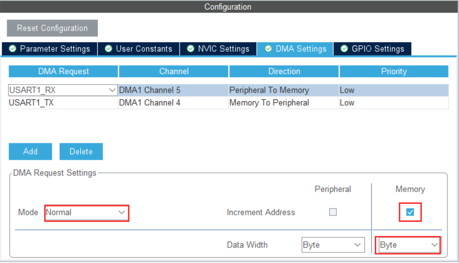
Set DMA:
- Click Add to add the channel
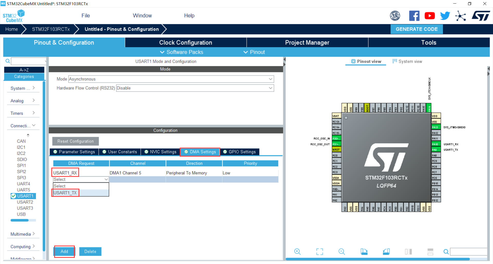
- The channel configuration is the default (the mode is normal, and the memory address is incremented by 1 byte each time)
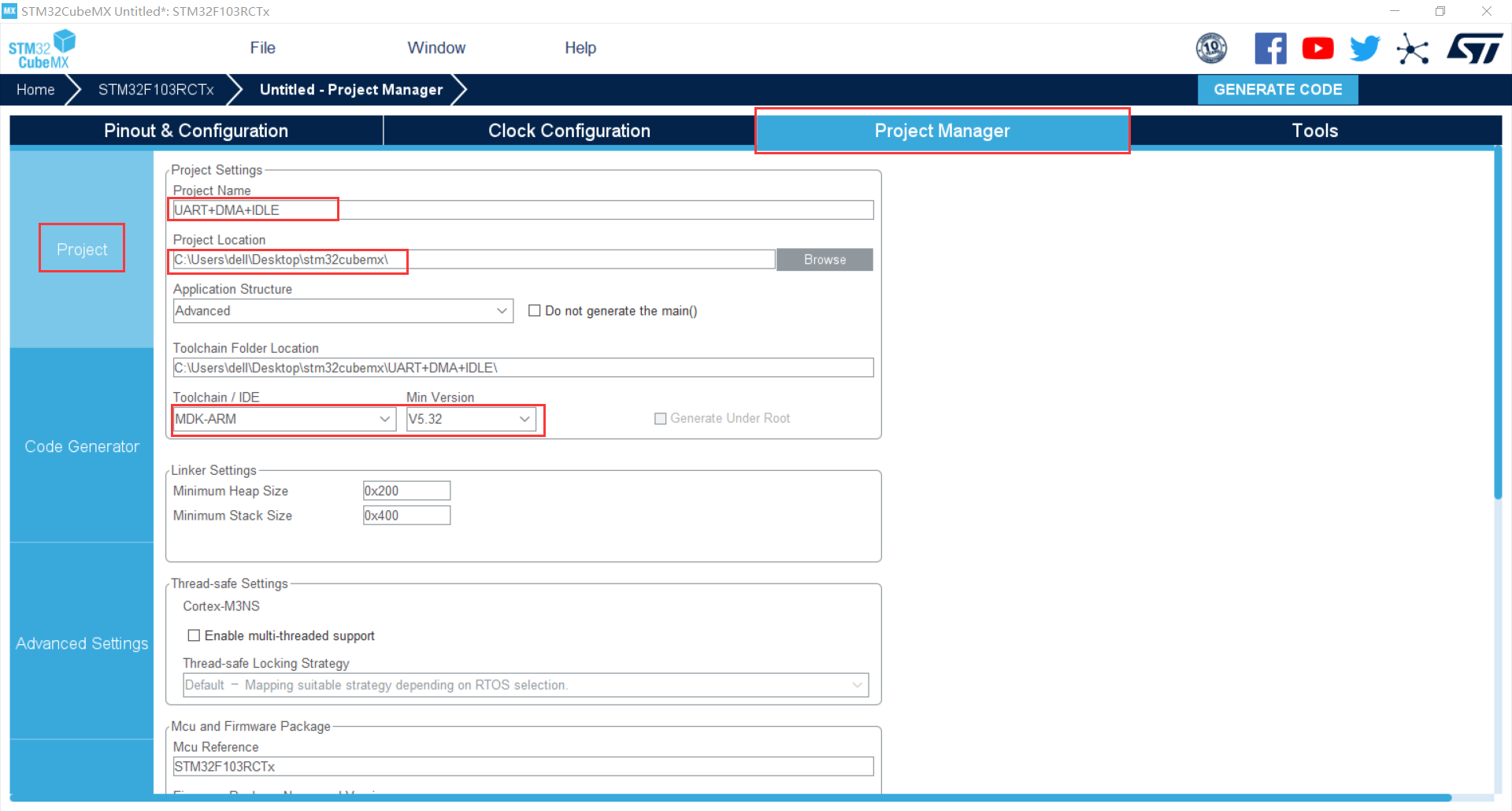
Name the project, select the storage location, and select the compiler and version to use
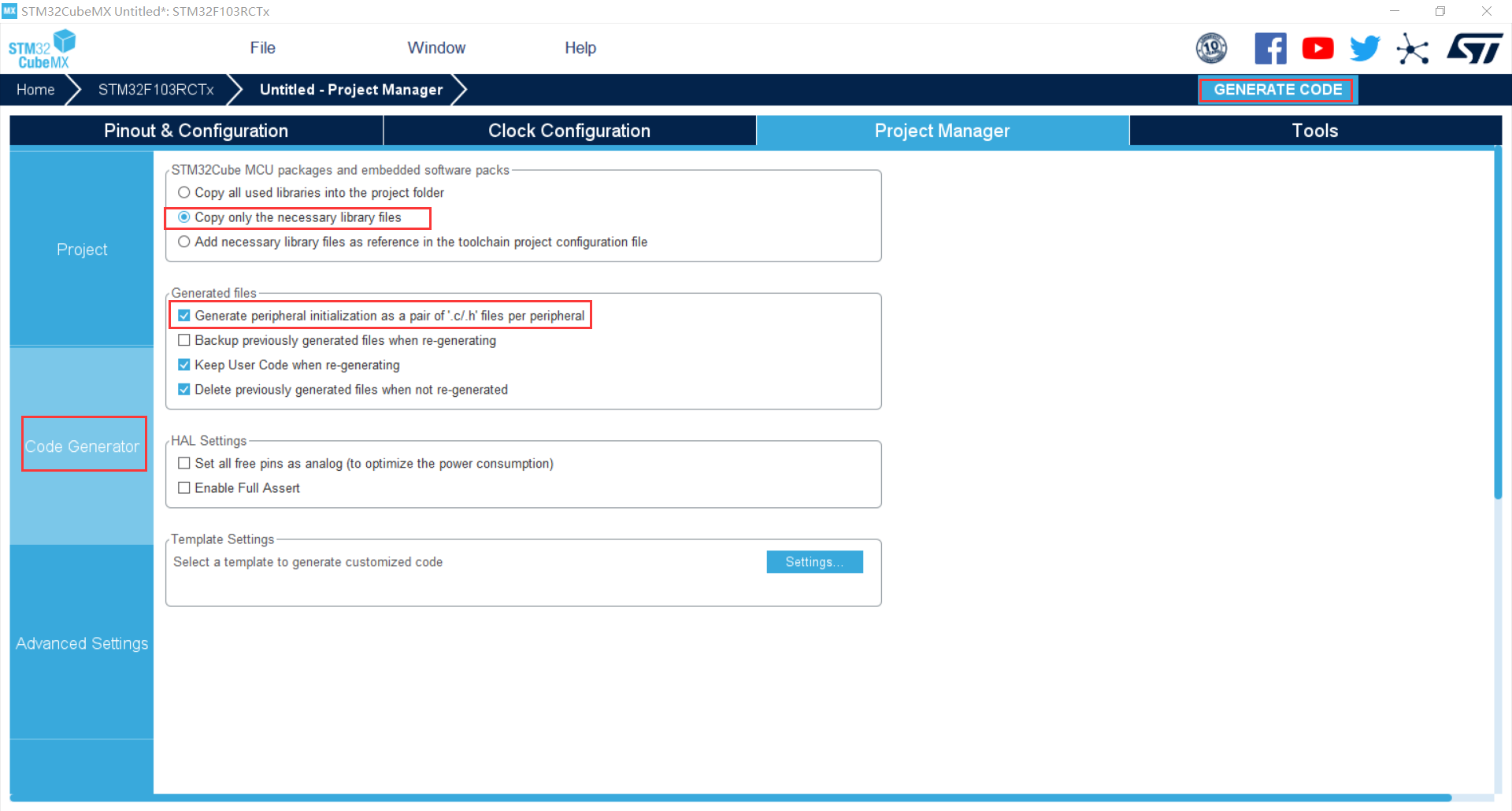
Configure as follows and click GENERATE CODE to GENERATE CODE
Code writing
Note: the double buffer is used to receive data, which can effectively prevent the reception interrupt interval from being very short (i.e. the rate of sending data frames is very fast), and the MCU has no time to process the received data, resulting in an interrupt, resulting in the data being overwritten
main. Add in H
#define BUFFER_SIZE  100
extern  volatile uint8_t rxlen ;  //The length of a frame of data received
void USAR_UART_IDLECallback(UART_HandleTypeDef *huart,uint8_t rxlen );
main.c
/* USER CODE BEGIN PV */
volatile uint8_t rxlen = 0;  //The length of a frame of data received
uint8_t rxbuffer1[BUFFER_SIZE]={0};  //Receive data cache array 1
//uint8_t rxbuffer2[BUFFER_SIZE]={0};  // Receive data cache array 2
//uint8_t flag=0; Double buffer switching flag
/* USER CODE END PV */
In the main function, pay attention to ensure that the DMA initialization function is placed before the serial port initialization,
After serial port initialization, enable IDLE interrupt and enable serial port DMA reception
 /* Initialize all configured peripherals */
  MX_GPIO_Init();
  MX_DMA_Init();//Before serial port initialization
  MX_USART1_UART_Init();

  /* USER CODE BEGIN 2 */
  __HAL_UART_ENABLE_IT(&huart1, UART_IT_IDLE); //Enable IDLE interrupt
   HAL_UART_Receive_DMA(&huart1,rxbuffer1,BUFFER_SIZE);//Enable serial port DMA reception
  /* USER CODE END 2 */
Add the user-defined IDLE interrupt callback function under / * USER CODE BEGIN 4 * / (the comment part is double buffered reception)
void USAR_UART_IDLECallback(UART_HandleTypeDef *huart,uint8_t rxlen )
	{
	if(huart == &huart1)  //Judge whether the serial port 1 is interrupted
	{
 /*		switch(flag)
 	{
			case 0:	flag=1;
				    HAL_UART_Transmit_DMA(&huart1, rxbuffer1,rxlen);//Send the received indefinite length data to the upper computer
	                memset(rxbuffer2,0,BUFFER_SIZE);//Empty the acceptance cache, and the call needs to contain string h
			        rxlen = 0;//Clear data length count
					HAL_UART_Receive_DMA(&huart1,rxbuffer2,BUFFER_SIZE);//Reopen DMA reception
 		    break;
			case 1:flag=0;
			       HAL_UART_Transmit_DMA(&huart1, rxbuffer2,rxlen);//Send the received indefinite length data to the upper computer
	               memset(rxbuffer1,0,BUFFER_SIZE);//Empty the acceptance cache, and the call needs to contain string h
			       rxlen = 0;//Clear data length count
				   HAL_UART_Receive_DMA(&huart1,rxbuffer1,BUFFER_SIZE);//Reopen DMA reception
			break;
			}*/

         HAL_UART_Transmit_DMA(&huart1, rxbuffer1,rxlen);//Send the received indefinite length data to the upper computer
	     rxlen = 0;//Clear data length count
		 HAL_UART_Receive_DMA(&huart1,rxbuffer1,BUFFER_SIZE);//Reopen DMA reception
	}

	}
Since there is no interrupt processing function for IDLE interrupt defined in hal library, it needs to be defined by the user
Open stm32f1xx_it.c. Void usart1 found_ Irqhandler (void) function and add the following code:
void USART1_IRQHandler(void)
{
/* USER CODE BEGIN USART1_IRQn 0 */
/* USER CODE END USART1_IRQn 0 */
HAL_UART_IRQHandler(&huart1);
/* USER CODE BEGIN USART1_IRQn 1 */
if(RESET != __HAL_UART_GET_FLAG(&huart1, UART_FLAG_IDLE)) //Judge whether the idle flag is set
{
__HAL_UART_CLEAR_IDLEFLAG(&huart1);//Clear flag bit
HAL_UART_DMAStop(&huart1); // Stop DMA transfer
rxlen = BUFFER_SIZE - __HAL_DMA_GET_COUNTER(&hdma_usart1_rx); //The total count subtracts the number of untransmitted data to obtain the number of received data
USAR_UART_IDLECallback(&huart1,rxlen); // Call user-defined idle interrupt callback function
}
/* USER CODE END USART1_IRQn 1 */
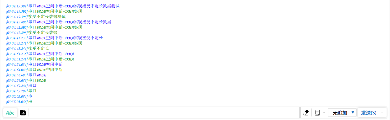
}Download program test
Blue indicates that the upper computer sends data, and green indicates that the upper computer receives data
The test is normal