Note: This series blog was translated from Nathan Vaughn's Shaders Language Tutorial and has been authorized by the author. If reprinted or reposted, please be sure to mark the original link and description in the key position of the article after obtaining the author's consent as well as the translator's. If the article is helpful to you, click this Donation link to buy the author a cup of coffee.
Note: this series of blog posts is translated from Nathan Vaughn of Shader Language Tutorial . The article has been authorized by the author for translation. If you reprint it, please be sure to obtain it at author and translator After agreeing, indicate the original link and description in the key position of the article. If you think the article is helpful to you, click here Reward link Buy the author a cup of coffee.
Hello, friends! Welcome to Shadertoy's fourteenth tutorial. Have you ever thought about how the complex shapes on Shadertoy are drawn? We have learned how to draw balls and cubes, but how to draw other complex shapes? In this article, we will pass Inigo Quilez At the same time, it is also the SDF operation method provided by the co-founder of Shadertoy to learn how to draw complex shapes.
initialization
Below, we have created a template of ray stepping algorithm, which we have used before. If you need to develop 3D scenes, it will be very useful to you. Let's start:
  const int MAX_MARCHING_STEPS = 255;
const float MIN_DIST = 0.0;
const float MAX_DIST = 100.0;
const float PRECISION = 0.001;
const float EPSILON = 0.0005;
const float PI = 3.14159265359;
const vec3 COLOR_BACKGROUND = vec3(.741, .675, .82);
const vec3 COLOR_AMBIENT = vec3(0.42, 0.20, 0.1);

mat2 rotate2d(float theta) {
  float s = sin(theta), c = cos(theta);
  return mat2(c, -s, s, c);
}

float sdSphere(vec3 p, float r, vec3 offset)
{
  return length(p - offset) - r;
}

float scene(vec3 p) {
  return sdSphere(p, 1., vec3(0, 0, 0));
}

float rayMarch(vec3 ro, vec3 rd) {
  float depth = MIN_DIST;
  float d; // distance ray has travelled

  for (int i = 0; i < MAX_MARCHING_STEPS; i++) {
    vec3 p = ro + depth * rd;
    d = scene(p);
    depth += d;
    if (d < PRECISION || depth > MAX_DIST) break;
  }

  d = depth;

  return d;
}

vec3 calcNormal(in vec3 p) {
    vec2 e = vec2(1, -1) * EPSILON;
    return normalize(
      e.xyy * scene(p + e.xyy) +
      e.yyx * scene(p + e.yyx) +
      e.yxy * scene(p + e.yxy) +
      e.xxx * scene(p + e.xxx));
}

mat3 camera(vec3 cameraPos, vec3 lookAtPoint) {
	vec3 cd = normalize(lookAtPoint - cameraPos);
	vec3 cr = normalize(cross(vec3(0, 1, 0), cd));
	vec3 cu = normalize(cross(cd, cr));

	return mat3(-cr, cu, -cd);
}

void mainImage( out vec4 fragColor, in vec2 fragCoord )
{
  vec2 uv = (fragCoord-.5*iResolution.xy)/iResolution.y;
  vec2 mouseUV = iMouse.xy/iResolution.xy;

  if (mouseUV == vec2(0.0)) mouseUV = vec2(0.5); // trick to center mouse on page load

  vec3 col = vec3(0);
  vec3 lp = vec3(0);
  vec3 ro = vec3(0, 0, 3); // ray origin that represents camera position

  float cameraRadius = 2.;
  ro.yz = ro.yz * cameraRadius * rotate2d(mix(-PI/2., PI/2., mouseUV.y));
  ro.xz = ro.xz * rotate2d(mix(-PI, PI, mouseUV.x)) + vec2(lp.x, lp.z);

  vec3 rd = camera(ro, lp) * normalize(vec3(uv, -1)); // ray direction

  float d = rayMarch(ro, rd); // signed distance value to closest object

  if (d > MAX_DIST) {
    col = COLOR_BACKGROUND; // ray didn't hit anything
  } else {
    vec3 p = ro + rd * d; // point discovered from ray marching
    vec3 normal = calcNormal(p); // surface normal

    vec3 lightPosition = vec3(0, 2, 2);
    vec3 lightDirection = normalize(lightPosition - p) * .65; // The 0.65 is used to decrease the light intensity a bit

    float dif = clamp(dot(normal, lightDirection), 0., 1.) * 0.5 + 0.5; // diffuse reflection mapped to values between 0.5 and 1.0

    col = vec3(dif) + COLOR_AMBIENT;
  }

  fragColor = vec4(col, 1.0);
}
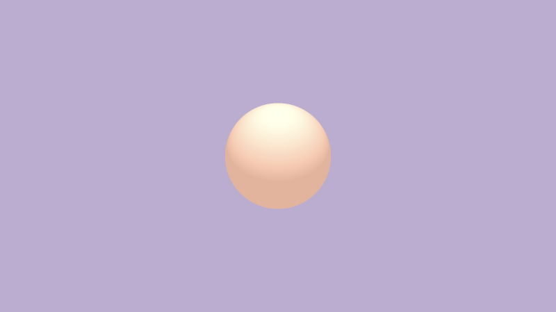
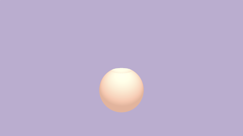
Run the above code and you can see a ball on the screen.
Let's analyze this code to find out how the ray stepping algorithm works. At the top of the code, we define constants that we The sixth tutorial I saw it in.
const int MAX_MARCHING_STEPS = 255;
const float MIN_DIST = 0.0;
const float MAX_DIST = 100.0;
const float PRECISION = 0.001;
const float EPSILON = 0.0005;
const float PI = 3.14159265359;
const vec3 COLOR_BACKGROUND = vec3(.741, .675, .82);
const vec3 COLOR_AMBIENT = vec3(0.42, 0.20, 0.1);
We store the background color and ambient light color by defining variables, so that we can quickly change the color of 3D objects. Next, we will define a rotate2d function, which is used to rotate the object on the 2D plane Tutorial 10 This has been discussed in. We will use this function to move the 3D model with the mouse.
  mat2 rotate2D(float theta) {
    float s = sin(theta), c = cos(theta);
    return mat2(c, -s, s, c);
  }
The next function used is the basic tool function for creating 3D scenes. We are The sixth tutorial I learned it for the first time. The sdSphere function is a symbolic distance field function (SDF) used to create a ball. The scene function is used to render all objects in the scene. If you have read the code on Shadertoy, the scene function is also named map function.
  float sdSphere(vec3 p, float r, vec3 offset)
{
  return length(p - offset) - r;
}

float scene(vec3 p) {
  return sdSphere(p, 1., vec3(0));
}

float rayMarch(vec3 ro, vec3 rd) {
  float depth = MIN_DIST;
  float d; // distance ray has travelled

  for (int i = 0; i < MAX_MARCHING_STEPS; i++) {
    vec3 p = ro + depth * rd;
    d = scene(p);
    depth += d;
    if (d < PRECISION || depth > MAX_DIST) break;
  }

  d = depth;

  return d;
}

vec3 calcNormal(in vec3 p) {
    vec2 e = vec2(1, -1) * EPSILON;
    return normalize(
      e.xyy * scene(p + e.xyy) +
      e.yyx * scene(p + e.yyx) +
      e.yxy * scene(p + e.yxy) +
      e.xxx * scene(p + e.xxx));
}
Next, we created the camera function to define the camera model through an observation target point. We also discussed this point Tutorial 10 Mentioned in. Use the target observation point camera to focus on a target.
  mat3 camera(vec3 cameraPos, vec3 lookAtPoint) {
	vec3 cd = normalize(lookAtPoint - cameraPos);
	vec3 cr = normalize(cross(vec3(0, 1, 0), cd));
	vec3 cu = normalize(cross(cd, cr));

	return mat3(-cr, cu, -cd);
}
Now let's analyze the mainImage function. Reset the UV coordinates so that the pixel coordinates can be controlled between - 0.5 and 0.5. We also need to calculate the azimuth ratio so that the value of the x axis will be between integers and negative numbers.
vec2 uv = (fragCoord-.5*iResolution.xy)/iResolution.y;
Since we use the mouse to rotate 3D objects, we need to set mouseUV coordinates. When the mouse clicks on the screen, we set its coordinates between 0 and 1.
vec2 mouseUV = iMouse.xy/iResolution.xy;
There is another problem here. When we publish shader code on Shadertoy and the user loads our code for the first time, the coordinates will take the initial value (0,0) as the coordinates of mouseUV. We can use a trick to fix this small defect by assigning a new value to it.
if (mouseUV == vec2(0.0)) mouseUV = vec2(0.5); // trick to center mouse on page load
Next, we declare a color variable, col, which can be set arbitrarily. Then we need to set the target observation point, lp, and the ray source, ro, which we are in Tutorial 10 Discussed in. Our ball is not offset in the field at present. Its position is vec2(0,0). We should keep the target observation point in this position, of course, we can adjust it at will.
vec3 col = vec3(0);
vec3 lp = vec3(0); // lookat point
vec3 ro = vec3(0, 0, 3); // ray origin that represents camera position
Use the mouse to rotate the camera, but pay attention to the distance between the camera and the 3D object Tutorial 10 As a middle school student, use the rate2d function to rotate the camera at a distance from the object cameraRadius.
float cameraRadius = 2.;
ro.yz = ro.yz * cameraRadius * rotate2d(mix(-PI/2., PI/2., mouseUV.y));
ro.xz = ro.xz * rotate2d(mix(-PI, PI, mouseUV.x)) + vec2(lp.x, lp.z);

vec3 rd = camera(ro, lp) * normalize(vec3(uv, -1)); // ray direction
It looks almost done! In addition, there are many ways to move the camera. Different people use it in different ways. You just need to choose the way you like.
Merging of 3D objects
We have understood the meaning of the code provided above. Now let's start some 3D merging operations. I've been there before The fifth tutorial Some 2d operations have been mentioned in. In fact, 3D operations are similar to them. We will use some tool functions to combine objects or cut them. These functions are OK Inigo Quilez 3D Found on the web page. Let's define some tool functions on top of the scene function.
Union: combine multiple figures together, or draw multiple figures on a screen at the same time. We should be familiar with this function. We used it to draw multiple objects on the screen before.
float opUnion(float d1, float d2) {
  return min(d1, d2);
}

float scene(vec3 p) {
  float d1 = sdSphere(p, 1., vec3(0, -1, 0));
  float d2 = sdSphere(p, 0.75, vec3(0, 0.5, 0));
  return opUnion(d1, d2);
}

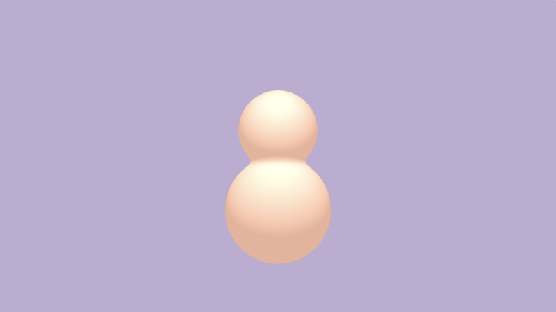
Smooth Union: the two objects are smoothly combined together, and then the combined edge smoothness is processed through the parameter k. K is equal to 0, indicating that the smoothness is 0, i.e. normal combination.
  float opSmoothUnion(float d1, float d2, float k) {
  float h = clamp( 0.5 + 0.5*(d2-d1)/k, 0.0, 1.0 );
  return mix( d2, d1, h ) - k*h*(1.0-h);
}

float scene(vec3 p) {
  float d1 = sdSphere(p, 1., vec3(0, -1, 0));
  float d2 = sdSphere(p, 0.75, vec3(0, 0.5, 0));
  return opSmoothUnion(d1, d2, 0.2);
}
Intersection: take the intersection of two figures
  float opIntersection(float d1, float d2) {
  return max(d1,d2);
}

float scene(vec3 p) {
  float d1 = sdSphere(p, 1., vec3(0, -1, 0));
  float d2 = sdSphere(p, 0.75, vec3(0, 0.5, 0));
  return opIntersection(d1, d2);
}

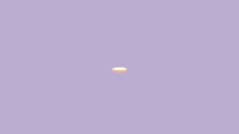
Smooth Intersection: combines two objects and uses the k value to determine the degree of edge fusion. 0 means no fusion.
  float opSmoothIntersection(float d1, float d2, float k) {
  float h = clamp( 0.5 - 0.5*(d2-d1)/k, 0.0, 1.0 );
  return mix( d2, d1, h ) + k*h*(1.0-h);
}

float scene(vec3 p) {
  float d1 = sdSphere(p, 1., vec3(0, -1, 0));
  float d2 = sdSphere(p, 0.75, vec3(0, 0.5, 0));
  return opSmoothIntersection(d1, d2, 0.2);
}
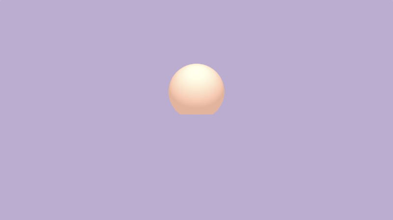
Clipping: clipping d2 with d1
  float opSubtraction(float d1, float d2 ) {
  return max(-d1, d2);
}

float scene(vec3 p) {
  float d1 = sdSphere(p, 1., vec3(0, -1, 0));
  float d2 = sdSphere(p, 0.75, vec3(0, 0.5, 0));
  return opSubtraction(d1, d2);
}
Smooth Subtraction: use d1 to clip d2, and use the smooth edge parameter k.
  float opSmoothSubtraction(float d1, float d2, float k) {
  float h = clamp( 0.5 - 0.5*(d2+d1)/k, 0.0, 1.0 );
  return mix( d2, -d1, h ) + k*h*(1.0-h);
}

float scene(vec3 p) {
  float d1 = sdSphere(p, 1., vec3(0, -1, 0));
  float d2 = sdSphere(p, 0.75, vec3(0, 0.5, 0));
  return opSmoothSubtraction(d1, d2, 0.2);
}

Reverse crop 2: Crop d1 with d2
  float opSubtraction2(float d1, float d2 ) {
  return max(d1, -d2);
}

float scene(vec3 p) {
  float d1 = sdSphere(p, 1., vec3(0, -1, 0));
  float d2 = sdSphere(p, 0.75, vec3(0, 0.5, 0));
  return opSubtraction2(d1, d2);
}
Smooth Subtraction 2: clip d1 from d2, using the smoothing value k.
float opSmoothSubtraction2(float d1, float d2, float k) {
  float h = clamp( 0.5 - 0.5*(d2+d1)/k, 0.0, 1.0 );
  return mix( d1, -d2, h ) + k*h*(1.0-h);
}

float scene(vec3 p) {
  float d1 = sdSphere(p, 1., vec3(0, -1, 0));
  float d2 = sdSphere(p, 0.75, vec3(0, 0.5, 0));
  return opSmoothSubtraction2(d1, d2, 0.2);
}
3D positioning
Inigo Quilez's 3D SDFs The web page describes a series of 3D SDF operations, which can help us save a lot of time when drawing 3D objects. Some operations can also improve performance because we don't need to repeatedly use the ray stepping function.
We have learned before that if we use the transformation matrix to rotate a figure and move a 3D object to a certain distance at the same time. If you need to scale a graph, you can simply modify the dimension of SDF.
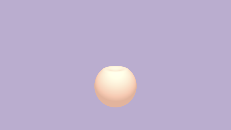
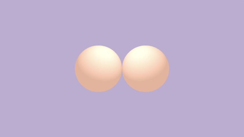
If you need to draw symmetrical scenes, you need to use opSymx operation. This method will create a symmetrical 3D object along the X axis. If the ball you draw is at the position of vec3(1,0,0), then at the position of vec3 (- 1,0,0), we will get another ball;
  float opSymX(vec3 p, float r, vec3 o)
{
  p.x = abs(p.x);
  return sdSphere(p, r, o);
}

float scene(vec3 p) {
  return opSymX(p, 1., vec3(1, 0, 0));
}
If you want to do symmetry along the Y or Z axis, you just need to replace p.x with p.y or p.z. Also remember to adjust your offset value at the same time.
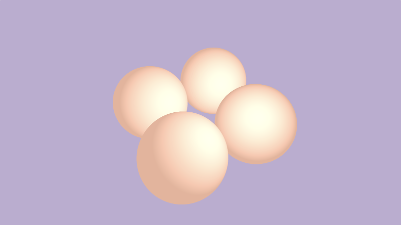
If you want to draw a sphere along two axes instead of one, you can use the opSymXZ function, which will create an object on the XZ plane, and the result is four balls. If we draw a ball at the position of vec3 (1,0,1), a ball will appear at the positions of vec3(1,0,1), vec3(-1,0,1), vec3(1,0,-1) and vec3 (- 1,0, - 1).
  float opSymXZ(vec3 p, float r, vec3 o)
{
  p.xz = abs(p.xz);
  return sdSphere(p, r, o);
}

float scene(vec3 p) {
  return opSymXZ(p, 1., vec3(1, 0, 1));
}
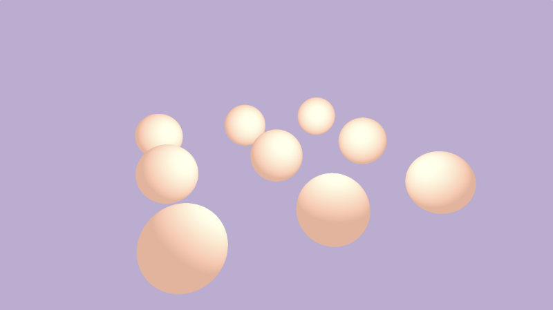
If you want to create an unlimited number of 3D object effects along multiple axes, you can use the opRep function to achieve this effect. Parameter, c, is used to control the spacing of objects in 3D space on each axis.
  float opRep(vec3 p, float r, vec3 o, vec3 c)
{
  vec3 q = mod(p+0.5*c,c)-0.5*c;
  return sdSphere(q, r, o);
}

float scene(vec3 p) {
  return opRep(p, 1., vec3(0), vec3(8));
}

If you want to create a limited number of 3D objects on the axis, use the opRepLim function. Parameter c still represents the spacing, and parameter l represents the number of objects on the axis. For example, vec3(1,0,1) can draw a sphere along the positive and negative directions of the x and z axes.
  float opRepLim(vec3 p, float r, vec3 o, float c, vec3 l)
{
  vec3 q = p-c*clamp(round(p/c),-l,l);
  return sdSphere(q, r, o);
}

float scene(vec3 p) {
  return opRepLim(p, 0.5, vec3(0), 2., vec3(1, 0, 1));
}
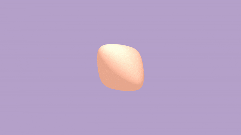
Adding p to the calculation result of SDF and arbitrarily modifying P can make the object deform and distort. In the opplace function, you can modify this value arbitrarily to create various mathematical effects.
  float opDisplace(vec3 p, float r, vec3 o)
{
  float d1 = sdSphere(p, r, o);
  float d2 = sin(p.x)*sin(p.y)*sin(p.z) * cos(iTime);
  return d1 + d2;
}

float scene(vec3 p) {
  return opDisplace(p, 1., vec3(0));
}
Here is the complete code shown in:
  const int MAX_MARCHING_STEPS = 255;
const float MIN_DIST = 0.0;
const float MAX_DIST = 100.0;
const float PRECISION = 0.001;
const float EPSILON = 0.0005;
const float PI = 3.14159265359;
const vec3 COLOR_BACKGROUND = vec3(.741, .675, .82);
const vec3 COLOR_AMBIENT = vec3(0.42, 0.20, 0.1);

mat2 rotate2d(float theta) {
  float s = sin(theta), c = cos(theta);
  return mat2(c, -s, s, c);
}

float sdSphere(vec3 p, float r, vec3 offset)
{
  return length(p - offset) - r;
}

float opUnion(float d1, float d2) {
  return min(d1, d2);
}

float opSmoothUnion(float d1, float d2, float k) {
  float h = clamp( 0.5 + 0.5*(d2-d1)/k, 0.0, 1.0 );
  return mix( d2, d1, h ) - k*h*(1.0-h);
}

float opIntersection(float d1, float d2) {
  return max(d1, d2);
}

float opSmoothIntersection(float d1, float d2, float k) {
  float h = clamp( 0.5 - 0.5*(d2-d1)/k, 0.0, 1.0 );
  return mix( d2, d1, h ) + k*h*(1.0-h);
}

float opSubtraction(float d1, float d2) {
  return max(-d1, d2);
}

float opSmoothSubtraction(float d1, float d2, float k) {
  float h = clamp( 0.5 - 0.5*(d2+d1)/k, 0.0, 1.0 );
  return mix( d2, -d1, h ) + k*h*(1.0-h);
}

float opSubtraction2(float d1, float d2) {
  return max(d1, -d2);
}

float opSmoothSubtraction2(float d1, float d2, float k) {
  float h = clamp( 0.5 - 0.5*(d2+d1)/k, 0.0, 1.0 );
  return mix( d1, -d2, h ) + k*h*(1.0-h);
}

float opSymX(vec3 p, float r, vec3 o)
{
  p.x = abs(p.x);
  return sdSphere(p, r, o);
}

float opSymXZ(vec3 p, float r, vec3 o)
{
  p.xz = abs(p.xz);
  return sdSphere(p, r, o);
}

float opRep(vec3 p, float r, vec3 o, vec3 c)
{
  vec3 q = mod(p+0.5*c,c)-0.5*c;
  return sdSphere(q, r, o);
}

float opRepLim(vec3 p, float r, vec3 o, float c, vec3 l)
{
  vec3 q = p-c*clamp(round(p/c),-l,l);
  return sdSphere(q, r, o);
}

float opDisplace(vec3 p, float r, vec3 o)
{
  float d1 = sdSphere(p, r, o);
  float d2 = sin(p.x)*sin(p.y)*sin(p.z) * cos(iTime);
  return d1 + d2;
}

float scene(vec3 p) {
  float d1 = sdSphere(p, 1., vec3(0, -1, 0));
  float d2 = sdSphere(p, 0.75, vec3(0, 0.5, 0));
  //return d1;
  //return d2;
  //return opUnion(d1, d2);
  //return opSmoothUnion(d1, d2, 0.2);
  //return opIntersection(d1, d2);
  //return opSmoothIntersection(d1, d2, 0.2);
  //return opSubtraction(d1, d2);
  //return opSmoothSubtraction(d1, d2, 0.2);
  //return opSubtraction2(d1, d2);
  //return opSmoothSubtraction2(d1, d2, 0.2);
  //return opSymX(p, 1., vec3(1, 0, 0));
  //return opSymXZ(p, 1., vec3(1, 0, 1));
  //return opRep(p, 1., vec3(0), vec3(8));
  //return opRepLim(p, 0.5, vec3(0), 2., vec3(1, 0, 1));
  return opDisplace(p, 1., vec3(0));
}

float rayMarch(vec3 ro, vec3 rd) {
  float depth = MIN_DIST;
  float d; // distance ray has travelled

  for (int i = 0; i < MAX_MARCHING_STEPS; i++) {
    vec3 p = ro + depth * rd;
    d = scene(p);
    depth += d;
    if (d < PRECISION || depth > MAX_DIST) break;
  }

  d = depth;

  return d;
}

vec3 calcNormal(in vec3 p) {
    vec2 e = vec2(1, -1) * EPSILON;
    return normalize(
      e.xyy * scene(p + e.xyy) +
      e.yyx * scene(p + e.yyx) +
      e.yxy * scene(p + e.yxy) +
      e.xxx * scene(p + e.xxx));
}

mat3 camera(vec3 cameraPos, vec3 lookAtPoint) {
	vec3 cd = normalize(lookAtPoint - cameraPos);
	vec3 cr = normalize(cross(vec3(0, 1, 0), cd));
	vec3 cu = normalize(cross(cd, cr));

	return mat3(-cr, cu, -cd);
}

void mainImage( out vec4 fragColor, in vec2 fragCoord )
{
  vec2 uv = (fragCoord-.5*iResolution.xy)/iResolution.y;
  vec2 mouseUV = iMouse.xy/iResolution.xy;

  if (mouseUV == vec2(0.0)) mouseUV = vec2(0.5); // trick to center mouse on page load

  vec3 col = vec3(0);
  vec3 lp = vec3(0);
  vec3 ro = vec3(0, 0, 3); // ray origin that represents camera position

  float cameraRadius = 2.;
  ro.yz = ro.yz * cameraRadius * rotate2d(mix(-PI/2., PI/2., mouseUV.y));
  ro.xz = ro.xz * rotate2d(mix(-PI, PI, mouseUV.x)) + vec2(lp.x, lp.z);

  vec3 rd = camera(ro, lp) * normalize(vec3(uv, -1)); // ray direction

  float d = rayMarch(ro, rd); // signed distance value to closest object

  if (d > MAX_DIST) {
    col = COLOR_BACKGROUND; // ray didn't hit anything
  } else {
    vec3 p = ro + rd * d; // point discovered from ray marching
    vec3 normal = calcNormal(p); // surface normal

    vec3 lightPosition = vec3(0, 2, 2);
    vec3 lightDirection = normalize(lightPosition - p) * .65; // The 0.65 is used to decrease the light intensity a bit

    float dif = clamp(dot(normal, lightDirection), 0., 1.) * 0.5 + 0.5; // diffuse reflection mapped to values between 0.5 and 1.0

    col = vec3(dif) + COLOR_AMBIENT;
  }

  fragColor = vec4(col, 1.0);
}
summary
Through this tutorial, we learned the deformation of various 3D objects, such as unions, intersections, and subtracts. At the same time, I learned to use the "positive" method to draw the same figure on different axes. Some of the resources below include one I created Template code for ray stepping , as well as some of the above 3D SDF function operation . What is discussed here is only a small part of SDF operations, and there are many other operations that you need to access Inigo Quilez's website To learn.
resources
Ray Marching Template
3D SDF Operations
Combination
Elongation
Rounding
Onion
Metric
Repetition
Extrusion2D
Revolution2D
Ray Marching Primitives
Ray Marching Primitives Commented