In our products, we often need to test the temperature and humidity data. There are many methods and modules to detect temperature and humidity, among which SHT1x series temperature and humidity sensor is a low cost and easy to use temperature and humidity detection module. Let's talk about how to realize the driving of SHT1x series temperature and humidity sensor.
1. Function overview
SHT1x includes SHT10, SHT11 and SHT15, which belong to the chip package series of Sensirion temperature and humidity sensor family. The sensor integrates the sensing element and signal processing circuit into a micro circuit board, and outputs a fully calibrated digital signal.
1.1 hardware description
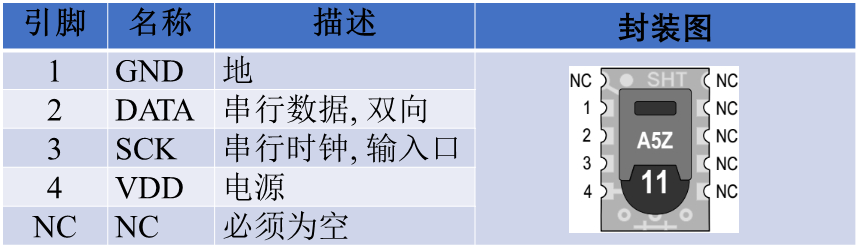
SHT1x sensor consists of a capacitive polymer humidity sensor and a temperature sensor made of energy gap material. It is connected seamlessly with 14 bit A/D converter and serial interface circuit on the same chip. Its pin is defined as follows:
SHT1x temperature and humidity sensor uses two-wire communication, similar to I2C bus, but not the same, using ordinary GPIO can achieve communication. This time, STM32F103VET6 is used to operate SHT15. The specific connection mode is as follows:
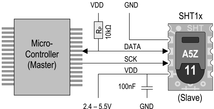
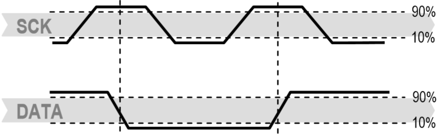
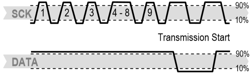
SCK is used for communication synchronization between microprocessor and SHT1x. Because the interface contains full static logic, there is no minimum SCK frequency.
The DATA pin is a three state structure, which is used to read the sensor DATA. When sending commands to the sensor, DATA is valid at the rising edge of SCK and must be stable at high power level of SCK. DATA changes after the falling edge of SCK. To avoid signal conflict, the microprocessor shall drive DATA at low level. An external pull-up resistor (e.g. 10k Ω) is required to raise the signal to high level. Pull-up resistors are usually included in the I/O circuits of microprocessors.
1.2 data communication
After selecting the power supply voltage, power on the sensor, and the power on rate shall not be lower than 1V/ms. After power on, the sensor needs 11ms to enter the sleep state. Before that, it is not allowed to send any command to the sensor.
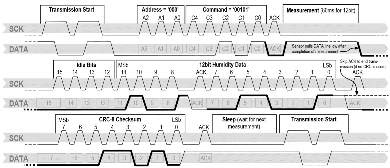
SHT1x temperature and humidity sensor uses a set of "start transmission" time sequence to complete the initialization of DATA transmission. The subsequent commands contain three address bits (currently only supported for 000), and five command bits. SHT1x will indicate that the instruction has been received correctly in the following way: after the falling edge of the 8th SCK clock, pull down the DATA to the low level (ACK bit). Release DATA after the falling edge of the 9th SCK clock. The command table of SHT1x temperature and humidity sensor is as follows:
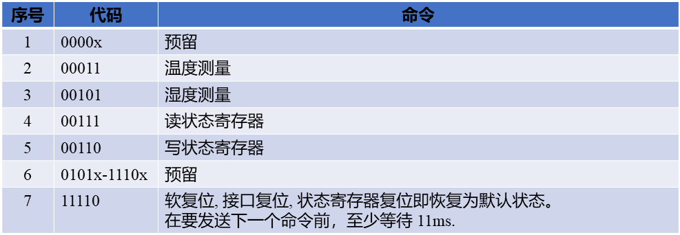
Later, when we develop the SHT1x temperature and humidity sensor driver, we use these operation commands to achieve different operations.
1.3 data calculation
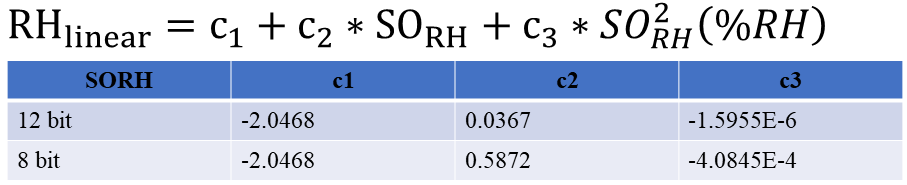
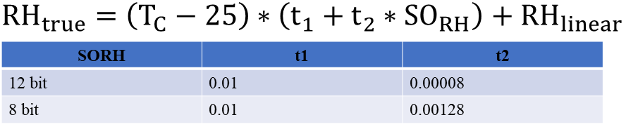
The measurement data of humidity is not a non-linear process of linear change. In order to obtain more accurate measurement data, we usually use the non-linear compensation formula for signal conversion. The nonlinear compensation formula and parameters of humidity are as follows:
Generally speaking, the sensor humidity calibration is carried out under a certain reference temperature, but in our use process, the actual temperature is obviously different from the test reference temperature of 25 ℃ (~ 77 ℉), so we need to compensate the actual humidity data. The temperature compensation formula and coefficient of humidity are as follows:
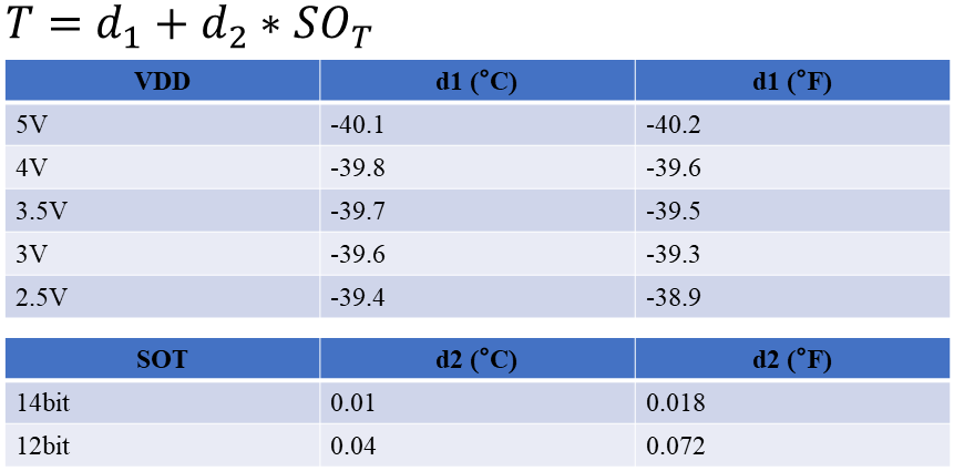
The temperature sensor of SHT1x series temperature and humidity sensor adopts the energy gap material PTAT. The gap material PTAT is generally proportional to the absolute temperature, so the temperature sensor has excellent linearity. The digital output (SOT) can be converted to the temperature value by the following formula, and the temperature conversion coefficient is as follows:
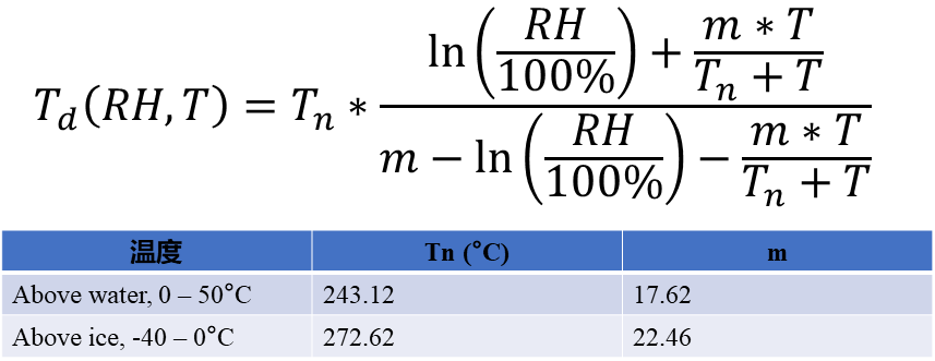
SHT1x does not directly measure the dew point, but the dew point can be calculated from the temperature and humidity readings. Since temperature and humidity are measured on the same IC, SHT1x measures dew point. There are many calculation methods of dew point, most of them are very complex. For the measurement in the temperature range of - 40 – 50 ° C, a better accuracy can be obtained by the following formula.
The temperature, humidity and dew point data monitored by SHT1x can be calculated by the above formulas.
2. Drive design and Implementation
We have understood the basic technical characteristics of SHT1x series temperature and humidity sensor. Next, we will further consider how to design and implement the driver of SHT1x series temperature and humidity sensor.
2.1 object definition
We need to get an object before using it. Similarly, if we want SHT1x series temperature and humidity sensor, we need to define the object of SHT1x series temperature and humidity sensor first.
2.1.1 abstraction of objects
In order to get SHT1x series temperature and humidity sensor object, we need to analyze its basic characteristics first. Generally speaking, an object contains at least two characteristics: properties and operations. Next, we will think about the object of SHT1x series temperature and humidity sensor from these two aspects.
Consider attributes first, which must be something used to identify or record the characteristics of an object. Let's consider the object properties of SHT1x series temperature and humidity sensors. First of all, SHT1x series temperature and humidity sensor has a status register, which is used to represent the status and configuration operation characteristics, so we take the data of the read status register as an attribute to identify the SHT1x series temperature and humidity sensor object. According to the data calculation formula of SHT1x series temperature and humidity sensor, we know that the temperature unit and working voltage have a direct impact on the calculation of temperature measurement results, so we also take the temperature unit and working voltage as the attributes of SHT1x series temperature and humidity sensor object, which is used to distinguish the calculation process. In addition, we use the data of temperature, humidity and dew point as attributes to record the current status.
Then we need to consider the operation of sht1x series temperature and humidity sensor. GPIO is used for analog digital communication, so both SCK pin and DATA pin need to control the output, and the implementation of the control function is related to the specific hardware, so we take the function controlling the output of these two pins as the operation of the object. For the DATA pin, we may need to control the direction and read the input, for the same reason, we also regard it as the operation of the object. In addition, we need to control the clock when communicating with sht1x, and the operation waiting is a time operation related to the hardware, so we also regard it as the operation of the object.
Based on the above analysis of SHT1x temperature and humidity sensor, we can define the object types of SHT1x temperature and humidity sensor as follows:
/* Define SHT1x object type */
typedef struct Sht1xObject {
       uint8_t statusReg;                  //Status register
       uint32_t period;                    //SCK clock cycle
       SHT1xTempUnitType tempUnit;         //Temperature unit
       float vdd;                          //working voltage
       float temperature;                  //temperature
       float humidity;                     //humidity
       float dewPoint;                     //the dew point
       SHT1xSetBusPin *SetBusPin;          //Bus operation function
       uint8_t (*ReadSDABit)(void);        //Read data bus function
       void (*SDADirection)(SHT1xIODirectionType direction);       //Data bus direction control function
       void (*Delayus)(volatile uint32_t period);    //Microsecond delay function
       void (*Delayms)(volatile uint32_t nTime);     //Millisecond delay function
}Sht1xObjectType;
2.1.2 object initialization
We know that an object can not be used only for declaration. We need to initialize it first, so let's consider the initialization function of SHT1x series temperature and humidity sensor object. Generally speaking, initialization functions need to deal with several problems. The first is to check whether the input parameters are reasonable; the second is to assign initial values to the attributes of the object; the third is to make necessary initialization configuration for the object. According to this, we design the initialization function of SHT1x series temperature and humidity sensor as follows:
/* Initialize SHT1x object */
void SHT1xInitialization(Sht1xObjectType *sht,
uint32_t sck,
float vdd,
SHT1xTempUnitType uint,
SHT1xHeaterType heater,
SHT1xOTPType otp,
SHT1xResolutionType resolution,
SHT1xSetBusPin setSckPin,
HT1xSetBusPin setDataPin,
SHT1xReadSDABit readSDA,
SHT1xSDADirection direction,
SHT1xDelay delayus,
SHT1xDelay delayms)
{
uint8_t regSetup=0x00;
uint8_t heaterSet[]={ONCHIPHEATERDISABLE,ONCHIPHEATERENABLE}; //Whether to enable the on-chip heating configuration set
uint8_t otpSet[]={OTPENABLE,OTPDISABLE}; //Whether to load OTP configuration set
uint8_t dpiSet[]={HIGH_RESOLUTION_DATA,LOW_RESOLUTION_DATA}; //Data resolution configuration set
if((sht==NULL)||(setSckPin==NULL)||(setDataPin==NULL)
||(readSDA==NULL)||(delayus==NULL)||(delayms==NULL))
{
return;
}
setBusPin[0]=setSckPin;
setBusPin[1]=setDataPin;
sht->SetBusPin=setBusPin;
sht->ReadSDABit=readSDA;
sht->Delayus=delayus;
sht->Delayms=delayms;
if(direction!=NULL)
{
sht->SDADirection=direction;
}
else
{
sht->SDADirection=DefaultSDADirection;
}
/*Initialization speed, default 100K*/
if((sck>0)&&(sck<=500))
{
sht->period=500/sck;
}
else
{
sht->period=5;
}
sht->temperature=0.0;
sht->humidity=0.0;
sht->dewPoint=0.0;
sht->vdd=vdd;
sht->tempUnit=uint;
regSetup=regSetup|heaterSet[heater]|otpSet[otp]|dpiSet[resolution];
WriteStatusRegister(sht,®Setup);
sht->Delayms(10);
ReadStatusRegister(sht);
}2.2 object operation
We have completed the definition of object type and the design of object initialization function of SHT1x series temperature and humidity sensor. But our main goal is to obtain the information of the object. Next, we need to realize all kinds of operations for SHT1x temperature and humidity sensor.
2.2.1 start communication
Each time the communication with SHT1x temperature and humidity sensor is initiated, a set of "start transmission" sequence is needed to complete the initialization of DATA transmission. It includes: when the SCK clock is high, the DATA will flip to low level, then the SCK will turn to low level, and then the DATA will flip to high level when the SCK clock is high. The starting communication sequence is as follows:
According to the above sequence diagram, we can realize the operation function of starting communication as follows:
/*SHT1X Start sequence operation*/
static void StartSHT1XOperation(Sht1xObjectType *sht)
{
  /*Set data line to output mode*/
  sht->SDADirection(Out);

  sht->SetBusPin[DataPin](SHT1xSet);
  sht->SetBusPin[SckPin](SHT1xReset);
  sht->Delayus(sht->period);

  sht->SetBusPin[SckPin](SHT1xSet);
  sht->Delayus(sht->period);
  sht->SetBusPin[DataPin](SHT1xReset);
  sht->Delayus(sht->period);
  sht->SetBusPin[SckPin](SHT1xReset);
  sht->Delayus(sht->period);
  sht->SetBusPin[SckPin](SHT1xSet);
  sht->Delayus(sht->period);
  sht->SetBusPin[DataPin](SHT1xSet);
  sht->Delayus(sht->period);
  sht->SetBusPin[SckPin](SHT1xReset);
}
2.2.2 reset communication
If the communication with SHT1x is interrupted, it can be reset through the following signal sequence: when the DATA is kept high, trigger the SCK clock 9 times or more. A transmission start sequence is then sent. These sequences only reset the serial port, and the content of the status register remains. The specific sequence diagram is as follows:
According to the above sequence diagram, we design the communication reset operation function as follows:
/*SHT1X Communication reset*/
void ResetSHT1XCommunication(Sht1xObjectType *sht)
{
  /*Set data line to output mode*/
  sht->SDADirection(Out);
  sht->Delayms(1);

  sht->SetBusPin[DataPin](SHT1xSet);
  sht->SetBusPin[SckPin](SHT1xReset);

  for(int i=0;i<9;i++)
  {
    sht->SetBusPin[SckPin](SHT1xSet);
    sht->Delayus(sht->period);
    sht->SetBusPin[SckPin](SHT1xReset);
    sht->Delayus(sht->period);
  }

  StartSHT1XOperation(sht);
}
2.2.3 data acquisition
We have learned about the SHT1x communication command before. According to the command definition, we send the command "00000101" to measure the relative humidity RH, and send the command "00000011" to measure the temperature T. The measurement process needs about 20/80/320ms, corresponding to 8/12/14bit resolution. SHT1x indicates the end of measurement by pulling down DATA to low level and entering idle mode. Before triggering the SCK clock again, the controller must wait for the "DATA ready" signal to read out the DATA. The detection DATA can be stored first, so that the controller can continue to perform other tasks and read out the DATA when necessary.
Then two bytes of measurement DATA and one byte of CRC parity (optional reading) are transmitted. The controller needs to pull down DATA to low level to confirm each byte. All DATA is started from MSB, and the right value is valid (for example, for 12bit DATA, MSB is calculated from the 5th SCK clock; for 8bit DATA, the first byte is not intended).
After receiving the confirmation bit of CRC, it indicates the end of communication. If CRC-8 verification is not used, the controller can terminate communication by keeping ACK high after measuring LSB. After measurement and communication, SHT1x will automatically switch to sleep mode. The time sequence diagram of data measurement is as follows:
According to the above description and time sequence diagram, we can realize the acquisition function of temperature and humidity data as follows:
/*Obtain the humidity value of SHT1X*/
float GetSht1xHumidityValue(Sht1xObjectType *sht)
{
  float humiValue=0.0;
  uint16_t sorh=0;
  uint8_t err=0;
  uint8_t humiCode[2]={0,0};
  uint8_t checkSum=0;

  StartSHT1XOperation(sht);
  WriteByteToSht1x(sht,HUMI_MEAS_COMMAND);
  sht->SDADirection(In);

  if((sht->statusReg&0x01)==0x01)
  {
     sht->Delayms(20);
  }
  else
  {
     sht->Delayms(80);
  }

  if(sht->ReadSDABit() == 1)
  {
    err += 1;
  }
  humiCode[0]=ReadByteFromSht1x(sht,Ack);
  humiCode[1]=ReadByteFromSht1x(sht,Ack);
  checkSum=ReadByteFromSht1x(sht,noAck);
  if(CheckCRC8ForSHT1x(humiCode,2,checkSum))
  {
     sorh=(humiCode[0]<<8)|humiCode[1];
  }
  else
  {
     err += 1;
  }

  if(err != 0)
  {
    ResetSHT1XCommunication(sht);
  }
  else
  {
    humiValue=ConvertHumidityData(sht,sorh);
  }

  return humiValue;
}
2.2.4 operation of status register
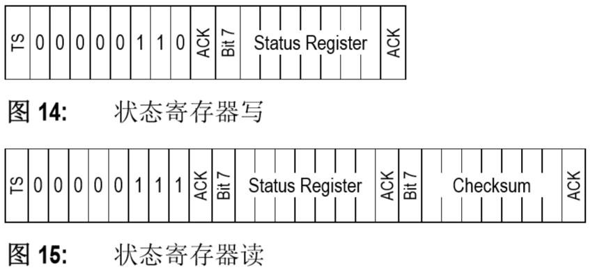
Some advanced functions of SHT1x can be realized by sending instructions to the status register, such as selecting the measurement resolution, reminding the power shortage, using OTP to load or start the heating function, etc. The status register of SHT1x can be read or written. In fact, writing the status register is to configure some features of the device, which is usually completed during initialization. The format of read-write status register is as follows:
/*Read status register*/
static uint8_t ReadStatusRegister(Sht1xObjectType *sht)
{
  uint8_t err=0;
  uint8_t status;
  uint8_t checkSum;

  StartSHT1XOperation(sht);
  err=WriteByteToSht1x(sht,READ_STATUS_REGISTER);
  status=ReadByteFromSht1x(sht,Ack);
  checkSum=ReadByteFromSht1x(sht,noAck);

  if(CheckCRC8ForSHT1x(&status,1,checkSum))
  {
     sht->statusReg=status;
  }
  else
  {
     err+=1;
  }
  return err;
}

/*Write status register*/
static uint8_t WriteStatusRegister(Sht1xObjectType *sht,uint8_t *pValue)
{
  uint8_t err=0;

  StartSHT1XOperation(sht);
  err +=WriteByteToSht1x(sht,WRITE_STATUS_REGISTER);
  err +=WriteByteToSht1x(sht,*pValue);

  err +=ReadStatusRegister(sht);
  return err;
}
3. Use of drivers
We have designed and implemented the SHT1x temperature and humidity sensor driver. Next, we need to verify this driver, so we need to design a simple application based on this driver.
3.1 declare and initialize objects
To use object-based operation, we need to get this object first, so we need to declare a SHT1x temperature and humidity sensor object variable using the SHT1x temperature and humidity sensor object type defined previously. The specific operation format is as follows:
Sht1xObjectType sht1x;
It is declared that this object variable cannot be used immediately. We also need to use the initialization function defined in the driver to initialize this variable. The input parameters required for this initialization function are as follows:
Sht1xObjectType *sht, SHT1X object variable
uint32_t sck, SCK clock frequency
float vdd, operating voltage
SHT1xTempUnitType uint, temperature unit
SHT1xHeaterType heater, enable heater setting or not
SHT1xOTPType otp, add to OTP setting or not
Sht1xresolution type resolution, measurement resolution setting
SHT1xSetBusPin setSckPin, SCK pin operation function
SHT1xSetBusPin setDataPin, DATA pin operation function
SHT1xReadSDABit readSDA, read DATA pin function
Sht1xsdirection, DATA pin direction configuration function
SHT1xDelay delayus, microsecond delay function
Sht1xdelay delays, millisecond delay function
For these parameters, we have defined the object variables. The clock frequency is based on the actual input, in K, and the default is 100k. The working voltage is input according to the actual situation. Temperature unit, heating setting, OTP configuration and resolution configuration are all enumeration, so it's better to choose them according to the actual situation. The main thing is that we need to define several functions and use function pointers as parameters. The types of these functions are as follows:
/* Function pointer defining GPIO pin output operation */
typedef void(*SHT1xSetBusPin)(SHT1xPinValueType value);

/* Read data bus function */
typedef uint8_t (*SHT1xReadSDABit)(void);

/* Data bus direction control function */
typedef void (*SHT1xSDADirection)(SHT1xIODirectionType direction);

/* Microsecond delay function */
typedef  void (*SHT1xDelay)(volatile uint32_t period);
For these functions, we can define them according to the style. The specific operation may be related to the hardware platform used. Chip selection operation function is used for software operation of multiple devices. If hardware chip selection is used, NULL can be passed in. The specific functions are defined as follows:
/*Operate SCK pin, set high and low operation*/
static void OperationSckPin(SHT1xPinValueType value)
{
  HAL_GPIO_WritePin(GPIOB,GPIO_PIN_8,(GPIO_PinState)value);
}

/*Operate DATA pin, set high and low operation*/
static void OperationDataPin(SHT1xPinValueType value)
{
  HAL_GPIO_WritePin(GPIOB,GPIO_PIN_9,(GPIO_PinState)value);
}

/*Read DATA pin*/
uint8_t ReadDataPinBit(void)
{
  return (uint8_t)HAL_GPIO_ReadPin(GPIOB,GPIO_PIN_9);
}

/*Set DATA line to input / output direction mode*/
void SetDataPineDirection(SHT1xIODirectionType direction)
{
  GPIO_InitTypeDef GPIO_InitStruct;

  GPIO_InitStruct.Pin = GPIO_PIN_9;
  if(direction)
  {
    GPIO_InitStruct.Mode = GPIO_MODE_INPUT;
    GPIO_InitStruct.Pull = GPIO_NOPULL;
  }
  else
  {
    GPIO_InitStruct.Mode = GPIO_MODE_OUTPUT_PP;
    GPIO_InitStruct.Speed = GPIO_SPEED_FREQ_HIGH;
  }
  HAL_GPIO_Init(GPIOB, &GPIO_InitStruct);
}
For the delay function, we can use various methods. The STM32 platform and HAL library we used can directly use HAL_Delay() function. Then we can call the initialization function as follows:
SHT1xInitialization(&sht1x,100,3.3,DegreeCentigrade,SHT1xHeaterDisable,SHT1xOTPEbable,SHT1xHighResolution,OperationSckPin,OperationDataPin,ReadDataPinBit,SetDataPineDirection,Delayus,HAL_Delay);
Here we initialize the SHT1x object to a speed of 100k, 3.3V working voltage, adopt the Celsius temperature unit, disable the on-chip heater, load the OTP and use the high resolution.
3.2 operation based on objects
We define the object variable and initialize it with the initialization function. Then we consider manipulating this object to get the data we want. We have got the data in the driver and converted it to the scale value of the conversion value. Next, we use this driver to develop our application example.
Here we design a simple application, using SHT1X temperature and humidity sensor to obtain temperature, humidity and dew point data, the specific implementation is as follows:
/* Get SHT1X data */
void GetSHT1xData(void)
{
   float temperature=0.0;
   float humidity=0.0;
   float dewPoint=0.0;

   GetSht1xMeasureValue(&sht1x);

   temperature=sht1x.temperature;
   humidity=sht1x.humidity;
   dewPoint=sht1x.dewPoint;
}
4. Application Summary
We realize the driving of SHT1X temperature and humidity sensor, and use this driving to develop a simple verification application. The results are consistent with our expectation, which shows that there is no problem with our driver development.
One thing to note when using the driver is that the object has an operation that controls the input and output directions of the DATA bus pins. In general, we write the input and output direction control function of the pin, and pass in the function pointer as a parameter in the initialization function. If the hardware can be configured as open drain output, the input and output direction of the pin can not be controlled separately. NULL is used as the parameter input in the initialization function.
We need to pay attention to the communication rate. The maximum communication rate supported by different working voltage is different, but I can support 1MHz no matter how, so there is no special requirement, and the influence of voltage can not be considered. In our driver, it can support up to 500kHz, mainly considering that the typical speed of SHT1X is only 100k, and there is no high-speed requirement in most applications.
The complete source code can be downloaded from GitHub: https://github.com/foxclever/ExPeriphDriver
Welcome to: