Previous remarks
After a few twists and turns, the next night I came here, it was rained heavily and there was a power failure.
Now everything is back to normal and I'll make up for the records from the previous days.
Today's Content
The digital tube is used to display numbers, and keys are used to control addition and subtraction.
Devices used
1. 51 Single-chip computer (with four keys) (STC15W4K56S4_LQFP64)
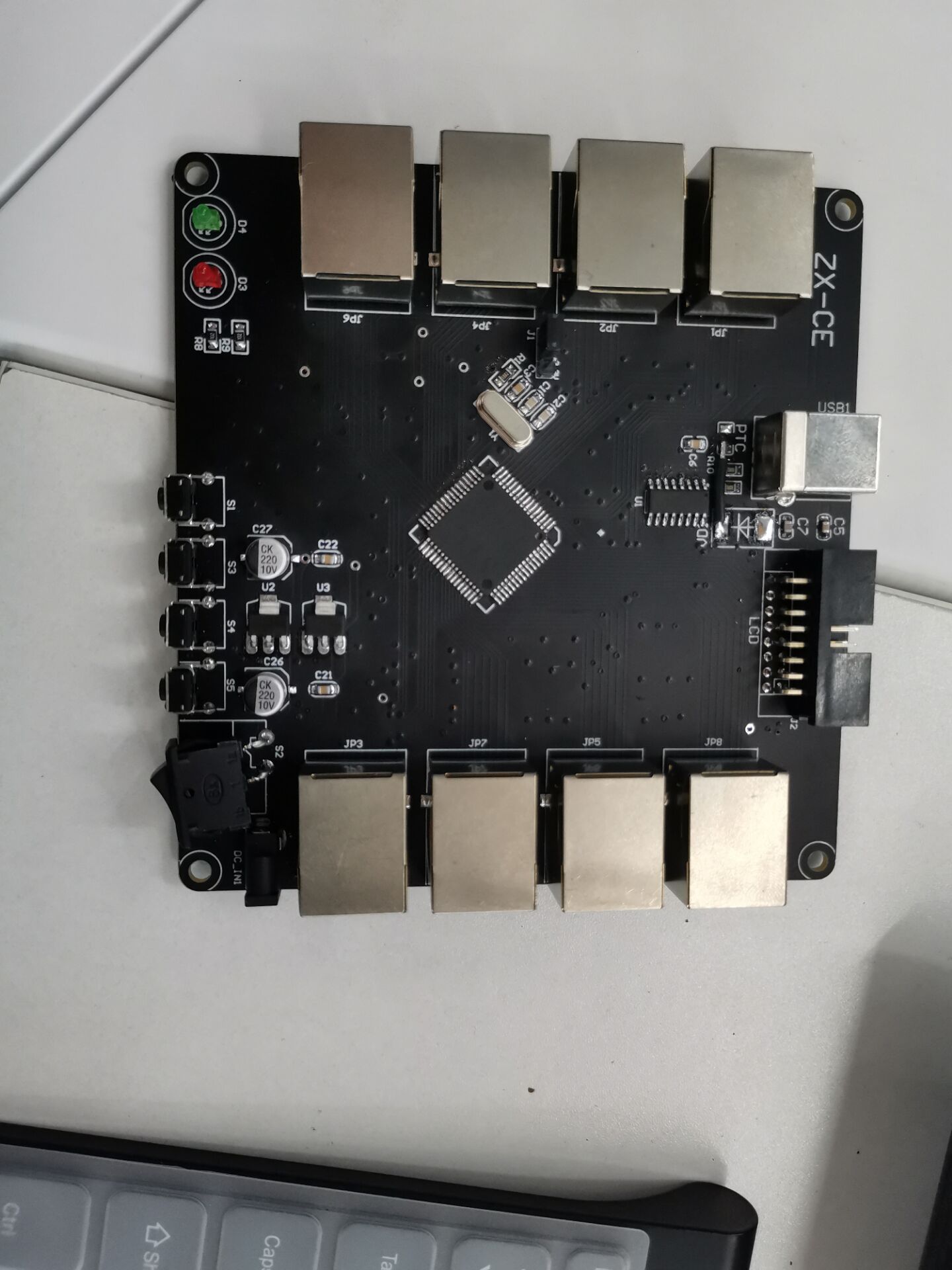
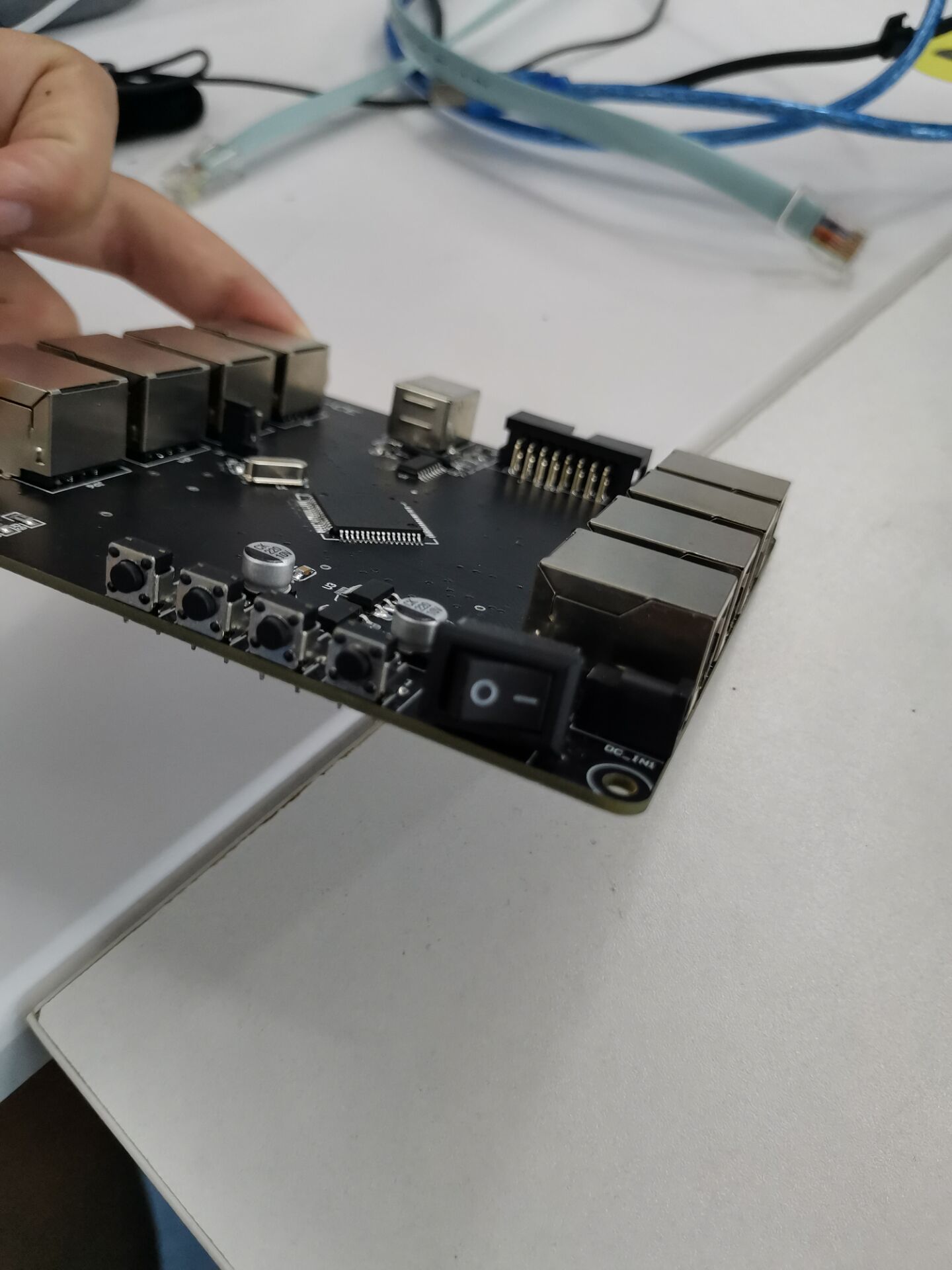
2. 4-digit display digital tube

Required Basics
1. How to Code Key Addition and Subtraction
2. tm1650 Digital Tube Drive Display (LED Drive Private Circuit)
3. I2C communication protocol
TM1650 Digital Tube Driver (1)
The circuit principle diagram

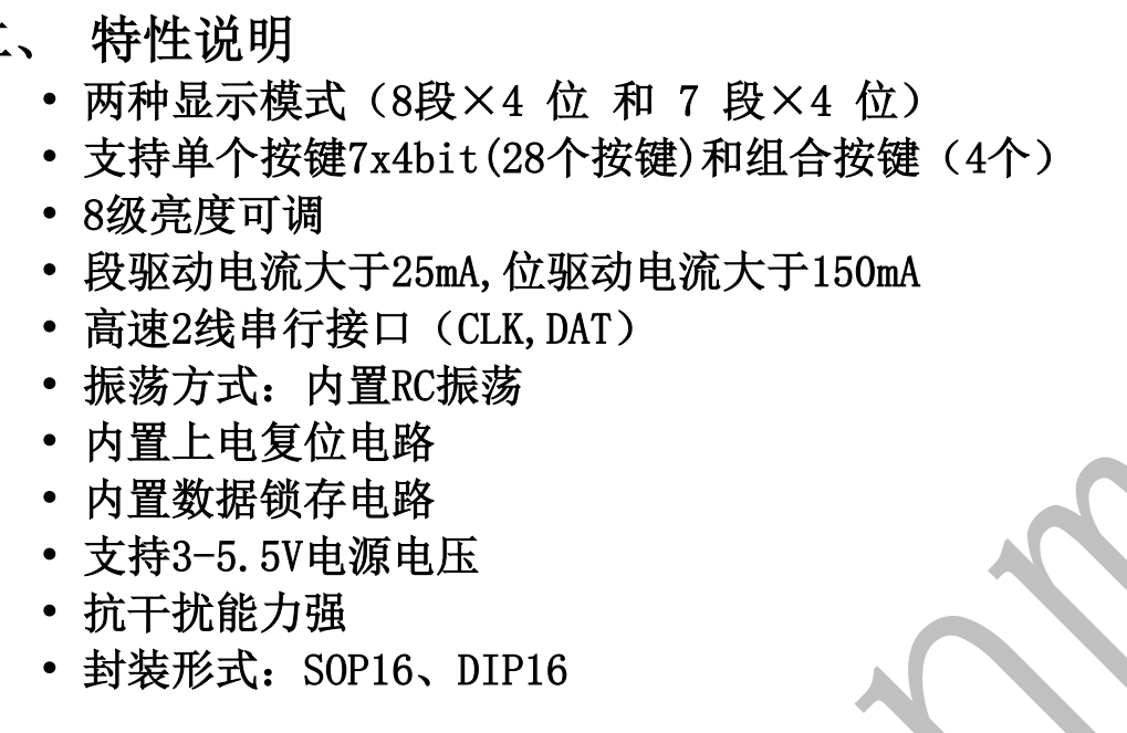
Driver introduction
(The author studies according to the development manual of TM1650, which is also used here to introduce.)
To see the development manual, click here: Stamp here
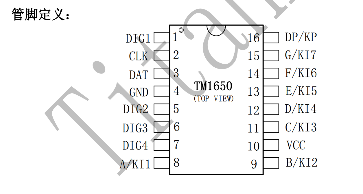
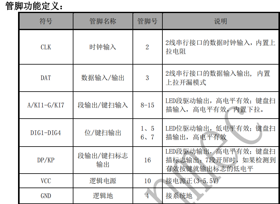

Through the time series format and pin, you can see the I2C communication protocol used by the tm1650 driver.
I2C Protocol
Introduction to I2C Protocol
IIC communication protocol (Inter - - Integrted Circuit) is developed by Phiips Philips. Because of its few pins, simple hardware implementation and high scalability, it does not need UASRT. External transceiver of CAN communication protocol is now widely used for communication among multiple integrated circuits IC (chips) in the system.
Semi-duplex communication
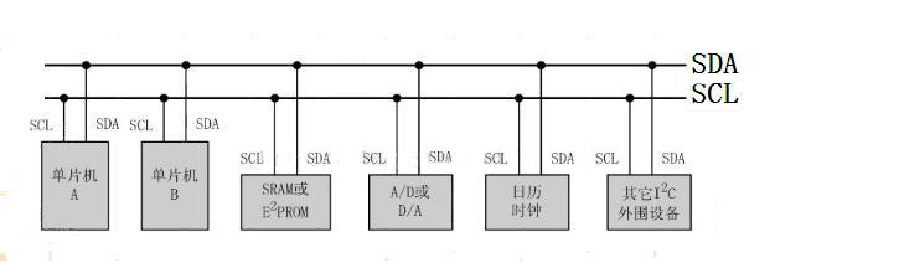
IIC Bus System Architecture

He is a bus that supports multiple devices." Bus refers to the signal line shared by multiple devices. In an IIC communication bus, it can connect multiple IIC communication devices, support multiple communication hosts and multiple communication slaves.
An IIC bus uses only two bus lines, a two-way serial data line (SDA) and a serial clock line (SCL). Data lines are used to represent data, and clock lines are used to synchronize data transmission and reception.
Each device connected to the bus has a separate address that the host can use for direct access to different devices.
IIC Bus Physical Layer Features
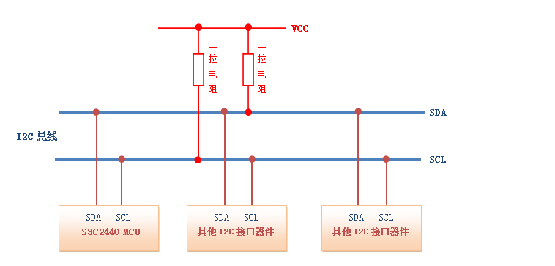
The bus is connected to the power supply through a pull-up resistance. When the IIC device is idle, it outputs a high resistance state, while when all the devices are idle, it outputs a high resistance state, pulling the bus to a high level by pulling up the resistance.
When multiple hosts use the bus simultaneously, arbitration is used to determine which device occupies the bus in order to prevent data conflicts.
There are three transmission modes: standard mode transmission rate is 100 kbit/s, fast mode is 400 kbit/s, high speed mode can reach 3.4M/s, but most IIC devices do not support high speed mode yet.
IIC Bus Protocol Layer
IIC Protocol Layer
The IIC protocol defines the starting and stopping signals for communication, data validity, response, arbitration, clock synchronization, and address broadcasting.
Host writes data to slave
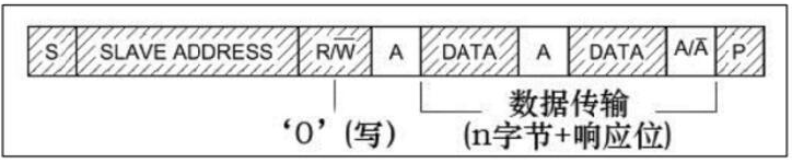

S: Data is transferred from host to slave

P: End of data transfer
SLAVE ADDRESS: slave address
After the start signal is generated, all slave address signals broadcast immediately after the slave start. IIC bus, each device's address is unique. When the host broadcasts the same address as a device's address, the device is selected and the data signal is not ignored by the selected device. According to IIC protocol, this slave address can be 7 or 10 bits.

After the address bit, the transmission direction selection bit is 0: indicating that the direction of data transmission is from the host to the slave, that is, the host to write data from the slave. 1: the opposite. After receiving the transmission direction selection bits from the host, the host or returns an answer (ACK) signal from the opportunity

Or a non-responding (NACK) signal,

The host can continue to send or receive data only after receiving an answer signal.
Host Reads Data to Slave
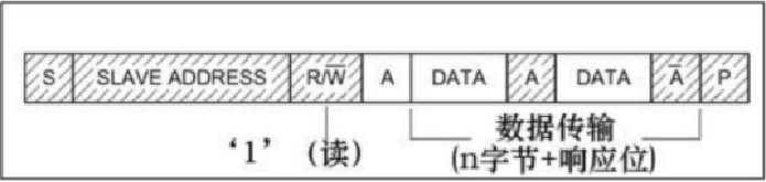
Read data:
Configure Direction Transport Bit to read data direction. After broadcasting the address, after receiving the answer signal, the data (DATA) is returned to the host from the machine, and the packet size is 8 bits. For each number sent from the machine, the host's answer signal (ACK) is waited for. Repeat this process, and N data can be returned with no limit on size. When the host wants to stop receiving data, it returns a non-answering signal (NCAK) to the slave machine and automatically stops data transmission from the machine.
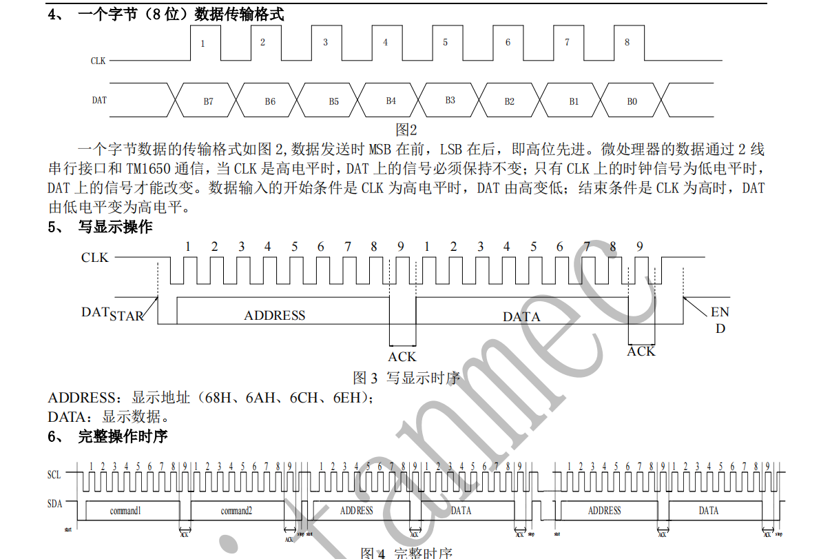
Communication Composite Format
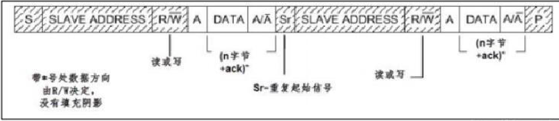
Composite format, which has two start signals (S) during the transmission. During the first transmission, the host passes through SLAVE_ADDRESS sends a "piece of data" when it finds it from the device, which is usually used to represent a register or memory address inside the device; In the second transmission, the content of the address is read or written. That is, the first communication tells the reader to write the address from the machine, and the second communication tells the reader to write the actual content.
Six points of attention for I2C communication
(1) idle state
(2) Start signal
(3) Stop signal
(4) Answer signal
Validity of data
Data transmission
(1) idle signal
The SDA and SCL signal lines of IIC bus are at high level simultaneously, which specifies the idle state of bit bus. At this point, the output-level FETs of each device are in the cut-off state, that is, the bus is released and the level is raised by the pull-up resistors of the two signal lines.
(2) Start signal and (3) Stop signal
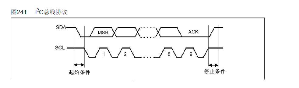
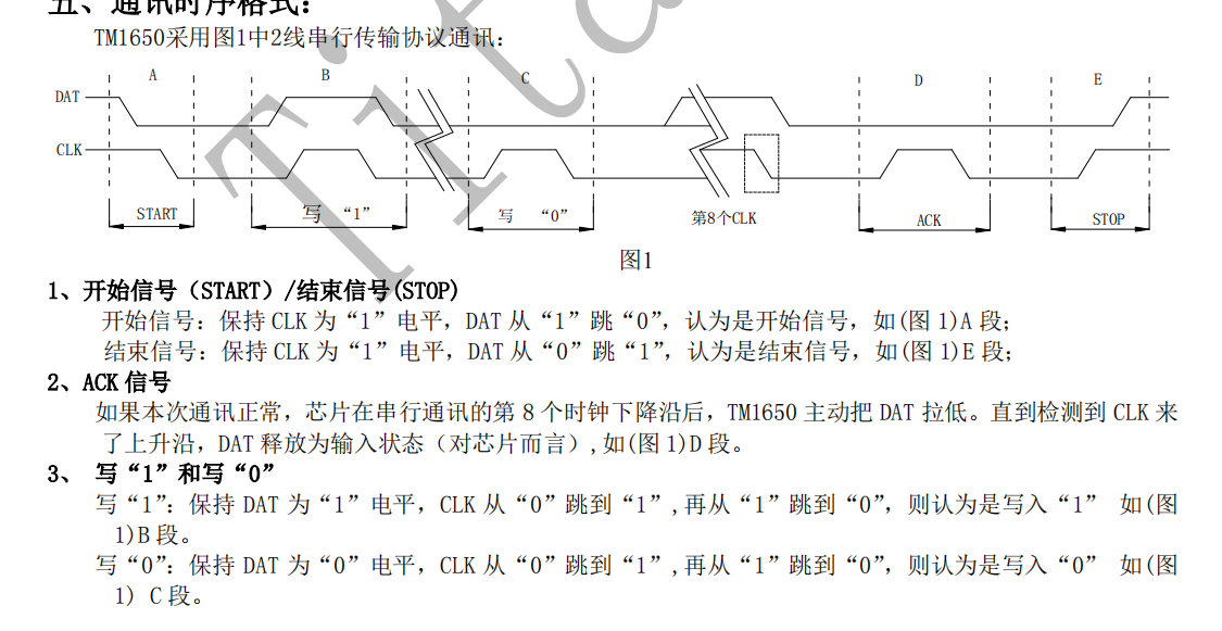
Start signal: SDA has a high to low jump when the SCL is at a high level; The startup signal is a level jump time series signal, not a level signal.
Stop signal: SDA jumps from low to high when SCL is high; Stop signal is also a high level jump time series signal, not a level signal
Start and stop signals are usually generated by the host
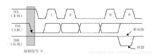
(4) Answer signal
For each byte sent by the transmitter, the data cable is released during the clock pulse 9, and an answer signal is fed back by the receiver. The response signal is at low level and is specified as a valid response bit (ACK for short) to indicate that the receiver has successfully received the byte. Answer signal is high level and is specified as non-response bit (NACK), which generally indicates that the receiver failed to receive the byte.
The requirement for a feedback effective response bit ACK is that the receiver pull down the SDA line during the low level period before the ninth clock pulse and ensure a stable low level during the high level period of the clock.
If the receiver is the master, after it receives the last byte, it sends a NACK signal to notify the controlled transmitter of data transmission and release the SDA cable so that the master receiver sends a stop signal P.
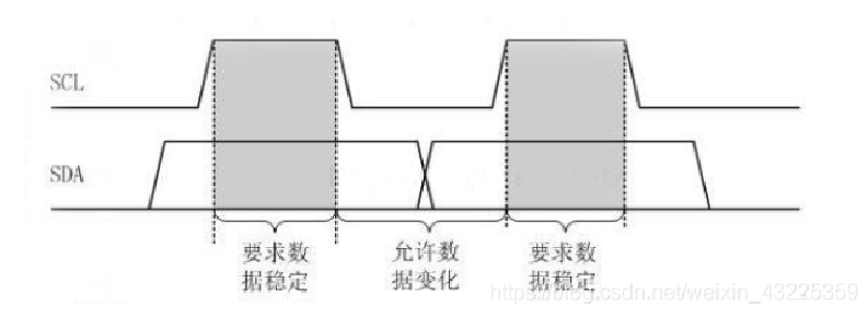
Validity of data
When IIC bus transmits data, the data on the data line must remain stable during the period when the clock signal is at a high level. Only when the signal on the clock line is at a low level, the state of the high or low level on the data line can be allowed to change. The SDA data line transmits one bit of data per clock cycle in the SCL.
That is, the data needs to be prepared before the SCL rises. And must be stable before the downward edge comes
Data transmission
Each data transmitted on the IIC bus has a clock pulse corresponding (or synchronization control), that is, each bit of data is serially transmitted bit by bit on the SDA in conjunction with the SCL serial clock. The transmission of data bits is edge triggered.
TM1650 Digital Tube Driver (2)
TM1650 Time Series Diagram

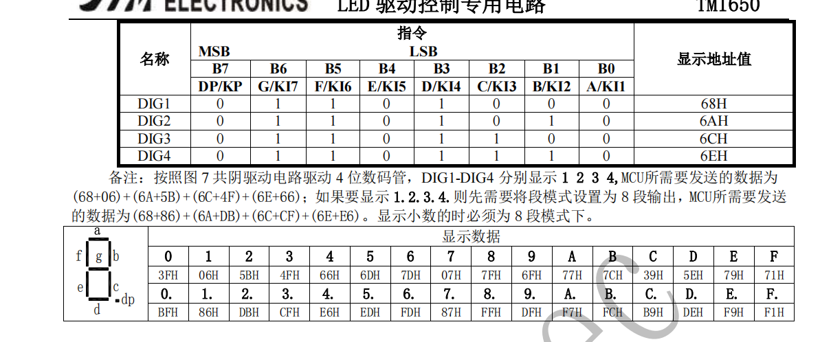
Operation Instruction Set [(System/Key)/Brightness]

Four-digit tube address and display of eight-digit led lights
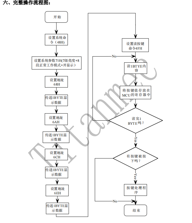
Operation Flowchart
Code
Now that you have finished the necessary knowledge, start coding below!!
header file
#include<STC15F2K60S2.h>
#include<intrins.h>
Define data types
#define uchar unsigned char //Declare definitions of data types
#define uint  unsigned int
Define the digital tube drive pins and keys
sbit CLK = P7^0;    //Clock Line
sbit DIO = P7^1;    //Data line
//Definition statement for TM1650 pin
sbit k1=P6^0;	 //Define P60 as k1
sbit k2=P6^1;	 //Define P61 as k2
sbit k3=P6^2;	 //Define P62 as k3
sbit k4=P6^3;	 //Define P62 as k3
sbit led=P5^5;	 //Define P55 as led
//Definition statement for four keys and led display light
Macro Defines Level Operation of Clock Line and Data Line
#define CLK_H  CLK = 1;
#define CLK_L  CLK = 0;

#define DIO_H  DIO = 1;
#define DIO_L  DIO = 0;
Function declaration
void TM1650_Set(uchar add,uchar dat);//Function declaration
uchar Scan_Key(void);
void Delay_us(uint i);
uchar z=0;
uchar i,j;
uchar flag=0;

uchar code CODE[10] = {0x3f,0x06,0x5b,0x4f,0x66,0x6d,0x7d,0x07,0xff,0x6f};
Delay Functions
/*********************************************************
* Function name: Delay_us
* Functional functions 		   :  Delay function, i=1, approximately 10us
*********************************************************/
void Delay_us(uint i)
{
for(;i>0;i--)
{
_nop_();
_nop_();
_nop_();
_nop_();
_nop_();
}
}
Digital Tube Driven I2C Time Series Start Function
/*********************************************************
* Function name: I2CStart
* Functional functions 		     :  I2C Start Function
*********************************************************/
void I2CStart(void)
{
CLK_H;
DIO_H;
Delay_us(5);
DIO_L;

}
Digital Tube Driven I2C Time Series Response Function
/*****************************************************
* Function name: I2CCask
* Functional functions 		   :  I2C Confirmation Function
*****************************************************/
void I2Cask(void)
{
uchar timeout = 1;
CLK_H;
Delay_us(5);
CLK_L;
while((DIO)&&(timeout<=100))
{
  timeout++;
}
Delay_us(5);
CLK_L;
}
Digital Tube Drive I2C Time Series Stop Function
/*************************************************************
* Function name: I2CStop
* Functional functions 		   :  I2C Stop Function
*************************************************************/
void I2CStop(void)
{
CLK_H;
DIO_L;
Delay_us(5);
DIO_H;
}
Digital Tube Driven I2C Time Series Write Data Function
/*************************************************
* Function name: I2CWrByte
* Functional functions 		 :  Write Section Function
* Input: One byte
* Output 	 :  nothing
************************************************/
void I2CWrByte(uchar oneByte)
{
uchar i;
CLK_L;
Delay_us(1);
for(i=0;i<8;i++)
{
oneByte = oneByte<<1;
DIO = CY;
CLK_L;
Delay_us(5);
CLK_H;
Delay_us(5);
CLK_L;
}
}
Digital tube driver delivers data to specified address
/*******************************************************
* Function name: TM1650_Set
* Functional functions 		   :  Write data function to specified address
* Input: address written by add; Data to be written by dat
* Output 	 :  nothing
*******************************************************/
void TM1650_Set(uchar add,uchar dat)
{
I2CStart();
I2CWrByte(add);
I2Cask();
I2CWrByte(dat);
I2Cask();
I2CStop();
}
Key function
/*******************************************************
* Function name: keypros
* Functional functions 		   :  Key Processing Function to determine if key K1 is pressed
********************************************************/
void keypros()
{


	if(k3==0)
	{
		Delay_us(100);   //Eliminating jitter is generally about 10ms
		if(k3==0)
		{
			flag=1;				//led state reversal
//			led=~led;
		}
		while(!k3);	 //Detect if keys are released
	}
	if(k4==0)
	{
		Delay_us(1000);   //Eliminating jitter is generally about 10ms
		if(k4==0)
		{
			flag=0;				//led state reversal
//			led=~led;
		}
		while(!k4);	 //Detect if keys are released
	}

	if(flag==1)
	{

		if(k1==0)		  //Detect if key K1 is pressed
	     {
		   Delay_us(1000);   //Eliminating jitter is generally about 10ms
		   if(k1==0&&z<99)	     //Determine again if the key is pressed
		   {
//			 led=~led; 				// Led state reversal
			 z++;
		   }
		  TM1650_Set(0x68,CODE[z/10]);
		  TM1650_Set(0x6a,CODE[z%10]);
		  while(!k1);	 //Detect if keys are released
	    }
	  if(k2==0)		  //Detect if key K1 is pressed
	   {
		 Delay_us(1000);   //Eliminating jitter is generally about 10ms
		 if(k2==0&&z>0)	     //Determine again if the key is pressed
		  {
//			led=~led; 				// Led state reversal
			z--;
		  }

		TM1650_Set(0x68,CODE[z/10]);
		TM1650_Set(0x6a,CODE[z%10]);
		 while(!k2);	 //Detect if keys are released
	   }
	}
    if(flag==0)
	{

		TM1650_Set(0x48,0x51);
		TM1650_Set(0x68,CODE[0]);
		TM1650_Set(0x6a,CODE[0]);
    }


}
main function
/*******************************************************
* Function name: main
* Functional functions 		   :  Principal function
* Input: None
* Output 	 :  nothing
********************************************************/


void main()
{

    flag=0;
    while(1)
	{
		keypros();
		}
}
Write at the end
"Actions are better than words"