Single chip microcomputer DS18B20
Readers need to have a preliminary understanding of the DS18B20 data manual before reading.
No more nonsense, go directly to DS180B20 timing
DS18B20 timing
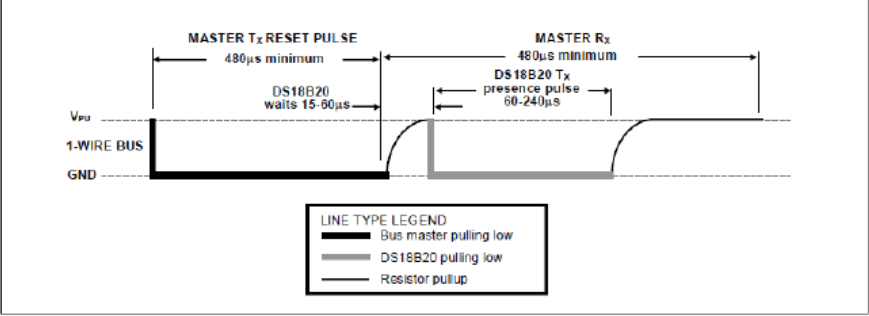
Initialization timing
/**
   * @brief Init_DS18B20()DS18B20 is a function that initializes DS18B20 to determine whether the sensor exists
   *
   * Init_DS18B20()Returns a flag.
   *
   * Init_DS18B20()No parameters
   * @return A flag with success of 1 and failure of 0.
   */
unsigned char Init_DS18B20(){

	bit flag;

	//Pull down the bus
	DQ = 0;
	//500us delay
	delay100us();
	delay100us();
	delay100us();
	delay100us();
	delay100us();
	//delay100us();
	//Pull up bus
	DQ = 1;
	//Continuous 70us delay
	delay_50us(1);
	delay10us();
	delay10us();
	flag = DQ;
	//500us delay
	delay100us();
	delay100us();
	delay100us();
	delay100us();
	delay100us();
	//Return initialization flag
	return flag;
}
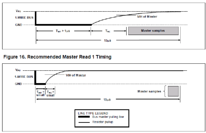
Read timing
/**
   * @brief ReadByte_DS18B20()Yes, DS18B20 is the read timing function, and the sensor is read
   *
   * ReadByte_DS18B20()There are no parameters.
   *
   * @return Returns the value from the sensor
   */
unsigned char ReadByte_DS18B20(){
//The reading cycle takes at least 60 microseconds
unsigned char i,j,bi,byte;

	for(j=8;j>0;j--){
	DQ = 0;
	i++;
	DQ = 1;
	i++;
	i++;
	bi = DQ;
	byte = (byte>>1)|(bi<<7);
	delay10us();
	delay10us();
	delay10us();
	delay10us();
	delay10us();
	delay10us();
	}
return byte;
}
Write timing

/**
   * @brief Write_DS18B20()Yes, DS18B20 is a write timing function and a write operation to the sensor
   *
   * Write_DS18B20()No return value.
   *
   * @param datas Data written to the sensor (command)
   *
   */
void Write_DS18B20(unsigned char datas){
//The write cycle is controlled at 90 minutes
unsigned char j;

//unsigned char i;
	for(j = 0; j<8; j++ )
	{
			DQ = 0;
			DQ = datas&0x01;
		delay_50us(1);
		delay10us();
		delay10us();
		//	i = 6;
			//while(i--);
			DQ = 1;
			datas>>=1;
	}
}
DS18B20 monolithic operation flow
There are three steps:
- DS18B20 initialization
- ROM instruction
- DS18B20 function instruction
ROM instruction
- Search ROM[F0H]
After the system is powered on and initialized, the master device must recognize the ROM codes of all slave devices on the bus, so that the master device can determine the type and quantity of slave devices on the bus. The master device learns the ROM code is a clearing process, so the master device should send the search ROM[F0H] command circularly as needed (the search ROM command follows the data exchange) to determine all the slave devices on the bus.
- Read ROM[33H]
This command can only be used when there is only one slave on the bus. This command enables the master device on the bus to read 64 bits of the slave device without searching the ROM command process ROM encoding. When there is more than one slave on the bus, if the command is sent again, data conflict will be caused when all slaves will respond.
- Match ROM[55H]
The matching ROM command is followed by sending a 64 bit ROM code so that the master device on the bus can match a specific slave device. Only the slave device that exactly matches the 64 bit ROM code will respond to the function command sent by the master device on the bus; Other slaves on the bus will wait for the next reset pulse.
- Skip ROM[CCH]
The master device can use this command to send no ROM encoding command to all slave devices on the bus at the same time.
For example, if the master device sends the skip ROM command to all DS18B20 on the bus and then sends the temperature conversion [44h] command, all devices will execute the temperature conversion at the same time.
It should be noted that when there is only one slave device on the bus, the read temporary register [BEH] command can be followed by the skip ROM command. In this case, the master device can read the data in the slave device without sending 64 bit ROM encoding. When there are multiple slave devices on the bus, if the read temporary register command is sent after skipping the ROM command, all slave devices will start transmitting data at the same time, resulting in data conflict on the bus.
Function instruction
- Temperature conversion [44H]
This command initializes a single temperature conversion. After the temperature conversion, the data of temperature conversion is stored in the temperature register with the length of 2 bytes in the temporary register, and then DS18B20 returns to the idle state of low power consumption. If the device adopts the "parasitic power" power supply mode, after the command is executed 10us (maximum), the main device must forcibly pull up the data cable during temperature conversion. If the device adopts the external power supply mode, the main device can execute the read data timing after the temperature conversion command. If the DS18B20 is in the process of temperature conversion, it will respond to level 0, and when the temperature conversion is completed, it will respond to level 1. In the "parasitic power supply" power supply mode, because the bus is forced to be pulled up during the whole temperature conversion period, there will be no above response.
- Write to temporary register [4EH]
This command causes the master device to write 3 bytes of data to the temporary register of DS18B20. The data of the first byte is written into the TH register (byte 2 of the temporary register), the data of the second byte is written into the TL register (Byte 3), and the data of the third byte is written into the configuration register (Byte 4). All data must be sent first in low order. Before writing all three byte data, the master device must reset the slave device first, otherwise the data will be damaged.
- Temporary register read [BEH]
This command enables the master device to read the value stored in the temporary register. Data is transmitted from the low bit of Byte 0 until the 9th byte (Byte 8 - CRC) is read. If the master device only needs part of the data in the temporary register, it can be terminated by reset in the read data.
- Copy temporary register [48h]
This command copies the values of TH, TL and configuration registers (Byte 2, Byte 3 and Byte 4) in the temporary register to EEPROM. If the device adopts the "parasitic power" power supply mode, the master device must forcibly pull up the 1-Wire bus for more than 10ms within 10us (maximum) after the command is sent.
- Recall EEPROM[B8h]
This command recalls the temperature alarm trigger values (TH and TL) and the data of the configuration register from EEPROM to Byte 2, Byte 3 and byte 4 in the temporary storage register. The master device can execute the read data sequence after the recall EEPROM command. If DS18B20 is recalling EEPROM, it will respond to level 0, and when the recall EEPROM is completed, it will respond to level 1. The recall data operation will be automatically executed once after power on initialization, so there will always be valid data in the temporary register during power on.
/**
   * @brief Transmit_DS18B20()Control DS18B20 for temperature conversion (further modified according to accuracy later) [single chip]
   *
   * Transmit_DS18B20()There are no parameters and return values.
   */
void Transmit_DS18B20(){
	//Temperature conversion
		Init_DS18B20();
		//delay1s();
		delay1ms();
		Write_DS18B20(0xcc);
		Write_DS18B20(0x44);
}
/**
   * @brief TempCom_Read_DS18B20()Obtain the temperature of single chip DS18B20 [single chip]
   *
   * TempCom_Read_DS18B20()There are no parameters and return values.
   */
void TempCom_Read_DS18B20()
{		//Temperature acquisition
		Init_DS18B20();
		delay1ms();
		Write_DS18B20(0xcc);
		Write_DS18B20(0xBE);

}
/**
   * @brief Chang_Mode_DS18B20()Change the conversion accuracy of single chip DS18B20 [single chip]
   *
   * Chang_Mode_DS18B20()There are no parameters and return values.
   */
void Chang_Mode_DS18B20(){
Init_DS18B20();
		delay1ms();
		Write_DS18B20(0xcc);
		Write_DS18B20(0x4E);
		Write_DS18B20(0x16);//TH
		Write_DS18B20(0x00);//TL
	//Write_DS18B20(0x1F);// Accuracy 0.5
	//Write_DS18B20(0x3F);// Accuracy 0.25
	//Write_DS18B20(0x5F);// Accuracy 0.125
		Write_DS18B20(0x7F);//Accuracy 0.0625
}
/**
   * @brief Read_Single_RoCode(unsigned char *romcode)Obtain 64 bit ROM code of single chip DS18B20
   * @param *romcode Is an eight byte romcode array.
   * Read_Single_RoCode(unsigned char *romcode)There are no parameters and return values.
   */
void Read_Single_RoCode(unsigned char *romcode){
Init_DS18B20();
delay1ms();
Write_DS18B20(0x33);
romcode[0]=ReadByte_DS18B20();
romcode[1]=ReadByte_DS18B20();
romcode[2]=ReadByte_DS18B20();
romcode[3]=ReadByte_DS18B20();
romcode[4]=ReadByte_DS18B20();
romcode[5]=ReadByte_DS18B20();
romcode[6]=ReadByte_DS18B20();
romcode[7]=ReadByte_DS18B20();
}
/**
   * @brief Read_Temp_DS18B20()Obtain binary temperature data of single chip DS18B20 [single chip]
   *
   * Read_Temp_DS18B20()There are no parameters.
	 *
	 * @return Returns the sorted binary temperature data
   */
int Read_Temp_DS18B20(){
	//Get the temperature and piece it up into 16 bits
		int temp = 0;
		unsigned char tmh,tml;

		Transmit_DS18B20();
		//delay1s();
	delay1ms();
		TempCom_Read_DS18B20();
		tml = ReadByte_DS18B20();
		tmh = ReadByte_DS18B20();
		temp =tmh;
		temp<<=8;
		temp |=tml;

		return temp;
}