Background introduction
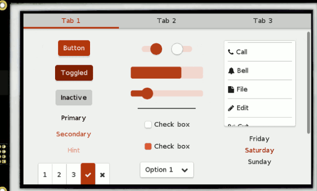
Recently, I'm studying lvgl, an open-source embedded image display framework, which is enough to support some resource deficient MCU to display some professional interfaces, such as the following
And this
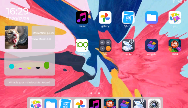
Isn't it cool

Put down Lvgl and don't watch for the time being. Because it is a user interface, most screens can be equipped with touch operation, and there is no need for additional keyboard and mouse. Therefore, today, let's learn to configure the touch screen in my hand.
Resistance screen
Unlike our mobile phones, most embedded devices are equipped with resistive screens because of their high accuracy and low cost.

The most common is my 4-wire resistive screen. It's four wires, x +, X -, y +, Y -.
The principle is as follows:
The four wires are mainly composed of two layers of films plated with ITO coating. One layer has a vertical bus at the left and right edges of the screen, and the other layer has a horizontal bus at the top and bottom of the screen. If you apply voltage on two buses of a thin film, a uniform electric field will be formed on the ITO coating. When the user touches the touch screen, the two films of the touch point will contact, and the voltage value of the contact point can be measured on the other film.
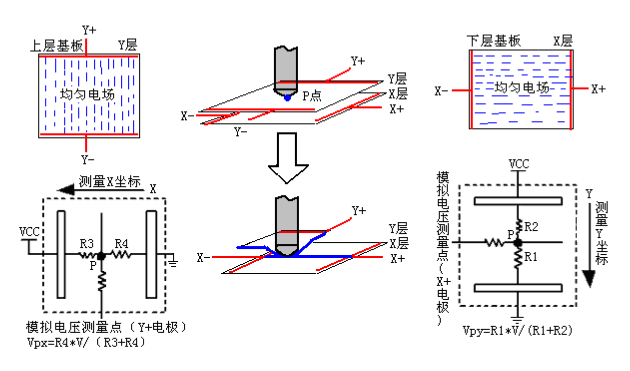
So how to measure the four lines
First step: apply 0V voltage on X - and VCC on X +, then measure the voltage VPX on Y - (or y +) electrode, and then calculate the X coordinate of contact point P.
Step 2: apply a voltage of 0V on Y -, apply VCC on y +, and measure the voltage value VPY on X - (or x +) electrode. Then calculate the Y coordinate of contact point P.
The above two steps can form a measurement cycle and obtain a set of (X,Y) coordinates.
The above is from Introduction to the basic working principle of four wire resistance screen

ADC measurement method (free method)
In principle, I temporarily call it ADC measurement method, because it is obtained by measuring voltage through ADC. Now that the principle is clear, you can start to solve it. Use four gpios to connect the four lines of the screen and program according to the measurement method. This is called requirement transformation code.

critical code
//Get the value of X and y, where x is a pointer to the stored variable
void get_map_x_y(int* x,int* y)
{
	GPIO_InitTypeDef GPIO_InitStruct;

	//Read X value
	//Configure x + as high push-pull and X - as low push-pull
	GPIO_InitStruct.Pin = P_TOUCH_X_JIA;
	GPIO_InitStruct.Mode = GPIO_MODE_OUTPUT;
	GPIO_InitStruct.Pull = GPIO_NOPULL;
	HAL_GPIO_Init(P_TOUCH_PORT, &GPIO_InitStruct);
	HAL_GPIO_WritePin(P_TOUCH_PORT, P_TOUCH_X_JIA, GPIO_PIN_SET);

	GPIO_InitStruct.Pin = P_TOUCH_X_JIAN;
	HAL_GPIO_Init(P_TOUCH_PORT, &GPIO_InitStruct);
	HAL_GPIO_WritePin(P_TOUCH_PORT, P_TOUCH_X_JIAN, GPIO_PIN_RESET);

	//Configure y + as adc mode and Y - as floating input
	hadcy.Instance = ADC;
	hadcy.Init.channel = P_TOUCH_Y_CH;
	hadcy.Init.freq = 1000;
	if (HAL_ADC_Init(&hadcy) != HAL_OK)
	{
		Error_Handler();
	}
	GPIO_InitStruct.Pin = P_TOUCH_Y_JIAN;
	GPIO_InitStruct.Mode = GPIO_MODE_INPUT;
	HAL_GPIO_Init(P_TOUCH_PORT, &GPIO_InitStruct);

	*x=HAL_ADC_GET_INPUT_VOLTAGE(&hadcy);
	HAL_GPIO_WritePin(P_TOUCH_PORT, P_TOUCH_X_JIA, GPIO_PIN_RESET);
	HAL_GPIO_WritePin(P_TOUCH_PORT, P_TOUCH_X_JIAN, GPIO_PIN_RESET);

	//Read Y value
	//Configure y + as high push-pull and Y - as low push-pull
	GPIO_InitStruct.Pin = P_TOUCH_Y_JIA;
	GPIO_InitStruct.Mode = GPIO_MODE_OUTPUT;
	GPIO_InitStruct.Pull = GPIO_NOPULL;
	HAL_GPIO_Init(P_TOUCH_PORT, &GPIO_InitStruct);
	HAL_GPIO_WritePin(P_TOUCH_PORT, P_TOUCH_Y_JIA, GPIO_PIN_SET);

	GPIO_InitStruct.Pin = P_TOUCH_Y_JIAN;
	HAL_GPIO_Init(P_TOUCH_PORT, &GPIO_InitStruct);
	HAL_GPIO_WritePin(P_TOUCH_PORT, P_TOUCH_Y_JIAN, GPIO_PIN_RESET);

	//Configure x + as adc mode and X - as floating input
	hadcx.Instance = ADC;
	hadcx.Init.channel = P_TOUCH_X_CH;
	hadcx.Init.freq = 1000;

	if (HAL_ADC_Init(&hadcx) != HAL_OK)
	{
		Error_Handler();
	}

	GPIO_InitStruct.Pin = P_TOUCH_X_JIAN;
	GPIO_InitStruct.Mode = GPIO_MODE_INPUT;
	HAL_GPIO_Init(P_TOUCH_PORT, &GPIO_InitStruct);

	*y=HAL_ADC_GET_INPUT_VOLTAGE(&hadcx);
	HAL_GPIO_WritePin(P_TOUCH_PORT, P_TOUCH_Y_JIA, GPIO_PIN_RESET);
	HAL_GPIO_WritePin(P_TOUCH_PORT, P_TOUCH_Y_JIAN, GPIO_PIN_RESET);
}
The operation is completely translated according to the schematic diagram. Here, we need to pay attention to that the measurement points X + and Y + should be converted in ADC mode and output mode. Therefore, we should choose the pin that supports both GPIO and ADC conversion. Otherwise, the value cannot be measured.
However, I studied this method for 5 hours, and then found that the voltage measured by the X coordinate was changing on the whole screen. Then I carefully found that there was an ADC chip on the board and the cable had been connected. Therefore, I suspect that this voltage change has something to do with the external chip, so I gave up this practice.
However, this approach is entirely feasible. And there is no need for additional chips. In other words, this practice is free.

ADS7846
The chip on the board is ads7846, which is a very mainstream resistance screen driver chip. It converts the measurement of 4-wire resistance into data reading of SPI bus, and provides interrupt and docking with MCU, which is called a 6.
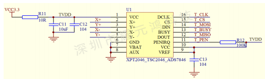
Six wires are provided
| Pin | explain |
|---|---|
| CLK | SPI clock |
| CS | Film selection |
| MOSI | Master output slave input |
| MISO | Host input and slave output |
| BUSY | Busy signal |
| PEN | Interrupt signal |
Here we use GPIO simulation.
GPIO initialization
static void TOUCH_GPIO_Init(void)
{

	GPIO_InitTypeDef GPIO_InitStruct;

	__HAL_RCC_GPIO_CLK_ENABLE();

	GPIO_InitStruct.Pin = TDIN;
	GPIO_InitStruct.Mode = GPIO_MODE_OUTPUT;
	GPIO_InitStruct.Pull = GPIO_NOPULL;
	HAL_GPIO_Init(P_TOUCH_PORT, &GPIO_InitStruct);
	HAL_GPIO_WritePin(P_TOUCH_PORT, TDIN, GPIO_PIN_RESET);

	GPIO_InitStruct.Pin = TCLK;
	HAL_GPIO_Init(P_TOUCH_PORT, &GPIO_InitStruct);
	HAL_GPIO_WritePin(P_TOUCH_PORT, TCLK, GPIO_PIN_RESET);

	GPIO_InitStruct.Pin = TCS;
	HAL_GPIO_Init(P_TOUCH_PORT, &GPIO_InitStruct);
	HAL_GPIO_WritePin(P_TOUCH_PORT, TCS, GPIO_PIN_RESET);

	GPIO_InitStruct.Pin = DOUT;
	GPIO_InitStruct.Mode = GPIO_MODE_INPUT;
	GPIO_InitStruct.Pull = GPIO_PULLUP;
	HAL_GPIO_Init(P_TOUCH_PORT, &GPIO_InitStruct);

	GPIO_InitStruct.Pin = PEN;
	GPIO_InitStruct.Mode = GPIO_MODE_IT_FALLING;
	GPIO_InitStruct.Pull = GPIO_PULLUP;
	HAL_GPIO_Init(P_TOUCH_PORT, &GPIO_InitStruct);

	HAL_NVIC_SetPriority(GPIOA_IRQn, 0);
	HAL_NVIC_EnableIRQ(GPIOA_IRQn);


}
Note here that to open the interrupt, the PEN pin is at a low level when there is a touch. When the hand is taken away, it is at a high level. Therefore, if you want to read continuously, you should constantly judge the battery of PEN pin.
BUSY signal can also be used. It can be initialized to read in mode.
Core function, reading coordinates
#define CMD_ RDX 0X90 / / 0b10010000, i.e. read X coordinates in differential mode
#define CMD_RDY 	 0xd0 / / 0b11010000, i.e. read Y coordinates in differential mode

//Read X,Y values once
//The read X and Y coordinate values must be greater than 100
//1 is returned for success and 0 is returned for failure
//The reading is limited to 100 ~ 3800
const float y_sin=0.1348;
const float x_sin=0.1739;

int get_map_x_y(int* X,int* Y)
{
	int px=0,py=0;
	start_spi();//Start SPI

	WriteByteADS(CMD_RDX);
	//The maximum conversion time of ADS7846 is 6us
	TCLK_SET(1);
	delay_us(3);
	TCLK_SET(0);
	delay_us(3);

	px=ReadWordADS();
	WriteByteADS(CMD_RDY);
	//The maximum conversion time of ADS7846 is 6us
	TCLK_SET(1);
	delay_us(3);
	TCLK_SET(0);
	delay_us(3);

	py=ReadWordADS();//Read Y-axis coordinates
	TCS_SET(1);
	if((px>100)&&(py>100)&&(px<3800)&&(py<3800))
	{
		int abs_px,abs_py;
		abs_px=px-100;
		abs_py=py-100;
		*X=x_sin*abs_px;
		*Y=y_sin*abs_py;
		return 1;//Reading successful (range limit)
	}
	else
	{
		return 0;							 //Reading failed
	}
}
I first tried the coordinates of the four corners, and then estimated the units of the x-axis and y-axis, that is, the coordinates read. How many pixels does one unit represent. The following two values are obtained.
const float y_sin=0.1348;
const float x_sin=0.1739;
Then you can remove the starting value according to the read value and multiply it by the coefficient just now to get the specific coordinates of my 320 * 240 screen.
abs_px=px-100;
abs_py=py-100;
X=x_sinabs_px;
Y=y_sinabs_py;

Drawing board
In the previous 16 articles, the drive line has been completed, Single chip microcomputer HLK-W801 parallel port drive ST7789
Then combined with today's touch screen, we can make a drawing board.

Interrupt judgment, here is only a flag bit, which will be triggered if there is a touch operation.
 void HAL_GPIO_EXTI_Callback(GPIO_TypeDef *GPIOx, uint32_t GPIO_Pin)
{
	if ((GPIOx == P_TOUCH_PORT) && (GPIO_Pin == PEN))
	{
		key_flag = 1;
	}
}
Then, in the main function, continue to read and draw points.
	while (1)
	{
		if (key_flag == 1)
		{
			HAL_Delay(20);
			while(HAL_GPIO_ReadPin(P_TOUCH_PORT, PEN) == GPIO_PIN_RESET)
			{
				int pos_x=0, pos_y=0;
				get_map_x_y(&pos_x,&pos_y);
				LCD_DrawPoint(320-pos_x,pos_y, 0xf000);
				HAL_Delay(5);
			}
			key_flag = 0;
		}
	}
In HAL_Delay has different rendering effects under different conditions.
HAL_Delay(20)
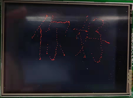
HAL_Delay(5)
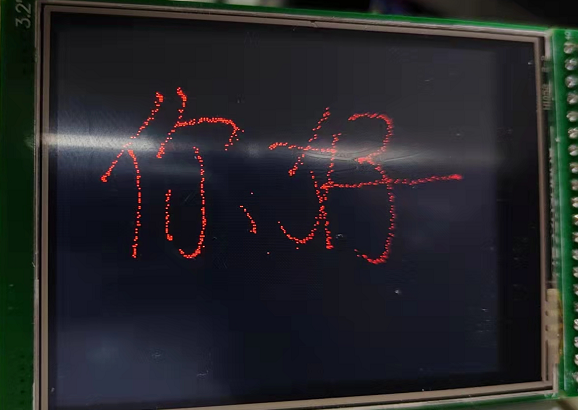
Remove delay
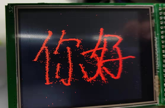
It can be seen that when there is a delay, the coordinates are relatively clean. When there is no delay, there will be many drift points when writing and starting. This drift effect is like the effect of sand painting.
Concluding remarks
This article is just to learn lvgl and make a technical reserve as the input method of lvgl. I have mastered the two methods of resistance measurement.

Yesterday was women's day. Girls disliked the name and looked earthy. Later, it was called goddess day. In fact, this festival was founded by women workers in order to strive for equal welfare. Its full name is "United Nations women's rights and international day of peace". My colleagues said that in fact, married women's husbands should also be given half a day, which can better give women a holiday. I think it makes sense.