Note: the model of this single chip microcomputer is STC15F2K60S2
principle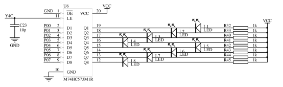
As shown in the figure, light emitting diodes L1-L8 are in common positive connection, and VCC is the positive pole of power supply, with high level.
It is known that the LED is on in the forward direction and off in the reverse direction. In order to make the diode light, Q1-Q8 should be low. The controllable pin is P00-P07, so input P00-P07 as low level. In order for P0 to affect Q1-Q8, make latch M74HC573M1R on, that is, make pin LE high. In addition, pin LE is connected with Y4C, so Y4C is also high.
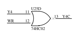
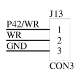
Y4C is connected to a NOR gate, and the inputs of the NOR gate are Y4 and wr. Because WR has been connected with GND with jumper cap and GND is grounded, WR is 0 (low level).
According to the NOR gate logic table:
Y4	      WR	   Y4C
0	       0	     1
0          1   	     0
1	       0	     0
1	       1	     0
Therefore, when Y4C is 0, Y4 is 1; When Y4C is 1, Y4 is 0
Therefore, to make Y4C high level, Y4 must be low level, that is, Y4 is 0
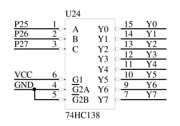
Y4 is controlled by the inputs A, B and C of the 74HC138 bit decoder. Taking C, B and A as the logical order, CBA forms A binary number to select Y0-Y7. The selected one is the low level.
Therefore, to make Y4 low, CBA should be 100
In addition, since port P0 is multiplexed, it means that other devices should also be controlled. Therefore, if LE is kept high, the LED will be affected when controlling other devices. Therefore, after the latch is turned on, its state should be cut off and saved.
Collation logic:
Light up LED:
Q1—Q8 Low level -> P00-P07 Low level -> Turn on the latch, LE High level ->
Y4C High level -> Or not, Y4 Low level -> Decoder, CBA The combination is 100 ->
Latch status,Disconnect the latch, LE Low level, Y4C Low level ->
Or not, Y4 High level -> Decoder, CBA The combination is 000.(Not 100)

Similarly, extinguish LED:
Q1—Q8 High level -> P00-P07 High level -> Turn on the latch, LE High level ->
Y4C High level -> Or not, Y4 Low level -> Decoder, CBA The combination is 100 ->
Latch status,Disconnect the latch, LE Low level, Y4C Low level ->
Or not, Y4 High level -> Decoder, CBA The combination is 000.(Not 100)
code
Source: official information of Blue Bridge Cup.
#include "reg52.h"
// #include "absacc.h"
// Turn off peripherals
void Cls_Peripheral(void)
{ // IO mode (J13-2 and J13-3 connected)
  P0 = 0xFF;
  P2 = P2 & 0x1F | 0x80;			// Clear P27~P25 and reposition Y4C
  P2 &= 0x1F;						// P27~P25 reset
  P0 = 0;
  P2 = P2 & 0x1F | 0xA0;			// Clear P27~P25 and reposition Y5C
  P2 &= 0x1F;						// P27~P25 reset
//XBYTE[0x8000] = 0xFF; 				//  MM mode (J13-2 and J13-1 connected)
//XBYTE[0xA000] = 0;
}
// LED display
void Led_Disp(unsigned char ucLed)
{ // IO mode (J13-2 and J13-3 connected)
  P0 = ~ucLed;                      //unsigned char
  P2 = P2 & 0x1F | 0x80;			// Clear P27~P25 and reposition Y4C
  P2 &= 0x1F;						// P27~P25 reset
//XBYTE[0x8000] = ~ucLed; 			//  MM mode (J13-2 and J13-1 connected)
}
// Delay function (minimum approx 1ms@12MHz )
void Delay(unsigned int num)
{
  unsigned int i;
  while(num--)
    for(i=0; i<628; i++);
}
// Main function
void main(void)
{
  unsigned char i, j;

  Cls_Peripheral();

  while(1)
  { // 4 brightness levels
    for(i=0; i<4; i++)
      for(j=0; j<100; j++)
      {
        Led_Disp(0xff);
        Delay(i+1);
        Led_Disp(0);
        Delay(4-i);
      }
  }
}
Section 1: turn off peripherals.
Because the default P port of C51 single chip microcomputer is high level, the LED and buzzer will work before the program runs. See this for the specific principle @My head is by no means kneaded by dough -- a preliminary study on turning off peripherals in Blue Bridge Cup single chip microcomputer competition series 1.
The code goes straight here:
// Turn off peripherals
void Cls_Peripheral(void)
{ // IO mode (J13-2 and J13-3 connected)
  P0 = 0xFF;
  P2 = P2 & 0x1F | 0x80;			// Clear P27~P25 and reposition Y4C
  P2 &= 0x1F;						// P27~P25 reset
  P0 = 0;
  P2 = P2 & 0x1F | 0xA0;			// Clear P27~P25 and reposition Y5C
  P2 &= 0x1F;						// P27~P25 reset
//XBYTE[0x8000] = 0xFF; 				//  MM mode (J13-2 and J13-1 connected)
//XBYTE[0xA000] = 0;
}
(Note: I still don't understand this IO mode. I'll fill it in after I understand it. I'll put a reference blog first—— liu_endong -- 51 Single Chip Microcomputer -- IO port working mode and configuration)
Section 2: LED display
// LED display
void Led_Disp(unsigned char ucLed)
{ // IO mode (J13-2 and J13-3 connected)
  P0 = ~ucLed;                      //unsigned char
  P2 = P2 & 0x1F | 0x80;			// Clear P27~P25 and reposition Y4C
  P2 &= 0x1F;						// P27~P25 reset
//XBYTE[0x8000] = ~ucLed; 			//  MM mode (J13-2 and J13-1 connected)
}
First set port P0, select the coded ucled of the lamp to be lit, then select Y4 on latch, and then latch after the LED is lit.
Section 3: delay function
// Delay function (minimum approx 1ms@12MHz )
void Delay(unsigned int num)
{
  unsigned int i;
  while(num--)
    for(i=0; i<628; i++);
}
Needless to say, I should understand everything.
Paragraph 4: main function
void main(void)
{
  unsigned char i, j; //Set unsigned char type parameters i, j

  Cls_Peripheral();   //Turn off peripherals

  while(1)            //loop
  { // 4 brightness levels
    for(i=0; i<4; i++)
      for(j=0; j<100; j++)
      {
        Led_Disp(0xff);//1111, 1111, all out
        Delay(i+1);    //Set delay time
        Led_Disp(0);   //0000 0000 all on
        Delay(4-i);    //
      }
  }
}
In fact, the breathing lamp is to light the led lamp with different brightness. The key is how to light the led lamp with different brightness, that is, to change the brightness of the led lamp. The simple method is to change the proportion of led lighting time within the time range that can not be observed by the naked eye, so as to form the visual effect of different brightness.
// 4 brightness levels
for(i=0; i<4; i++)
      for(j=0; j<100; j++)
      {
        Led_Disp(0xff);//1111, 1111, all out
        Delay(i+1);    //Set delay time
        Led_Disp(0);   //0000 0000 all on
        Delay(4-i);    //
      }
Two cycles, the first cycle and the Delay function are used to set the on and off time, so as to set the brightness level of the lamp. The second cycle sets the running time of each brightness level.
The content of the second cycle is to divide the on and off time into four parts, and adjust the brightness of the lamp according to different combinations.
Racing lamp code
#include<reg51.h>
#include<intrins.h> 	// The library has left and right shift functions
#define  led P0

typedef unsigned int u16;
typedef unsigned char u8;


void delay(u16 i)
{
	while(i--);
}

void main()	//Mode 1
{
	u8 i;
	led = ~0x01;//Reverse 0000 0001
	delay(50000);
	while(1)
	{
		for(i=0; i<8; i++)//Moving left causes the LED to light from left to right
		{
			led = ~(0x01<<i);  //0000 0001
			delay(50000);
		}

		for(i=0; i<8; i++)//Moving right causes the LED to light from right to left
		{
			led = ~(0x80>>i);  //1000 0000
			delay(50000);
		}
	}
}

/***************Mode 2*****************************/
 /*
void main()
{
	u8 i;
	led = ~0x01;
	delay(50000);
	while(1)
	{
		for(i=0; i<7; i++)		 //for Template: for(1 assignment / operation; 2 conditions to be met; 3 operation)
		{						 			 //	{Statement;}
			led=_crol_(led,1);
			delay(50000);
		}						 	//Start with 1, then 2, then 3, then 2... Until condition 2 is not met

		for(i=0; i<7; i++)
		{
			led=_cror_(led,1);
			delay(50000);
		}

	}
}  */