1. Hardware preparation: Warship development board, PS2 handle receiver, PS2 handle, connection cable
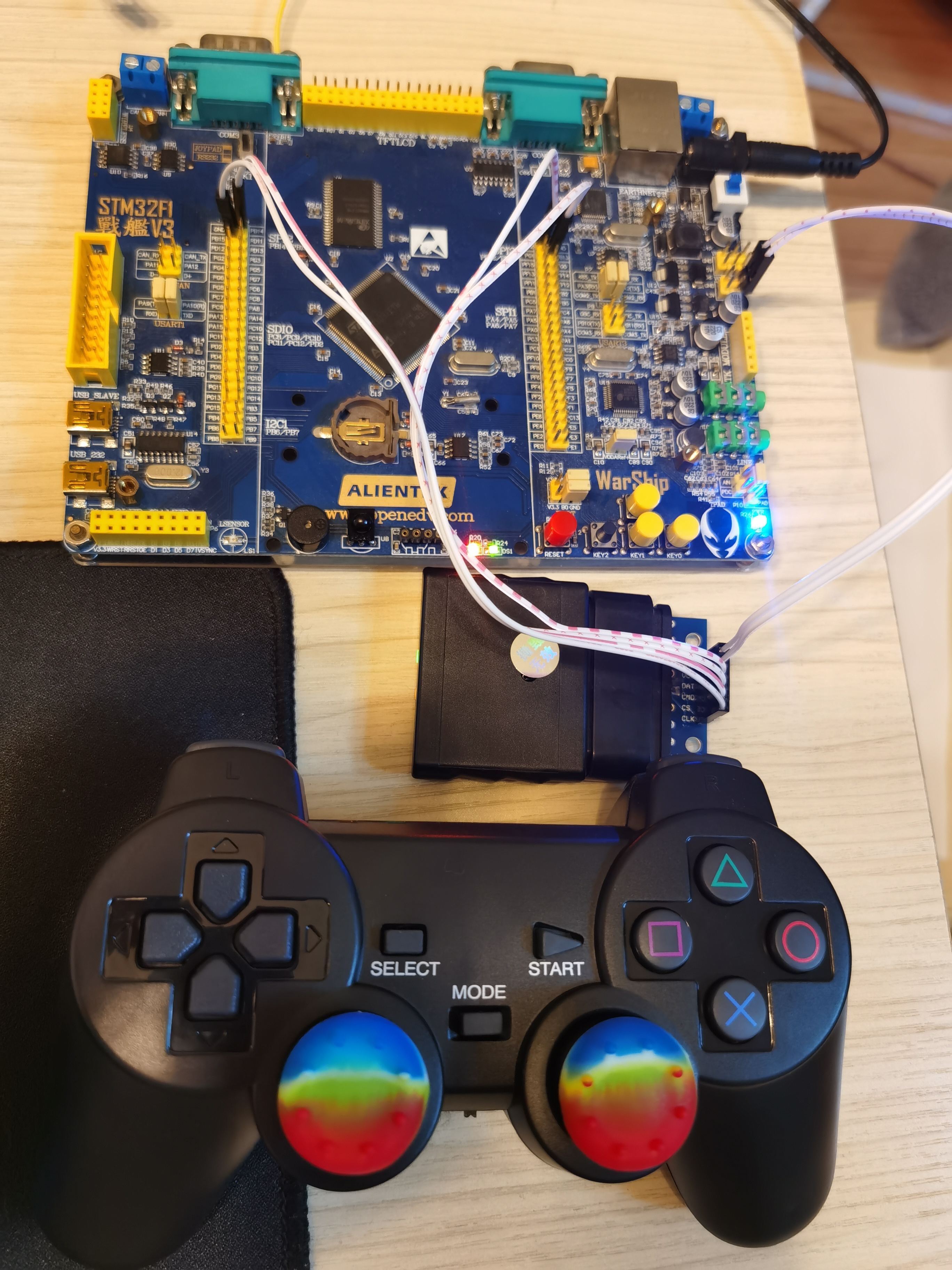
2. Hardware connection:
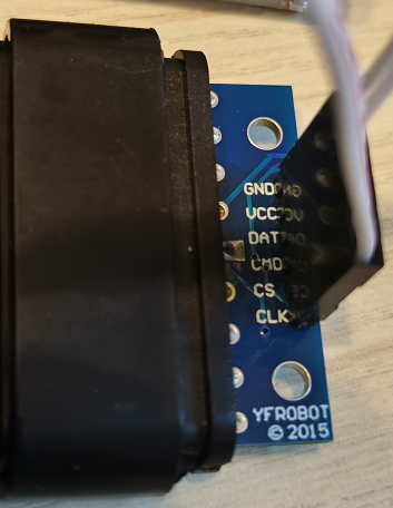
The PS2 handle receiver has six pins and connects to the IO port of the single-chip computer as follows:
| Receiver signal | Single-chip IO |
|---|---|
| GND | GND |
| VCC | 3.3V |
| DI/DAT | PB12 |
| DO/CMD | PB13 |
| CS | PB14 |
| CLK | PB15 |
3. Introduction to PS2 Communication
The communication sequence is as follows, which feels like the SPI and is also four-line
DI and DO are a pair of 8 bit serial data transmitted at the same time. CS is required for low level and CLK is changed from high to low.
DO is the signal sent to the receiver by the single-chip computer.
DI is the signal sent by the receiver to the single-chip computer.
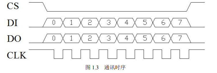
First point: CS is low when data is output or input, so we first pull the CS up and down when data is transmitted, then the data is transmitted, and then the CS is raised after transmission is completed.
Second point: DI(Data Input) and DO(Data Output) are completed at the same time, indicating that this is full duplex communication. Serial port is full duplex communication. IIC is a half-duplex communication.
Third, when the clock goes up and down, DI and DO data cross, that is, data exchange (data only 0 and 1), at this time we can not read and write data, because the data is not stable, the data we read is not accurate. When the clock goes down, the data is stable and we start reading and writing data at this time.
Fourth point: Since it is from 0 to 7, you know that there are 8 bits of data, and they are read and written from low to high. We can put the data in an array. A clock performs a data bit (also known as bit 0 or 1) transmission.
Clock frequency 250KHZ (4us), data instability can increase frequency appropriately.
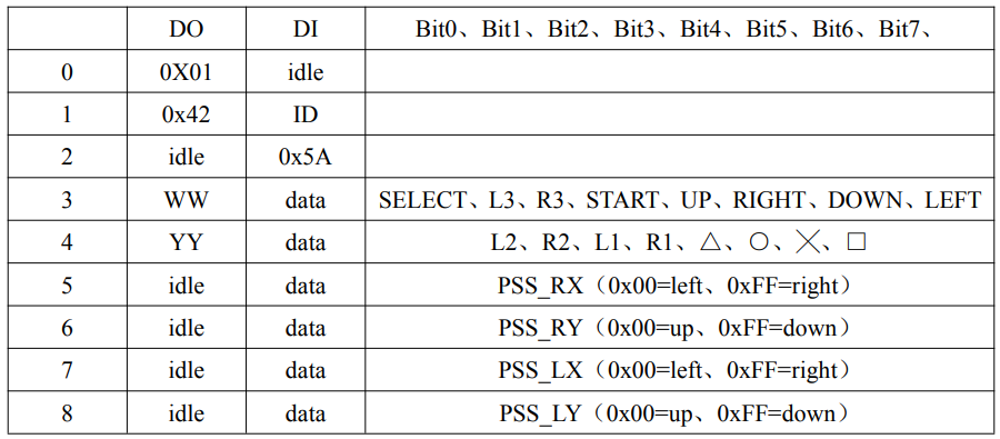
When the single chip computer sends 0x01, the receiver will reply with its ID "0X41 for green light mode", "0x73 for red light mode"; While the ID is sent by the handle, the single-chip computer will send 0X42, the handle will send 0X5A, high-speed single-chip computer data.
Idle in the table above indicates that the data line is idle and there is no data transfer for that data line.
So Data[0], Data[1], Data[2] can't be used to store keys for the PS2 rocker
Values used by Data[3], Data[4] to store keys
Data[5], Data[6], Data[7], Data[8] The analog amount used to store the rocker
When there is a key, the corresponding bit is 0, the other bit is 1
For example, when SELECT is pressed, Data[3]=1111 1110B
When L3 is pressed, Data[3]=1111 1101B
When R3 is pressed, Data[3]=1111 1011B
When START is pressed, Data[3]=1111 0111B
When UP is pressed, Data[3]=1110 1111B
When RIGHT is pressed, Data[3]=1101 1111B
When DOWN is pressed, Data[3]=1011 1111B
When LEFT is pressed, Data[3]=0111 1111B
The handle has two modes, red light mode (handle lights up red + green) and green light mode (handle only lights up green), which can be switched by pressing the MODE key.
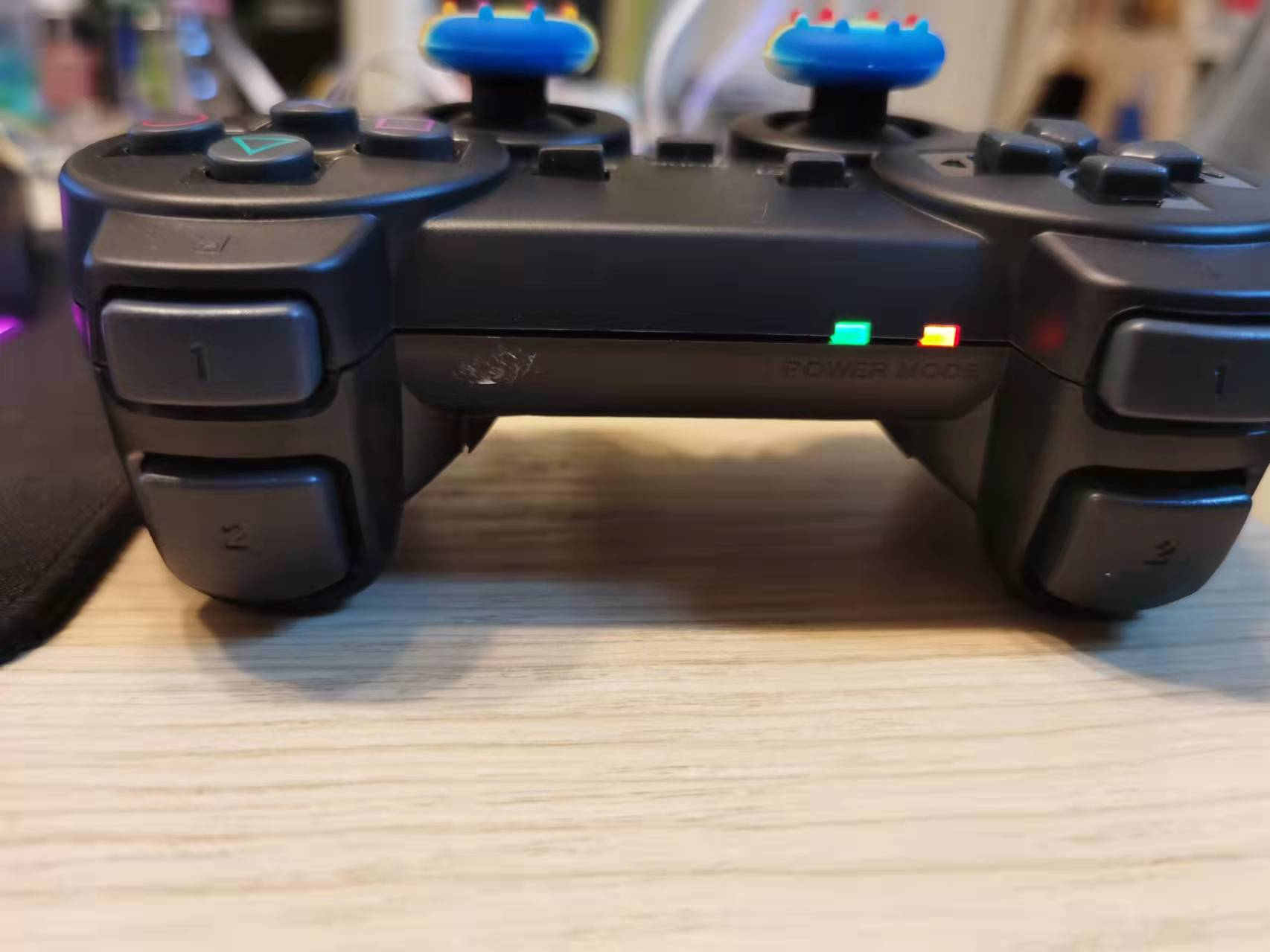
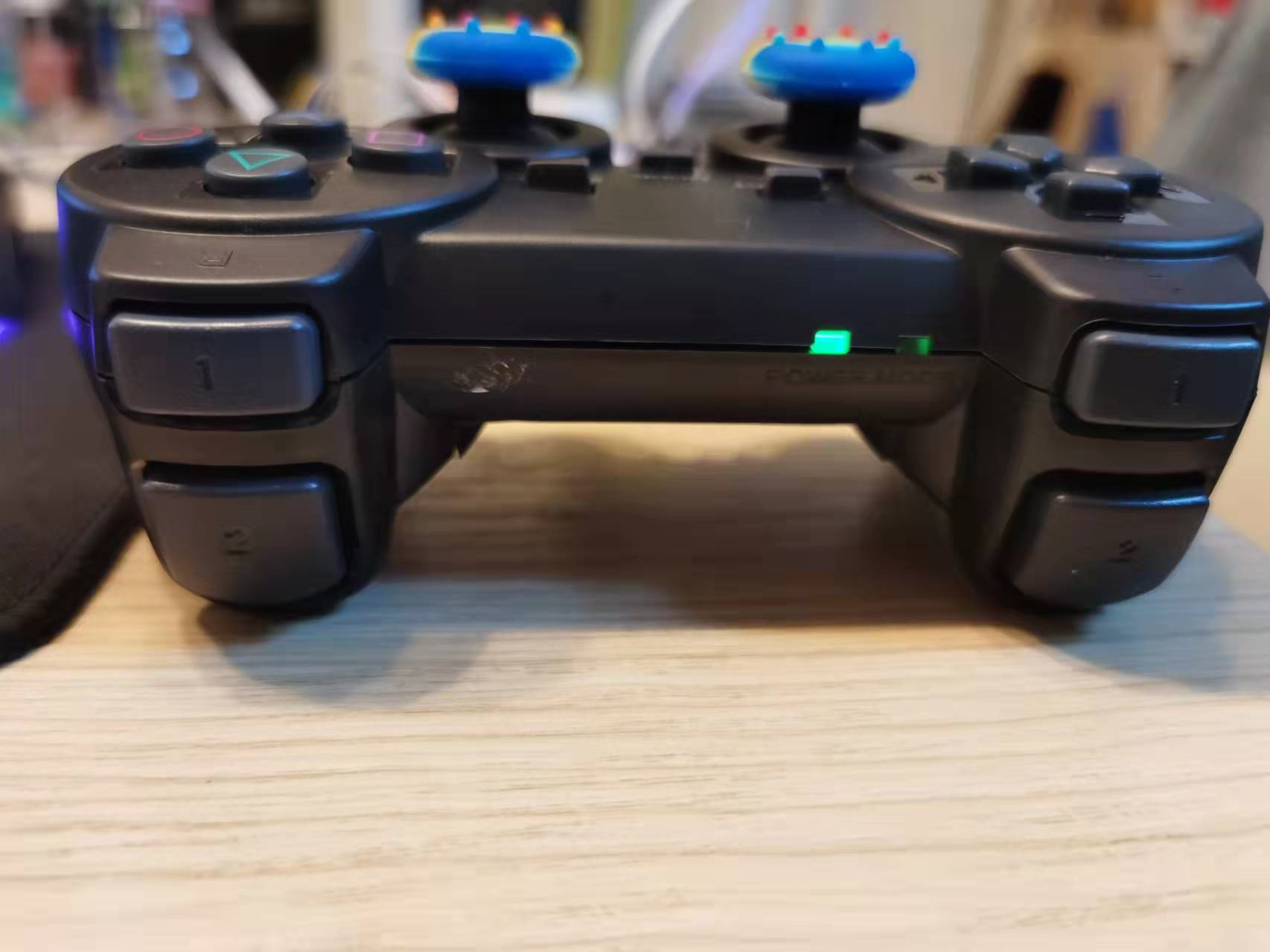
Red light mode:
1. The key L3/R3 is pressed effectively
2. Push the left and right rockers to output the analogue of 0x00-0xff depending on the trip
Green light mode:
1. The key L3/R3 is pressed effectively
2. The left and right rockers do not output analog quantities, pushing up and down to the limit values. The left rocker achieves the same effect as UP/DOWN/RIGHT/LEFT. The right rocker achieves the same effect as Delta/X//0.
After setting the vibration mode:
WW is used to control the small motor on the right, 0x00 means off, other values are on.
YY is used to control the large motor on the left side. 0x40-0xff indicates that the motor is on. The larger the value, the stronger the vibration. The other values represent the motor switches.
4. Code Analysis
1. Configure the IO port and set PB12 as the drop-down input; PB13/14/15 set to push-pull output
void PS2_Init(void)
{
	GPIO_InitTypeDef GPIO_InitStructure;
	//Enter DI->PB12
	RCC_APB2PeriphClockCmd(RCC_APB2Periph_GPIOB,ENABLE);		//Enable PORTB clock

	GPIO_InitStructure.GPIO_Pin  = GPIO_Pin_12;
	GPIO_InitStructure.GPIO_Speed = GPIO_Speed_50MHz;
	GPIO_InitStructure.GPIO_Mode = GPIO_Mode_IN_FLOATING; 		//Set to pull-up, drop-down, float input
	GPIO_Init(GPIOB, &GPIO_InitStructure);

	//Output DO->PB13 CS->PB14 CLK->PB15
	GPIO_InitStructure.GPIO_Pin  = GPIO_Pin_13|GPIO_Pin_14|GPIO_Pin_15;
	GPIO_InitStructure.GPIO_Speed = GPIO_Speed_50MHz;
	GPIO_InitStructure.GPIO_Mode = GPIO_Mode_Out_PP; 				//Set to Push-Pull Output
	GPIO_Init(GPIOB, &GPIO_InitStructure);
}
2. Define three arrays
u8 Comd[2]={0x01,0x42};	//Start command. Request data
u8 Data[9]={0x00,0x00,0x00,0x00,0x00,0x00,0x00,0x00,0x00}; //Data Storage Array
//Each key corresponds to a numeric value
u16 MASK[]={
	PSB_SELECT,
	PSB_L3,
	PSB_R3 ,
	PSB_START,
	PSB_PAD_UP,
	PSB_PAD_RIGHT,
	PSB_PAD_DOWN,
	PSB_PAD_LEFT,
	PSB_L2,
	PSB_R2,
	PSB_L1,
	PSB_R1 ,
	PSB_GREEN,
	PSB_RED,
	PSB_BLUE,
	PSB_PINK
};
3. Macro-definitions of the four IO states PB12/PB13/PB14/PB15
#Define DI PBin(12)//PB12 input

#define DO_H PBout(13)=1//Command Bit High
#define DO_L PBout(13)=0//Command Bit Low

#Define CS_ H PBout(14)=1//CS elevation
#Define CS_ L PBout(14)=0//CS pull down

#define CLK_H PBout(15)=1//clock increase
#define CLK_L PBout(15)=0//clock down
4. Single-chip computer sends commands to the handle
//Send command to handle
void PS2_Cmd(u8 CMD)
{
	volatile u16 ref=0x01;
	Data[1] = 0;
	for(ref=0x01;ref<0x0100;ref<<=1)
	{
		if(ref&CMD)
		{
			DO_H;                   //Output as control bit
		}
		else DO_L;

		CLK_H;                        //Generate Clock
		delay_us(50);
		CLK_L;
		delay_us(50);
		CLK_H;
		if(DI)
			Data[1] = ref|Data[1];
	}
}
//
Suppose a single-chip computer sends 0 to the receiver x01=0000 0001B,
Receiver receives 0 x01 After sending 0 to single-chip computer x41=0100 0001B,
ref=0x01=0000 0001B;
Data[1] = 0;
CMD=0000 0001B
DI=0100 0001B
/
8 cycles from low to high
 First cycle: ref=0000 0001B
if(ref&CMD)True, output PB13=1
if(DI)True, output Data[1] = ref|Data[1]=0000 0001|0000 0000=0000 0001

Second cycle: ref=0000 0010B
if(ref&CMD)False, Output PB13=0
if(DI)False, no action

Third cycle: ref=0000 0100B
if(ref&CMD)False, Output PB13=0
if(DI)False, no action

Fourth cycle: ref=0000 1000B
if(ref&CMD)False, Output PB13=0
if(DI)False, no action

Fifth cycle: ref=0001 0000B
if(ref&CMD)False, Output PB13=0
if(DI)False, no action

Sixth cycle: ref=0010 0000B
if(ref&CMD)False, Output PB13=0
if(DI)False, no action

Seventh cycle: ref=0100 0000B
if(ref&CMD)False, Output PB13=0
if(DI)True, output Data[1] = ref|Data[1]=0100 0000|0000 0001=0100 0001

Eighth cycle: ref=1000 0000B
if(ref&CMD)False, Output PB13=0
if(DI)False, no action
/
So the end result is
 Single-chip will be 0 x01 Sent out in place
 Data sent by receiver 0 x41 Saved to Data[1]inside
a... volatile modifier guarantees ref starts every time 0x01 or 0000 0001B
B.ref=0x01; Ref<0x0100; Ref<<=1 To understand this sentence, you first need to change hexadecimal to binary, ref=0000 0001B; Ref<0000 0001 0000 000B; Ref<<=1 Moves ref=0x01 one bit to the left each time, and loops eight times.
C.ref&CMD can then send the CMD, an octet binary number, bitwise, through an eight-time operation loop.
A high-low-high d.CLK level produces a cycle with a drop edge. In this process, DO sends the signal from the single-chip computer (send) to the receiver (receive), DI sends the signal from the receiver (send) to the single-chip computer (receive)
e. Data received by single-chip computer is stored in Data[1]
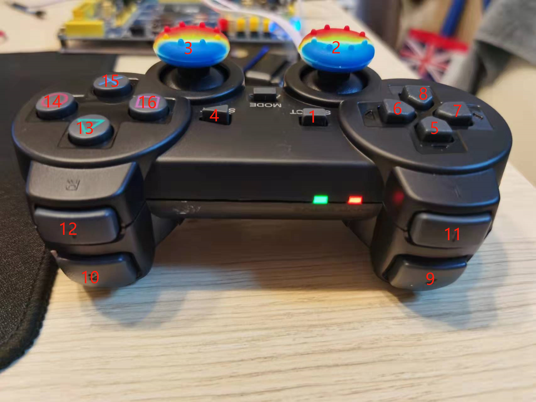
5. Determine whether the handle is a red light mode or a green light mode. After sending 0x01 0x42 to the handle by a single-chip computer, the value returned by the handle can be determined if the return is 0X41 for "green light mode" and 0x73 for "red light mode".
//Determine if it is a red light mode
//Return value; 0, red light mode
//Return value; 1, Green light mode
u8 PS2_RedLight(void)
{
	CS_L;
	PS2_Cmd(Comd[0]);  //Start command 0x01
	PS2_Cmd(Comd[1]);  //Request data 0x42
	CS_H;
	if( Data[1] == 0X73)   return 0 ;
	else return 1;
}
5. Single-chip computer receives handle data
//Read Handle Data
void PS2_ReadData(void)
{
	volatile u8 byte=0;
	volatile u16 ref=0x01;
	CS_L;
	PS2_Cmd(Comd[0]);  //Start command 0x01
	PS2_Cmd(Comd[1]);  //Request data 0x42

	for(byte=2;byte<9;byte++)          //Start accepting data
	{
		for(ref=0x01;ref<0x100;ref<<=1)
		{
			CLK_H;
			CLK_L;
			delay_us(50);
			CLK_H;
		      if(DI)
		      Data[byte] = ref|Data[byte];
		}
        delay_us(50);
	}
	CS_H;
}
A. Data transmission must be carried out during the CS pull-down period. After data transmission is completed, CS should also be pulled back to a high level for the next communication.
b. The single-chip computer sends 0x01 0x42 to the handle, at this time the handle will return 0x5A to the single-chip computer, which means that the request has been received and the data will be returned soon. So Data[2] saves the 0x5A returned by the handle. The latter Datas [3]-Data [8] all return the status information of keys and rockers.
6. Detect key state
//Processing the read PS2 data only handles the key part Default data is red light mode when only one key is pressed
//Press 0, not 1
u8 PS2_DataKey()
{
	u8 index;
	PS2_ClearData();
	PS2_ReadData();

	Handkey=(Data[4]<<8)|Data[3];     //This is 16 keys pressed 0, not 1
	for(index=0;index<16;index++)
	{
		if((Handkey&(1<<(MASK[index]-1)))==0)
		return index+1;
	}
	return 0;          //No key press
}
a. In the figure above, there are 16 keys for the handle, including two rockers, excluding the MODE key. The 16 keys are exactly two octal binaries. So use Data[3] and Data[4] to indicate the state of all keys.
b.u16 Handkey, this variable definition shows that Handkey is a 16-bit binary number, Handkey=(Data[4] < 8)|Data[3] indicates that the high eight digits of Handkey is Data[4], and the low eight digits are Data[3]

If I press SELECT, Data[3]=1111 1110B
If L2 is pressed, Data[4]=1111 1110B
So Handkey means 1111 1110 1111 1110B
C.For (index=0; index<16; index++) has 16 keys, so loop 16 times to determine which key was pressed.
If ((Handkey &(1<<(MASK[index]-1)==0) This function is analyzed from inside to outside 0<=index<=15, so 1<=MASK[index]<=16, so 0<=MASK[index]-1)<=15, and then converts 1 to 16-bit binary number: 0000 0000 0001B, so 1<<(MASK[index]-1) is moved one bit to the left and loops 15 times. It then runs with Handkey, and if 0, the key is pressed. The last index+1 is because the index is calculated from 0 and the keys are calculated from 1, so the last value returned needs to be + 1. But this function can only tell if a single key is pressed. If multiple keys are pressed, only the smaller number of keys can be detected. For example, if both direction (5) and START (4) are pressed at the same time, the return value is 4.
#define PSB_SELECT      1
#define PSB_L3          2
#define PSB_R3          3
#define PSB_START       4
#define PSB_PAD_UP      5
#define PSB_PAD_RIGHT   6
#define PSB_PAD_DOWN    7
#define PSB_PAD_LEFT    8
#define PSB_L2          9
#define PSB_R2          10
#define PSB_L1          11
#define PSB_R1          12
#define PSB_GREEN       13
#define PSB_RED         14
#define PSB_BLUE        15
#define PSB_PINK        16

u16 MASK[]={
	PSB_SELECT,
	PSB_L3,
	PSB_R3 ,
	PSB_START,
	PSB_PAD_UP,
	PSB_PAD_RIGHT,
	PSB_PAD_DOWN,
	PSB_PAD_LEFT,
	PSB_L2,
	PSB_R2,
	PSB_L1,
	PSB_R1 ,
	PSB_GREEN,
	PSB_RED,
	PSB_BLUE,
	PSB_PINK
};
7. Check the status of the rocker
#define PSS_RX 5
#define PSS_RY 6
#define PSS_LX 7
#define PSS_LY 8

//Get an analog of the rocker 	  Range 0~256
u8 PS2_AnologData(u8 button)
{
	return Data[button];
}
a.The feedback from the four rockers is analogue, ranging from 0x00 to 0xFF and converting to decimal is 0-255. The rocker's value is stored in Data[5], Data[6], Data[7], Data[8]
b. Note that the rocker only feeds back the simulation in red light mode and not in green light mode.
8. Other Functions
8.1 Clear data buffer
//Clear Data Buffer
void PS2_ClearData()
{
	u8 a;
	for(a=0;a<9;a++)
		Data[a]=0x00;
}
8.2 Handle Vibration Function
/******************************************************
motor1:Right side small vibration motor 0x00 off, other on
motor2:Left large vibration motor 0x40~0xFF motor on, the greater the value, the greater the vibration
******************************************************/
void PS2_Vibration(u8 motor1, u8 motor2)
{
	CS_L;
	delay_us(16);
    PS2_Cmd(0x01);  //Start Command
	PS2_Cmd(0x42);  //Request data
	PS2_Cmd(0X00);
	PS2_Cmd(motor1);
	PS2_Cmd(motor2);
	PS2_Cmd(0X00);
	PS2_Cmd(0X00);
	PS2_Cmd(0X00);
	PS2_Cmd(0X00);
	CS_H;
	delay_us(16);
}
8.3 Send Mode Settings
a. Line 8 PS2_Cmd(0x01) is the red light mode; PS2_Cmd(0x00) is green light mode;
b. Line 9 PS2_Cmd(0x03) can only switch traffic light mode through the instructions in line 8; PS2_Cmd(0xEE) can switch the traffic light mode by pressing MODE.
//Send Mode Settings
void PS2_TurnOnAnalogMode(void)
{
	CS_L;
	PS2_Cmd(0x01);
	PS2_Cmd(0x44);
	PS2_Cmd(0X00);
	PS2_Cmd(0x01); //analog=0x01;digital=0x00 Software Settings Send Mode
	PS2_Cmd(0xEE); //Ox03 lock settings, i.e. no mode can be set by pressing "MODE".
				   //0xEE does not lock the software settings, you can set the mode by pressing "MODE".
	PS2_Cmd(0X00);
	PS2_Cmd(0X00);
	PS2_Cmd(0X00);
	PS2_Cmd(0X00);
	CS_H;
	delay_us(16);
}