[STC15] interpretation of relevant registers of serial port 1
-
The data comes from STC15 manual.
-
Timer 2 is often used as a baud rate generator.
-
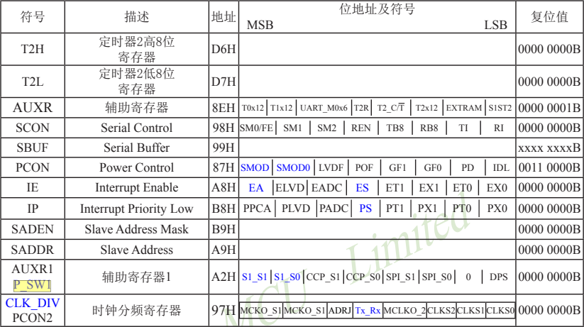
Control registers SCON and PCON of serial port 1
The serial port 1 of STC15 Series MCU is equipped with two control registers: serial control register SCON and baud rate selection special function register PCON.
The serial control register SCON is used to select the working mode of serial communication and some control functions. The format is as follows:
- SCON: serial control register (bit addressable)

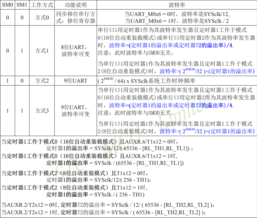
SMO/FE: when smod0 / PCON in PCON register When bit 6 is 1, this bit is used for frame error detection. When an invalid stop bit is detected, it is set through the UART receiver. It must be cleared by the software. - When smodo / PCON in PCON register When bit 6 is 0, this bit specifies the working mode of serial communication together with SM1, as shown in the following table.
SM0 and SM1 determine the working mode of serial port 1 according to the following combination:
- SM2: allow mode 2 or mode 3 multi machine communication control bit.
In mode 2 or mode 3, if the SM2 bit is 1 and the REN bit is 1, the receiver is in the address frame filtering state. At this time, the received 9th bit (i.e. RB8) can be used to filter the address frame: if RB8=1, it indicates that the frame is an address frame, the address information can enter SBUF and make RI 1, and then compare the address numbers in the interrupt service program; If RB8=0, it indicates that the frame is not an address frame, and RI=0 should be lost and maintained. In mode 2 or 3, if the SM2 bit is 0 and the REN bit is 1, the receiver is in the address frame filtering disabled state. Whether the received RB8 is 0 or 1, the received information can enter SBUF and make RI=1. At this time, RB8 is usually the check bit.
Mode 1 and mode 0 are non multi machine communication modes. In these two modes, SM2 should be set to 0. - REN: enable / disable serial reception control bit. Set REN by the software, i.e. REN=1 is the allowable serial receiving state, and the serial receiver RxD can be started to receive information. When the software resets REN, that is, REN=0, reception is prohibited.
- TB8: in mode 2 or mode 3, it is the 9th bit data to be sent, which is set or cleared by software as required. For example, it can be used as a check bit of data or a flag bit representing an address frame / data frame in multi machine communication. In mode 0 and mode 1, this bit is not used
RB8: in mode 2 or mode 3, the 9th bit of data received is used as the parity bit or the flag bit of address frame / data frame.
RB8 is not used in mode 0 (set SM2=0) RB8 is not used in mode 1 (set SM2=0, RB8 is the received stop bit). - TI: send interrupt request flag bit. In mode 0, when the 8th bit of serial transmission data ends, the internal hardware will automatically set it, i.e. TI=1, and request interrupt from the host. After responding to the interrupt, TI must be cleared by software, i.e. TI=0. In other ways, when the stop bit starts to be sent, it is set by the internal hardware, that is, TI=1. After responding to the interrupt, TI must be cleared by software.
- RI: receive interrupt request flag bit. In mode 0, when the end of bit 8 is received serially, the internal hardware automatically sets RI=1 and requests an interrupt from the host. After responding to the interrupt, RI must be cleared by software, that is, RI=0. In other ways, the intermediate time when the serial receives the stop bit is set by the internal hardware, that is, RI=1, and an interrupt application is sent to the CPU. After responding to the interrupt, RI must be cleared by the software.
- All bits of SCON can be reset to all "0" through the whole machine reset signal. The byte address of SCON is 98H, which can be addressed by bits. Each address is 98H~9FH, which can be set by software.
Interrupt request of serial communication: when a frame is sent, the internal hardware will automatically set TI, i.e. TI=1, and request interrupt processing; When a frame of information is received, the internal hardware will automatically set RI, i.e. RI=1, and request interrupt processing. Since TI and RI request an interrupt from the host in the "or logic" relationship, the host does not know whether it is the interrupt requested by TI or RI in advance when responding to the interrupt. TI and RI must be queried in the interrupt service program for discrimination, and then processed separately. Therefore, the two interrupt request flag bits cannot be set automatically by hardware, and must be cleared by software, otherwise there will be an error of one request and multiple responses.
SMOD / PCON in power control register PCON 7 is used to set whether the baud rate of mode 1, mode 2 and mode 3 is doubled.
- The format of power control register PCON is as follows:
- PCON: power control register (not bit addressable)

- SMOD: baud rate selection bit. When SMOD is set by software, that is, SMOD=1, the baud rate of serial communication modes 1, 2 and 3 is doubled; SMOD=0, the baud rate of each working mode will not be doubled. SMOD=0 during reset.
- SMOD0: frame error detection effective control bit. When SMOD0=1, the SM0/FE bit in the SCON register is used for the FE (frame error detection) function; When SMOD0=0, the SMO/FE bit in the SCON register is used for the SM0 function and specifies the working mode of the serial port together with SM1. SMOD0=0 during reset
- Other bits in PCON are independent of serial port 1 and will not be introduced here.
Serial port data buffer register SBUF
The address of serial port 1 buffer register (SBUF) of STC15 Series MCU is 99H, which is actually two buffers. The operation of writing SBUF completes the loading of data to be sent, and the operation of reading SBUF can obtain the received data. The two operations correspond to two different registers, one is a write only register and the other is a read-only register.
A data register is set in the serial channel. In all serial communication modes, SBUF signal (MOV, SBUF, a) is written
Under the control of, the data is loaded into the same 9-bit shift register. The first 8 bits are data bytes, and the lowest bit is the output bit of the shift register. According to different working modes, the value of "1" or TB8 will be automatically loaded into bit 9 of the shift register and sent
The receive register of the serial channel is an input shift register. In mode 0, its word length is 8 bits, and in other modes, it is 9 bits. When a frame is received, the data bytes in the shift register are loaded into the serial data buffer SBUF, and the 9th bit is loaded into the RB8 bit in the SCON register. If the received data is invalid due to SM2, the contents in RB8 and SBUF remain unchanged.
Since the input shift register and SBUF buffer are set in the receiving channel, the next frame information can be received immediately after a frame is received and the data is loaded from the shift register into the SBUF. The host should remove the data from the SBUF buffer before the frame is received, otherwise the data of the previous frame will be lost. The SBUF is sent to the internal data bus in parallel.
Auxiliary register AUXR
- AUXR: auxiliary register (not bit addressable)

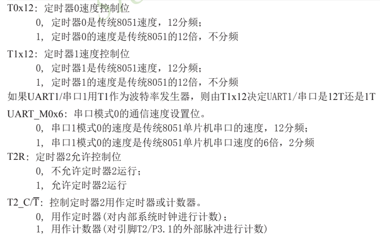
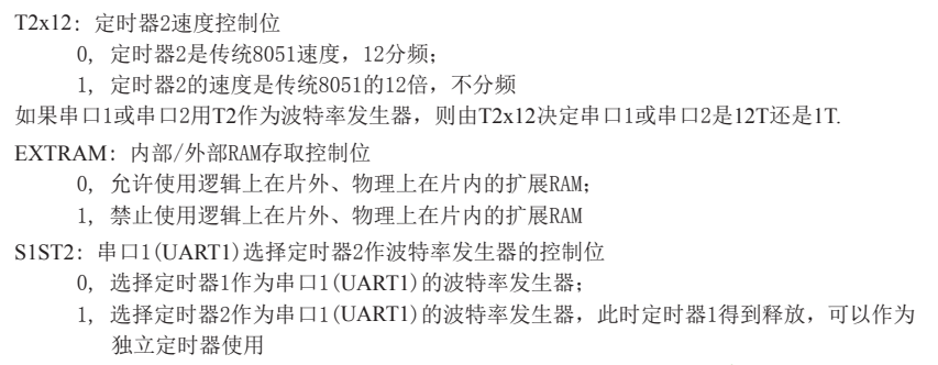
Serial port 1 can select timer 1 as baud rate generator or timer 2 as baud rate generator. When S1ST2 bit (serial port baud rate selection bit) in AUXR register is set to 1, serial port 1 selects timer 2 as baud rate generator. At this time, timer 1 can be released and used as timer / counter / clock output
For STC15 series single chip microcomputer, serial port 2 can only use timer 2 as its baud rate generator, and other timers cannot be selected as its baud rate generator; The serial port 1 selects timer 2 as its baud rate generator by default, and timer 1 can also be selected as its baud rate generator; By default, serial port 3 selects timer 2 as its baud rate generator, or timer 3 as its baud rate generator; By default, serial port 4 selects timer 2 as its baud rate generator, or timer 4 as its baud rate generator.
Registers T2H, T2L of timer 2
Timer 2 register T2H (address D6H, reset value 00H) and register T2L (address D7H, reset value 00H) are used to save the reload time constant.
Note: for STC15 Series MCU, serial port 2 can only use timer 2 as its baud rate generator, and other timers cannot be selected as its baud rate generator; The serial port 1 selects timer 2 as its baud rate generator by default, and timer 1 can also be selected as its baud rate generator; By default, serial port 3 selects timer 2 as its baud rate generator, or timer 3 as its baud rate generator; By default, serial port 4 selects timer 2 as its baud rate generator, or timer 4 as its baud rate generator.
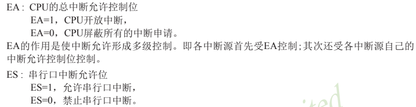
Register bits ES and PS associated with serial port 1 interrupt
The serial port interrupt permission bit ES is located in the interrupt permission register IE. the format of the interrupt permission register is as follows:
IE: interrupt enable register (bit addressable)

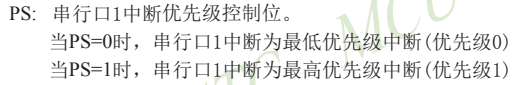
-IP: interrupt priority control register low (bit addressable)

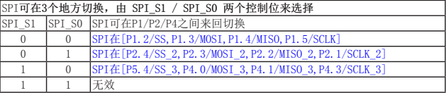
Register AUXR1 (P_SW1) for switching serial port 1

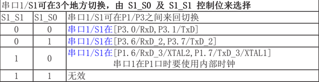
- Serial port 1 is recommended to be placed on [P3.6/RxD_2, P3.7/TxD_2] or [P1.6/RxD_3/XTAL2, P1.7/TxD_3/XTAL1].
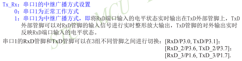
Relay broadcast mode setting bit of serial port 1 - TXRX / clkdiv four

Serial port 1 working mode 1: 8-bit UART, variable baud rate
When the software sets SM0 and SM1 of SCON to "01", serial port 1 works in mode 1. This mode is 8-bit UART format, and one frame information is 10 bits: 1-bit start bit, 8-bit data bit (low bit first) and 1-bit stop bit. If the baud rate is variable, it can be set as needed. TxD/P3.1 is sending information, RXD / P3 0 is the receiving end receiving information, and the serial port is the full duplex receiving / transmitting serial port.
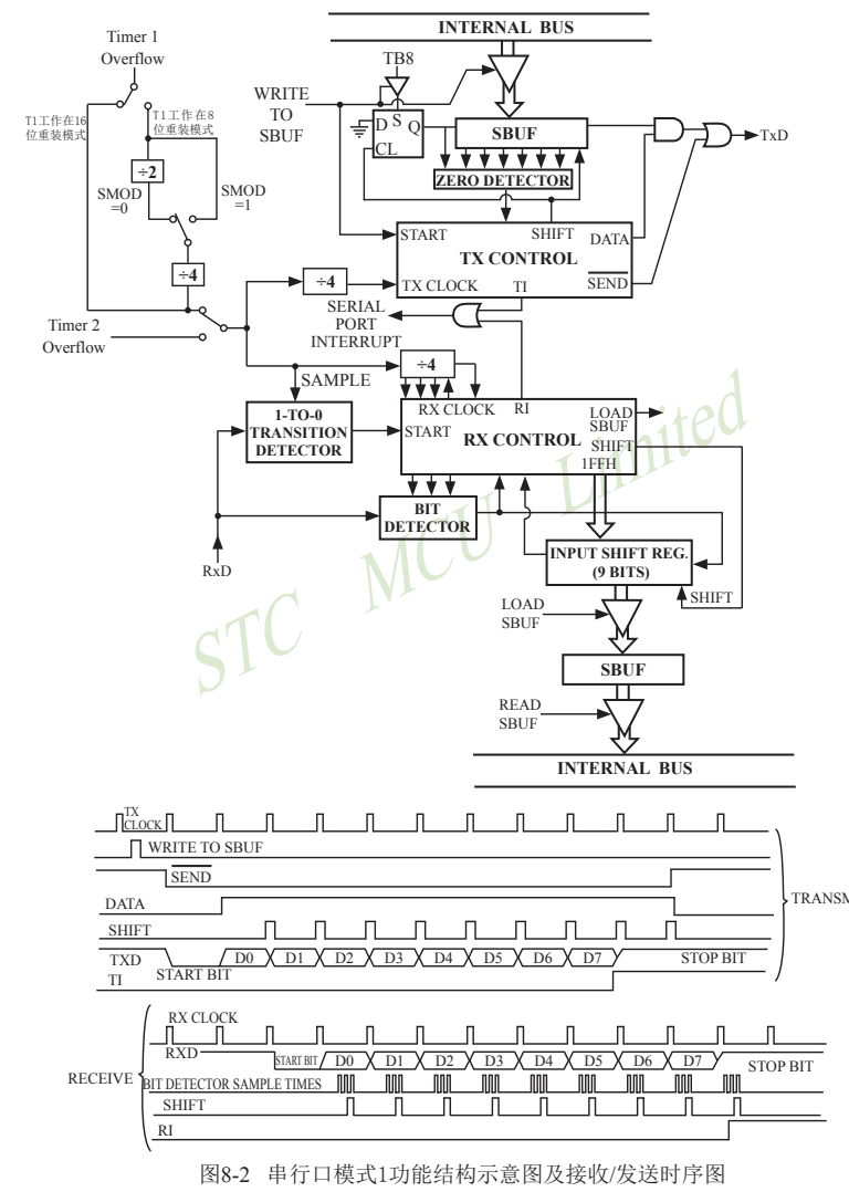
Transmission process of mode 1: when the serial communication mode is transmitted, the data is output by the serial transmitting terminal TxD. When the host executes an instruction to write "SBUF", it starts the transmission of serial communication. Writing "SBUF" signal also loads "1" into bit 9 of the transmission shift register and notifies TX control unit to start transmission. The timing of sending each bit is synchronized by the 16 frequency division counter.
The shift register continuously moves the data to the right and sends it to the TxD port, and continuously moves "0" to the left of the data as a supplement. When the highest displacement of the data reaches the output position of the shift register, the 9th bit "1" is immediately followed, and all bits on its left are "0". This state condition causes the TX control unit to make the last shift output, then invalidates the allowable transmission signal "SEND", completes the transmission of a frame of information, and sets the interrupt request bit TI, i.e. TI=1, to request interrupt processing from the host.
Receiving process of mode 1: when the software is set to receive the allowable flag bit REN, that is, REN=1, the receiver will sample the serial receiving port RxD at the rate of 16 frequency division of the selected baud rate. When the negative jump of RxD port from "1" → "0" is detected, the receiver will be started to receive data, reset the 16 frequency division counter immediately, and load 1FFH into the shift register. Reset the 16 frequency division counter to synchronize it with the input bit time.
The 16 states of the 16 frequency division counter are that 1 baud rate (each receiving time) is 16 equal parts. In the states of 7, 8 and 9 of each time, the detector samples the RxD port. The received value is the value of "two out of three" in this sampling, that is, the same value is sampled at least twice in three times, so as to eliminate the influence of interference and improve reliability. In the start bit, if the received value is not "0" (low level), the start bit is invalid. Reset the receiving circuit and re detect the jump of "1" ~ "0". If the received start bit is valid, input it into the shift register and receive the rest of the information of this frame.
The received data is moved in from the right side of the receiving shift register, and the loaded 1FFH is moved out to the left. When the start bit "0" is moved to the leftmost side of the shift register, the RX controller is shifted for the last time to complete the reception of one frame. If the following two conditions are met at the same time:
- ·RI=0;
- ·SM2=0 or the received stop bit is 1.
Then the received data is valid, load into SBUF, the stop bit enters RB8, set RI, i.e. RI=1, and request interrupt from the host. If the above two conditions cannot be met at the same time, the received data will be invalidated and lost. Whether the conditions are met or not, the receiver will detect the jump of "1" to "0" on RxD port again and continue to receive the next frame. The reception is valid. After the response is interrupted, the software must clear 0, i.e. RI=0. Normally, when serial communication works in mode 1, SM2 is set to "0".
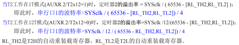
- The baud rate of serial communication mode 1 is variable. The variable baud rate is generated by timer / counter 1 or timer 2. Timer 2 is preferred to generate baud rate.
When serial port 1 uses timer 2 as its baud rate generator, baud rate of serial port 1 = (overflow rate of timer T2) / 4
(Note: the baud rate is also independent of SMOD.)
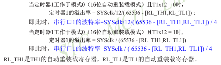
- When serial port 1 uses timer 1 as its baud rate generator and timer 1 operates in mode 0 (16 bit automatic reload mode), baud rate of serial port 1 = (overflow rate of timer 1) / 4
(Note: the baud rate has nothing to do with SMOD.)
Serial port sample program
/*************	Function description 	**************
 Instructions for use: confirm main before use_ FOSC (clock frequency) and baud rate
 Dual serial port full duplex interrupt mode transceiver communication program.
Set Timer2 as baud rate generator
 Send data to MCU through PC, and MCU will return the received data as it is through serial port

******************************************/


#define  	 MAIN_Fosc 			 16000000uL 	// Define master clock
#include "stdio.h"
#include	"STC15Fxxxx.H"

#define 		 BaudRate1 			 115200uL 		// Baud rate
#define		UART1_BUF_LENGTH	32
#define 		 Timer2_Reload 	 (65536UL -(MAIN_Fosc / 4 / BaudRate1)) 		// Timer2 reload value

u8	TX1_Cnt;	//Send count
u8	RX1_Cnt;	//Receive count
bit	B_TX1_Busy;	//Send busy flag

u8 	idata RX1_Buffer[UART1_BUF_LENGTH];	//Receive buffer


void	UART1_config();	// Select baud rate and use Timer2 as baud rate
 char putchar(unsigned char c);//Serial port printing function
//void 	PrintString1(u8 *puts);
void  delay_ms(unsigned int ms);//Delay Functions

//========================================================================
// Function: void main(void)
// Description: main function.
//========================================================================
void main(void)
{
	P1M1 |=0x00; P1M0 |=0x01;//Set P10 as push-pull output
//	P0M1 = 0; 	 P0M0 = 0; 	// Set as quasi two-way port
//	P1M1 = 0; 	 P1M0 = 0; 	// Set as quasi two-way port
//	P2M1 = 0; 	 P2M0 = 0; 	// Set as quasi two-way port
//	P3M1 = 0; 	 P3M0 = 0; 	// Set as quasi two-way port
//	P4M1 = 0; 	 P4M0 = 0; 	// Set as quasi two-way port
//	P5M1 = 0; 	 P5M0 = 0; 	// Set as quasi two-way port
//	P6M1 = 0; 	 P6M0 = 0; 	// Set as quasi two-way port
//	P7M1 = 0; 	 P7M0 = 0; 	// Set as quasi two-way port
	S1_USE_P30P31();
	UART1_config();	// Select baud rate, 2: use Timer2 as baud rate, other values: use Timer1 as baud rate
	EA = 1;	//Allow total interrupt

	printf("STC15F2K60S2 UART1 Test Prgramme!\r\n");	//UART1 sends a string

	while (1)
	{
		printf("\t perseverance51 \r\n");
		delay_ms(500);
		P10 = ~P10;
		if((TX1_Cnt != RX1_Cnt) && (!B_TX1_Busy))	//Receive data, send idle
		{
			SBUF = RX1_Buffer[TX1_Cnt];		//Return the received data as far as possible
			B_TX1_Busy = 1;
			if(++TX1_Cnt >= UART1_BUF_LENGTH)	TX1_Cnt = 0;
		}
	}
}


//========================================================================
// Function: void PrintString1(u8 *puts)
// Description: serial port 1 sends string function.
// Parameters: puts: string pointer
// Return: none
// Version: ver1 0
// Date: November 28, 2014
// remarks:
//========================================================================
///*
//void PrintString1(u8 *puts)	//Send a string
//{
//    for (; *puts != 0;	puts++)   	//End of stop character 0 encountered
//	{
//		SBUF = *puts;
//		B_TX1_Busy = 1;
//		while(B_TX1_Busy);
//	}
//}
//*/
//----------------------------------------------------------
//  Function name: putchar(unsigned char c)
//  Function function: Send a byte through serial port
//		Function: including stdio H realize printf printing
//----------------------------------------------------------
 char putchar(unsigned char c)
{
	     SBUF = c; 					//send data
			B_TX1_Busy = 1;
		while(B_TX1_Busy);
//     while(!TI);  					// Wait for sending to complete
//     TI=0;  							// Clear the sending flag bit;
	return c;
}

//========================================================================
// Function: void 	 UART1_config(u8 brt)
// Description: UART1 initialization function.
// Parameters: brt: select baud rate, 2: use Timer2 as baud rate, other values: use Timer1 as baud rate
// Return: none
// Version: ver1 0
// Date: November 28, 2014
// remarks:
//========================================================================
void	UART1_config()	// Select baud rate and use Timer2 as baud rate
{
	/*********** Baud rate use timer 2*****************/
		SCON = 0x50;		//8-bit data, variable baud rate
		AUXR |= 0x01;		//S1 BRT Use Timer2;
		AUXR |= 0x04;		//Timer clock 1T mode
	TH2 = Timer2_Reload	 / 256;
	TL2 = Timer2_Reload	 % 256;
		AUXR |= 0x10;		//Timer 2 starts timing

//SCON = (SCON & 0x3f) | 0x40; 	// UART1 mode, 0x00: synchronous shift output, 0x40: 8-bit data, variable baud rate, 0x80: 9-bit data, fixed baud rate, 0xc0: 9-bit data, variable baud rate
//	PS  = 1; 	// High priority interrupt
	ES  = 1;	//Allow interrupt
	REN = 1;	//Allow to receive
	P_SW1 &= 0x3f;//Serial port at [P3.0/RxD,P3.1/TxD]
	P_SW1 |= 0x00;		//UART1 switch to, 0x00: P3.0 P3.1, 0x40: P3.6 P3.7, 0x80: P1.6 P1.7 (internal clock must be used)
//	PCON2 |=  (1<<4); 	// Internal short circuit RXD and TXD, relay, ENABLE,DISABLE
	PCON2 &=0x3f;//The master clock does not output external clock,
	B_TX1_Busy = 0;
	TX1_Cnt = 0;
	RX1_Cnt = 0;
}


//========================================================================
// Function: void UART1_int (void) interrupt UART1_VECTOR
// Description: UART1 interrupt function.
// Parameter: nine
// Return: none
// Version: ver1 0
// Date: November 28, 2014
// remarks:
//========================================================================
void UART1_int (void) interrupt UART1_VECTOR
{
	if(RI)
	{
		RI = 0;
		RX1_Buffer[RX1_Cnt] = SBUF;
		if(++RX1_Cnt >= UART1_BUF_LENGTH)	RX1_Cnt = 0;	//Anti overflow
	}

	if(TI)
	{
		TI = 0;
		B_TX1_Busy = 0;
	}
}

//========================================================================
// Function: void delay_ ms(unsigned char ms)
// Description: delay function.
// Parameter: ms, the number of MS to delay. Only 1 ~ 255 MS is supported here Automatically adapt to the master clock
// Return: none
// Version: ver1 0
// Date: April 1, 2013
// remarks:
//========================================================================
void  delay_ms(unsigned int ms)
{
     unsigned int i;
	 do{
	      i = MAIN_Fosc / 13000;
		  while(--i)	;   //14T per loop
     }while(--ms);
}