1, Preparatory work: (1) download the generated source package on the smart cloud
(2) a wifi module. This routine uses (ESP8266 module of punctual atom)
(3) a development board and core board of STMF103 (STM32F103C8T6 upgrade board)
(4) a keil project, which transplants the source code of Ji Zhi cloud to the project
Source package:
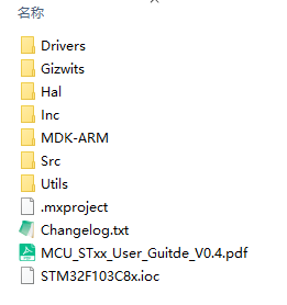
2, In the source code, we mainly focus on two files
1.Gizwits
2.Utils
3, Focus on Revising two c Documents
1.gizwits_product.c 2.gizwits_protocol.c
4, Migration steps
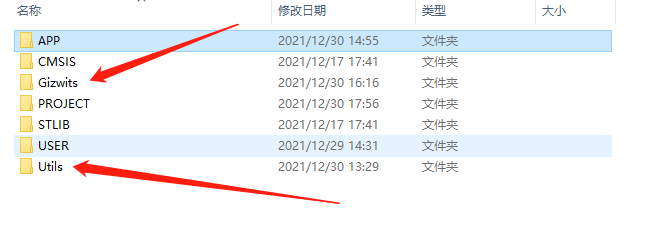
1. Copy the Gizwits and Utils folders into your own project directory. The following figure shows my first level project directory.
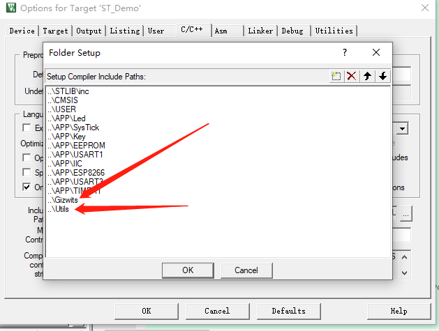
2. Import the under these two directories in keil c and h file.

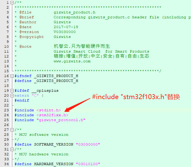
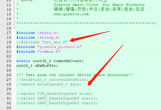
3. After adding it into our project, there will be errors in compilation. The reason for the error is that some are not found h file or function, so we directly delete or replace these.
At gizwits_product.h #include < stm32f1xx h> Replace with the header file of our MCU. I use #include "stm32f103x.h"
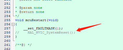
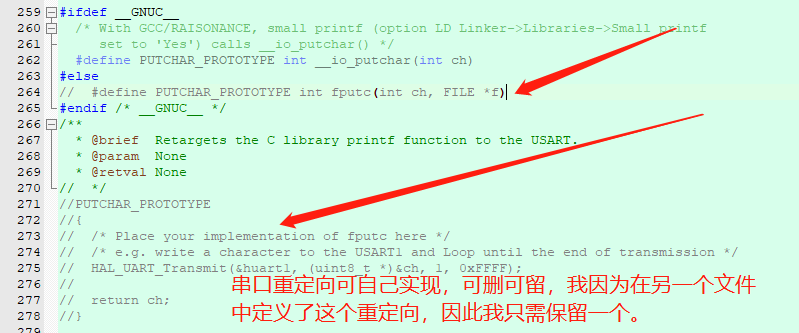
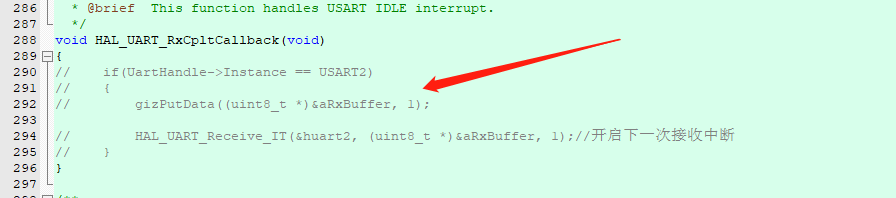
4. At gizwits_ product. There are some programs deleted in the C file
At this point, we will basically complete the deletion of transplantation. The following is to realize a 1ms timer and a serial port for communication with WIFI module.
5. Timer implementation (complete program)
(1) Timer initialization
/*timer2.c*/

/*Timer TIM2*//* TIM2 Interrupt priority configuration */
void TIM2_NVIC_Configuration(void)
{
    NVIC_InitTypeDef NVIC_InitStructure;

    NVIC_PriorityGroupConfig(NVIC_PriorityGroup_0);
    NVIC_InitStructure.NVIC_IRQChannel = TIM2_IRQn;
    NVIC_InitStructure.NVIC_IRQChannelPreemptionPriority = 0;
    NVIC_InitStructure.NVIC_IRQChannelSubPriority = 3;
    NVIC_InitStructure.NVIC_IRQChannelCmd = ENABLE;
    NVIC_Init(&NVIC_InitStructure);
}


/*The interruption period is 1ms*/
void TIM2_Configuration(void)
{
    TIM_TimeBaseInitTypeDef  TIM_TimeBaseStructure;
    RCC_APB1PeriphClockCmd(RCC_APB1Periph_TIM2 , ENABLE);
    TIM_DeInit(TIM2);
    TIM_TimeBaseStructure.TIM_Period=1000;    //The value of the automatic reload register cycle(Count value)
    /* Cumulative Tim_ An update or interrupt is generated after a period frequency */
    TIM_TimeBaseStructure.TIM_Prescaler= (72 - 1);    //Clock prescaled frequency 72 M/72
    TIM_TimeBaseStructure.TIM_CounterMode=TIM_CounterMode_Up; //Count up mode
    TIM_TimeBaseInit(TIM2, &TIM_TimeBaseStructure);
    TIM_ClearFlag(TIM2, TIM_FLAG_Update);    // Clear overflow interrupt flag
    TIM_ITConfig(TIM2,TIM_IT_Update,ENABLE);
    TIM_Cmd(TIM2, ENABLE);    // Turn on the clock
    RCC_APB1PeriphClockCmd(RCC_APB1Periph_TIM2 , DISABLE);    //Close for use first
}

void TIM2_Init(void)
{
        TIM2_NVIC_Configuration(); /* TIM2 Timing configuration */
        TIM2_Configuration();
        START_TIME;     /* TIM2 Start timing */
}
(2) Implement timer switch (personal)
/*timer2.h*/

#include "stm32f10x.h"

#define START_TIME  RCC_APB1PeriphClockCmd(RCC_APB1Periph_TIM2 , ENABLE);TIM_Cmd(TIM2, ENABLE)
#define STOP_TIME  TIM_Cmd(TIM2, DISABLE);RCC_APB1PeriphClockCmd(RCC_APB1Periph_TIM2 , DISABLE)

void TIM2_NVIC_Configuration(void);
void TIM2_Configuration(void);
void TIM2_Init(void);
(3) Interrupt processing, gizTimerMs(); In the #include "gizwits_product.h" file, the timing of WIFI system is realized.
void TIM2_IRQHandler(void)
{
    if ( TIM_GetITStatus(TIM2 , TIM_IT_Update) != RESET )
    {
                gizTimerMs();
                TIM_ClearITPendingBit(TIM2 , TIM_FLAG_Update);
    }
}
6. Serial port implementation
(1) Serial port initialization (USART3)
/*usart3.c*/
void USART3_Config(u32 BaudRate)
{
        GPIO_InitTypeDef GPIO_InitStruct;
        USART_InitTypeDef USART_InitStruct;
        NVIC_InitTypeDef NVIC_InitStruct;

        /*Turn on USART3 clock*/
        RCC_APB1PeriphClockCmd(RCC_APB1Periph_USART3,ENABLE);
        /*Turn on the CPIOB clock*/
        RCC_APB2PeriphClockCmd(RCC_APB2Periph_GPIOB,ENABLE);

        GPIO_InitStruct.GPIO_Mode = GPIO_Mode_AF_PP;
        GPIO_InitStruct.GPIO_Pin = GPIO_Pin_10;  //Tx
        GPIO_InitStruct.GPIO_Speed = GPIO_Speed_10MHz;
        GPIO_Init(GPIOB, &GPIO_InitStruct);

        GPIO_InitStruct.GPIO_Mode = GPIO_Mode_IN_FLOATING;
        GPIO_InitStruct.GPIO_Pin = GPIO_Pin_11;        //Rx
        GPIO_InitStruct.GPIO_Speed = GPIO_Speed_10MHz;
        GPIO_Init(GPIOB, &GPIO_InitStruct);

        /*set baud rate*/
        USART_InitStruct.USART_BaudRate = BaudRate;
        /*Do not use hardware streaming*/
        USART_InitStruct.USART_HardwareFlowControl = USART_HardwareFlowControl_None;
        /*RX TX All enable*/
        USART_InitStruct.USART_Mode = USART_Mode_Tx | USART_Mode_Rx;
        /*Do not use verification*/
        USART_InitStruct.USART_Parity = USART_Parity_No;
        /*1 Bit stop bit*/
        USART_InitStruct.USART_StopBits = USART_StopBits_1;
        /*8 Digit data bit*/
        USART_InitStruct.USART_WordLength = USART_WordLength_8b;
        /*Initialize USART*/
        USART_Init(USART3, &USART_InitStruct);
        /*Clear the pending flag of USARTx*/
        USART_ClearFlag(USART3, USART_IT_RXNE);
        /*Open the interrupt event. When the reception is not empty, open the interrupt*/
        USART_ITConfig(USART3,USART_IT_RXNE,ENABLE);
        /*Specifies the interrupt source, which can also be regarded as the interrupt number*/
        NVIC_InitStruct.NVIC_IRQChannel = USART3_IRQn;
        /*Interrupt enable*/
        NVIC_InitStruct.NVIC_IRQChannelCmd = ENABLE;
        /*Set interrupt priority type*/
        NVIC_InitStruct.NVIC_IRQChannelPreemptionPriority = 2;
        /*Set interrupt priority*/
        NVIC_InitStruct.NVIC_IRQChannelSubPriority = 2;
        /*Initialize interrupt vector*/
        NVIC_Init(&NVIC_InitStruct);
        /*Enable USART3*/
        USART_Cmd(USART3,ENABLE);
}
(2) Send function
/*usart3.c*/

/*send data*/
void USART3_Send(u8 *buf,uint16_t len)
{
        u16 t;

        for(t = 0;t < len;t++) //Circular transmission
        {
                /*Detect that the current serial port is idle*/
                while(USART_GetFlagStatus(USART3,USART_FLAG_TC) == RESET);
                USART_SendData(USART3,buf[t]);//send out USARTx Data
        }
        /*Wait for sending to complete*/
        while(USART_GetFlagStatus(USART3,USART_FLAG_TC) == RESET);
}
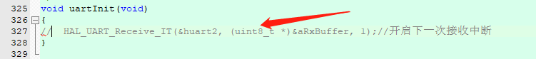
(3) Interrupt receiving function
#include "gizwits_protocol.h"

extern uint8_t aRxBuffer;  //This parameter is in gizwits_product.c Defined in
//Serial port interrupt function
void USART3_IRQHandler()
{
                /*Wait for sending to complete*/
                while(USART_GetFlagStatus(USART3,USART_FLAG_TC));
                /*receive data */
                aRxBuffer = USART_ReceiveData(USART3);
                /*Wait for reception to complete*/
                gizPutData((uint8_t *)&aRxBuffer,1);
                /*Clear middle break*/
                USART_ClearITPendingBit(USART3,USART_IT_RXNE); //eliminate USARTx Interrupt hold bit for
}
(4)usart3.h
#ifndef __USART3_H__
#define __USART3_H__

#include "stm32f10x.h"

void USART3_Config(u32 BaudRate);
void USART3_Send(u8 *buf,uint16_t len);

#endif
6. One click distribution network setting is to realize a key function and call the distribution network function. The distribution network function is #include int32 in "gizwits_product. H"_ t gizwitsSetMode(uint8_t mode).
(1)key.c
#include "key.h"
#include "led.h"
#include "SysTick.h"
#include "usart1.h"
#include "E2prom.h"
#include "EPS8266.h"
#include "gizwits_product.h"

void Key_GPIO_Config(void)
{
    GPIO_InitTypeDef GPIO_InitStructure;
    RCC_APB2PeriphClockCmd(RCC_APB2Periph_GPIOA, ENABLE); // Enable PC Port clock

    GPIO_InitStructure.GPIO_Pin = KEY_PIN;                        //Select the corresponding pin
    GPIO_InitStructure.GPIO_Mode = GPIO_Mode_IPU;     //Pull up input
    GPIO_InitStructure.GPIO_Speed = GPIO_Speed_50MHz;
    GPIO_Init(KEY_IOA, &GPIO_InitStructure);                   //initialization PC port
}

/*******************************************************************************
* Function name: KEY_Scan
* Function: key scanning detection
* Input: mode=0: press the key once
                     mode=1: Press the key continuously
* Output: 0: no key pressed
                     KEY_UP_PRESS: KEY_UP Key press
                     KEY0_PRESS: KEY0 Key press
                     KEY1_PRESS: KEY1 Key press
*******************************************************************************/
unsigned char Key_Scan(u8 mode)
{
    static unsigned char KeyUp_En = 1;

        if(mode == 1)KeyUp_En = 1;

    if((KeyUp_En==1) && (KEY_UP == 0))
    {
                delay_ms(20);
        KeyUp_En = 0;
        if(KEY_UP == 0)
        {
                        LED2(0);
                        gizwitsSetMode(WIFI_AIRLINK_MODE);  //One key distribution network
                        return KEY_UP_PRESS;
        }
    }
    else if((KeyUp_En==0) &&(KEY_UP == 1))KeyUp_En = 1;
        return 0;
}
(2)Key.h
#ifndef __KEY_H__
#define __KEY_H__

#include "system.h"

#define KEY_PIN    GPIO_Pin_0
#define KEY_IOA    GPIOA

#define KEY_UP PAin(0)

#define KEY_UP_PRESS 1

extern void Key_GPIO_Config(void);
extern unsigned char Key_Scan(u8 mode);

#endif
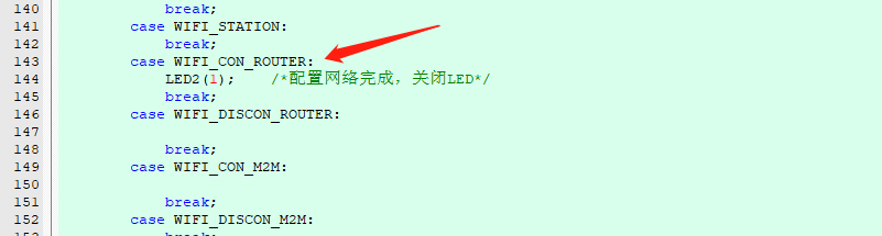
The LED will be turned on during distribution. If the distribution is successful, the LED will be turned off. At gizwits_ product. In the gizwitsEventProcess() function in C. This function is the core of the whole system, which completes the data transfer processing, data reporting and system state detection.
V. gizwits_product.c file function improvement.
(1) Report information collection function. Here I have only one data reporting point (temperature value), so I have only one parameter.
/*Collect data to be reported, such as temperature, humidity, etc*/
void userHandle(void)
{
       currentDataPoint.valueTEMP = MyTemp;//Add Sensor Data Collection
}
(2) calling the serial initialization and timer initialization function of the file in userInit(void).
void userInit(void)
{
memset((uint8_t*)¤tDataPoint, 0, sizeof(dataPoint_t));
timerInit();
uartInit();
}
(3)timerInit();
void timerInit(void)    //timer initiated
{
    TIM2_Init();
}
(4)uartInit();
/**
* @brief USART init function

* Serial communication between WiFi modules and device MCU
* @param none
* @return none
*/
void uartInit(void) //Serial port initialization
{
    USART3_Config(9600);
}
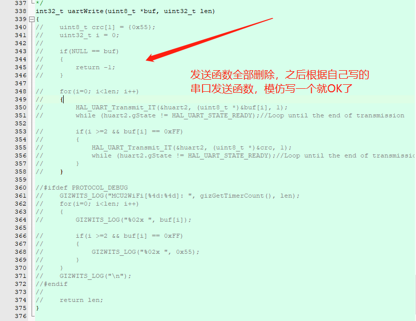
(5) Send function
/**
* @brief Serial port write operation, send data to WiFi module
*
* @param buf      : buf address
* @param len      : buf length
*
* @return : Return effective data length;-1,return failure
*/
int32_t uartWrite(uint8_t *buf, uint32_t len)
{
    uint32_t i = 0;
    uint8_t crc = 0x55;

    if(NULL == buf)
    {
        return -1;
    }

    for(i = 0; i < len; i++)
    {
        USART3_Send(buf+i,1);
        if(i >= 2  && buf[i] == 0xFF)
        {
            USART3_Send(&crc,1);
        }
    }
    return len;
}
6, Main C Documents
#include "stm32f10x.h" #include "led.h" #include "SysTick.h" #include "key.h" #include "E2prom.h" #include "usart1.h" #include "usart3.h" #include "Timer1.h" #include "gizwits_product.h" #include "common.h" int main(void) { SystemInit(); // Configure the system clock to 72 M userInit(); gizwitsInit(); while(1) { userHandle(); //In this function, data reporting and downlink processing are realized gizwitsHandle((dataPoint_t *)¤tDataPoint); //Report data } }
So far, the migration to STM32F103 is completed. Interested students who want to know how to distribute WIFI network can refer to the corresponding materials and source programs.