Catalog
5. CubeMX+HAL Open Serial Interrupt
7. Clock Tree Basic Operations
8. Universal timer configuration
(1) Set the timer clock to 72M
Timer interrupt callback function: (smoothing filter)
1. Set up GPIO:
(1) Set PA8 as output, push-pull up, initial state is high level:
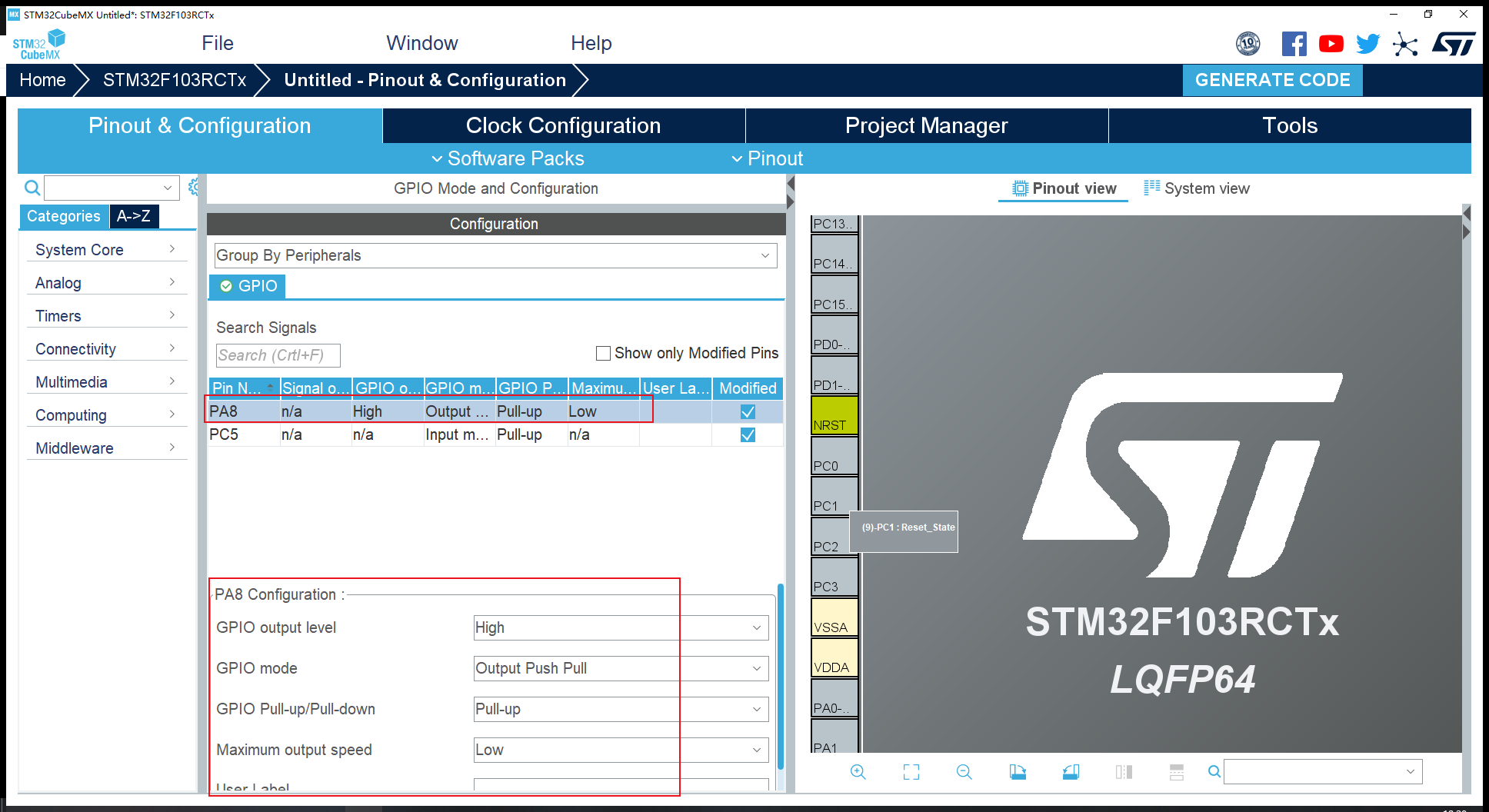
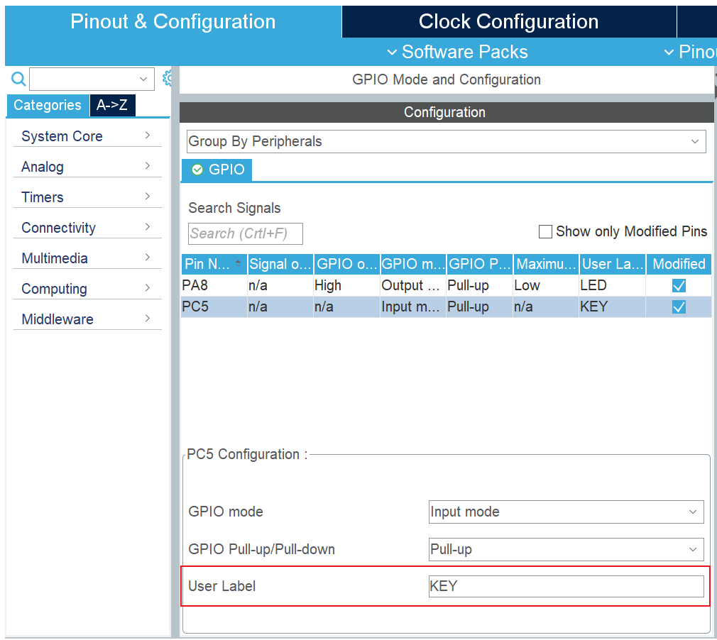
(2) Using User Label inside pin configuration, you can generate corresponding macros, improve code reuse, and facilitate portability.
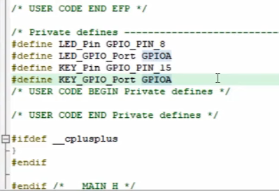
In the corresponding project code, there are macro definitions as follows:
2. printf redirection
int fputc(int ch, FILE *f)
{
	uint8_t temp[1] = {ch};
	HAL_UART_Transmit(&huart1, temp, 1, 2);
	return ch;
}
3. Log information format
Refer to the current mainstream embedded, Android and other output methods:
[log level] File name: Log information
//Example: [info] main. C: init ok!
//Example: [debug] adc. C: adc_ GetValue -> 3.3V
(1) Conditional compilation can be used to decide whether to print Log information:
#Define Log 1 // Change to 0 if you don't want to print


#if Log
printf("[info]main.c:init!\r\n");
#endif
(2) Variable parameter macros
#define USER_MAIN_DEBUG


#ifdef USER_MAIN_DEBUG


#define user_main_printf(format, ...) printf( format "\r\n",##__VA_ARGS__)

#define user_main_info(format, ...) printf("[main]info:" format "\r\n",##__VA_ARGS__)

#define user_main_debug(format, ...) printf("[main]debug:" format "\r\n",##__VA_ARGS__)

#define user_main_error(format, ...) printf("[main]error:" format "\r\n",##__VA_ARGS__)

#else

#define user_main_printf(format, ...)

#define user_main_info(format, ...)

#define user_main_debug(format, ...)

#define user_main_error(format, ...)

#endif
define a USER_when I need to print serial information MAIN_ DEBUG, comment it out when I don't need it.
4. Personalized Output
You can use this website to design characters: http://patorjk.com/software/taag/
printf(".__           .__  .__                            .__       .___");
printf("|  |__   ____ |  | |  |   ______  _  _____________|  |    __| _/");
printf("|  |  \\_/ __ \\|  | |  |  /  _ \\ \\/ \\/ /  _ _  __ \\  |   / __ | ");
printf("|   Y  \\  ___/|  |_|  |_(  <_> )     (  <_> )  | \\/  |__/ /_/ | ");
printf("|___|  /\\___  >____/____/\\____/ \\/\\_/ \\____/|__|  |____/\\____ |");
printf("     \\/     \\/                                               \\/");
5. CubeMX+HAL Open Serial Interrupt
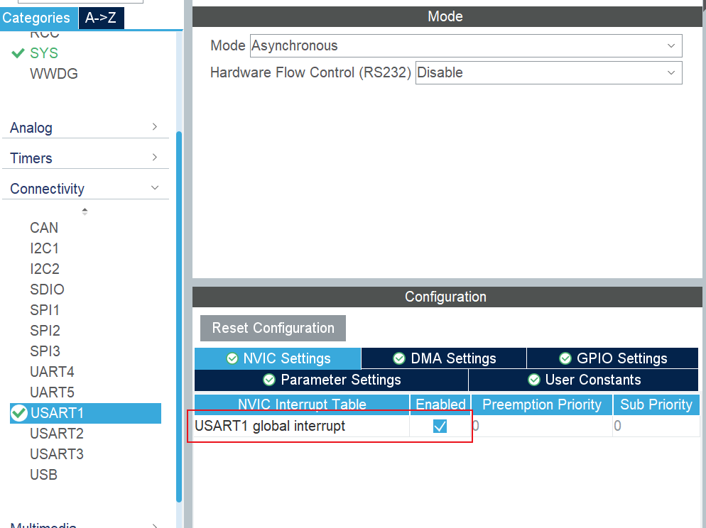
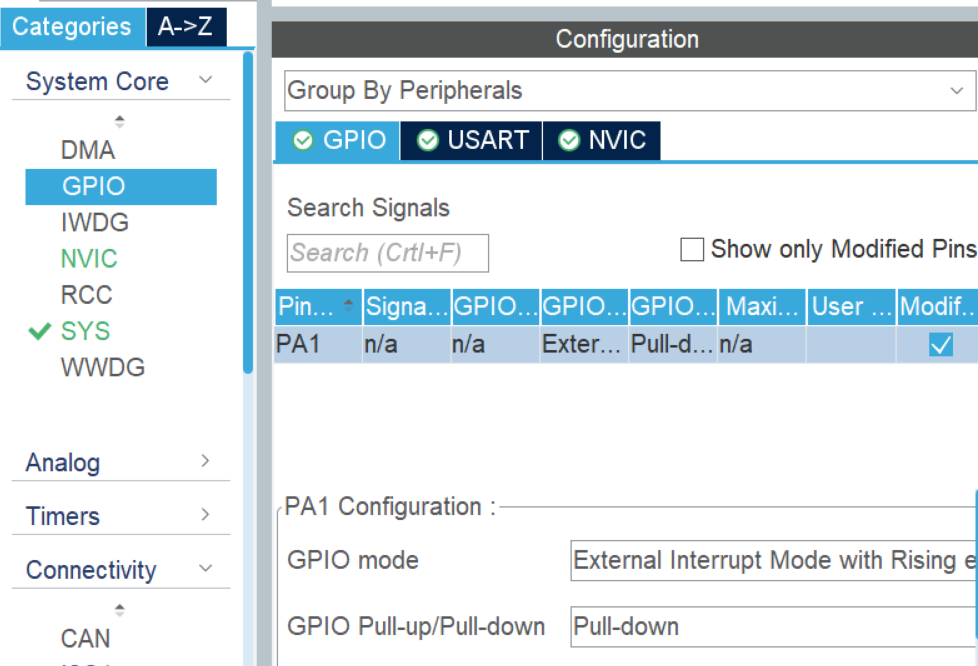
6. Open external interrupt
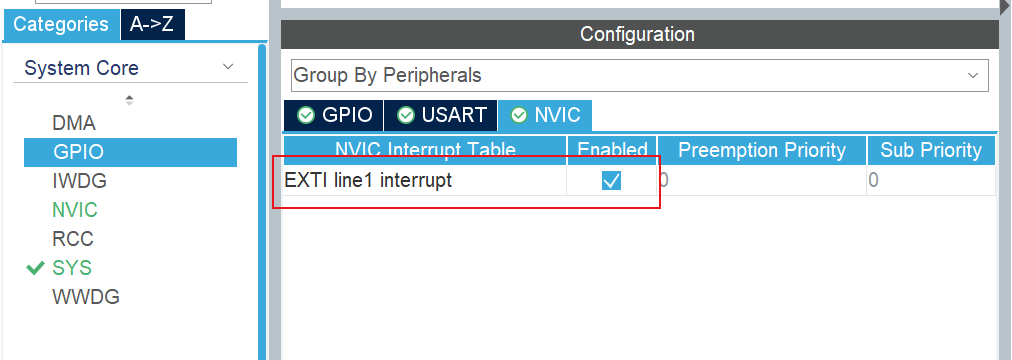
In addition, the GPIO configuration for EXTI external interrupts is as follows: default drop-down, rise edge trigger.
Then write a callback function for the external interrupt.
eg: measure the frequency of pwm.
In 1s time, the number of rise edges is the frequency. That is, the number of times an external interrupt enters within a second is the frequency. Pwm_for each interrupt The value of value plus 1,1s is the frequency.
When there is a rising edge, entering an external interrupt will pwm_value plus 1.
int pwm_value = 0;
int main()
{
pwm_value = 0;
HAL_Delay(1000); # Pwm_obtained after a delay of 1 s Value is the frequency value
printf("[\tmain]info:pwm_value = %d\r\n", pwm_value);
}
# Callback function for external interruption
void HAL_GPIO_EXTI_Callback(uint16_t GPIO_Pin)
{
if(GPIO_Pin == PWM_Pin) # Determine if triggered pins are defined pins
{
pwm_value++;
}
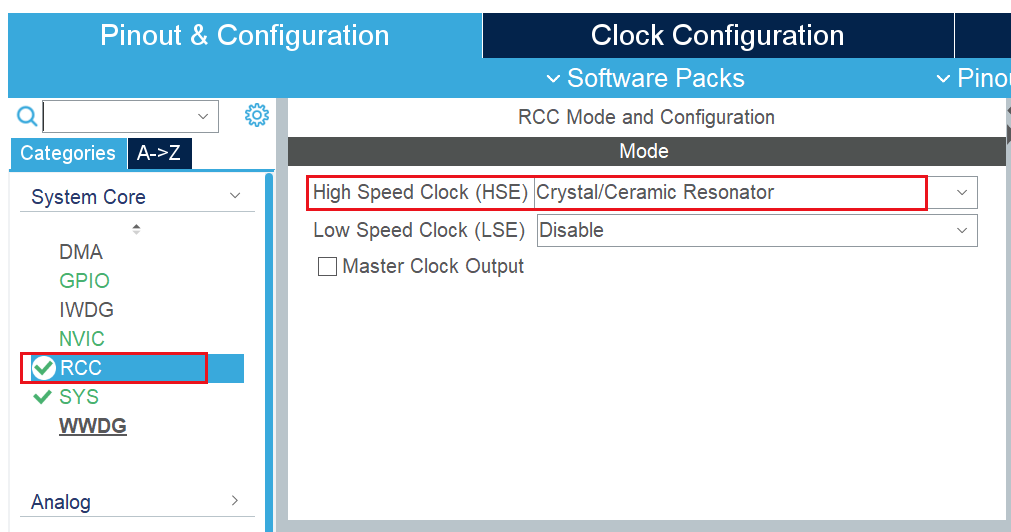
}7. Clock Tree Basic Operations
(1) Enable external clock source
Generally, the internal clock is used by default in the generated project, so the external clock is enabled first.
(2) Then set the HCLK clock frequency to the maximum, for example, the maximum of f103 is 72M, and the maximum of f406 is 84M.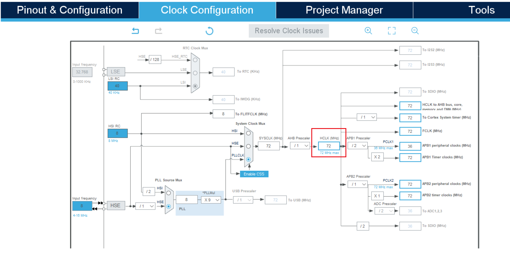
(3) Finally, on-demand frequency division for different peripherals.
8. Universal timer configuration
eg: Flip the LED at a specific time.
# Overflow Time
Tout = (arr+1)*(psc+1)/Tclk
Frequency: Tclk/(psc+1) MHz
void Timer3_Init(uint16_t arr,uint16_t psc)
{
TIM_TimeBaseInitTypeDef TIM_TimeBaseStructure;
NVIC_InitTypeDef NVIC_InitStructure;
RCC_APB1PeriphClockCmd(RCC_APB1Periph_TIM3, ENABLE); //Clock Enabling
TIM_TimeBaseStructure.TIM_Period = arr; //Set the value of the auto reload register cycle for the next update event load activity Count to 5000 to 500 ms
TIM_TimeBaseStructure.TIM_Prescaler =psc; //Set the counting frequency of the pre-divided frequency value 10Khz used as the TIMx clock frequency divisor
TIM_TimeBaseStructure.TIM_ClockDivision = 0; //Set clock division: TDTS = Tck_tim
TIM_TimeBaseStructure.TIM_CounterMode = TIM_CounterMode_Up; //TIM Up Count Mode
TIM_TimeBaseInit(TIM3, &TIM_TimeBaseStructure); //According to TIM_ Unit of time base for initializing TIMx with parameters specified in TimeBaseInitStruct
TIM_ITConfig(TIM3,TIM_IT_Update|TIM_IT_Trigger,ENABLE); //Timer interrupt enable
NVIC_PriorityGroupConfig(NVIC_PriorityGroup_2); //Set NVIC interrupt grouping 2:2 bit preemption priority, 2 bit response priority
NVIC_InitStructure.NVIC_IRQChannel = TIM3_IRQn; //TIM3 Interruption
NVIC_InitStructure.NVIC_IRQChannelPreemptionPriority = 0x01; //Priority Level 1
NVIC_InitStructure.NVIC_IRQChannelSubPriority = 0x01; //From Priority Level 3
NVIC_InitStructure.NVIC_IRQChannelCmd = ENABLE; //IRQ Channel Enabled
NVIC_Init(&NVIC_InitStructure); //According to NVIC_ Parameters specified in InitStruct initialize peripheral NVIC registers
TIM_Cmd(TIM3, ENABLE); //Enable TIMx peripherals
}
void TIM3_IRQHandler(void) //TIM3 Interruption
{
static uint8_t cnt = 0; //Static variable
if (TIM_GetITStatus(TIM3, TIM_IT_Update) != RESET) //Check whether the specified TIM interrupt occurs or not: TIM interrupt source
{
/*Interrupt operation*/
cnt++;
TIM_ClearITPendingBit(TIM3, TIM_IT_Update ); //Clear interrupt pending bits for TIMx: TIM interrupt source
}
if(cnt == 10)
{
LED = ~LED;
cnt = 0;
}
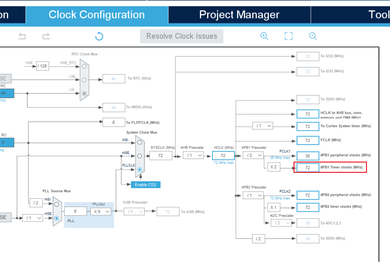
}9. CubeMX Configuration Timer
(1) Set the timer clock to 72M
(2) Select internal clock
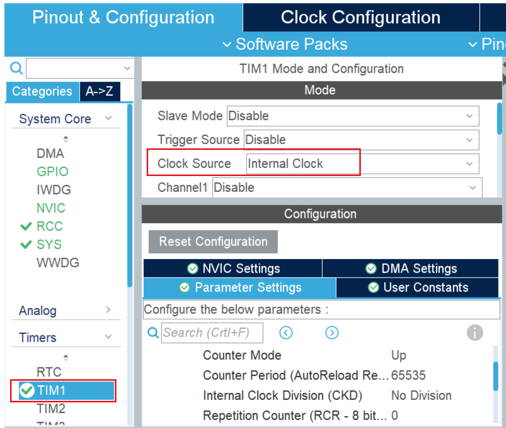
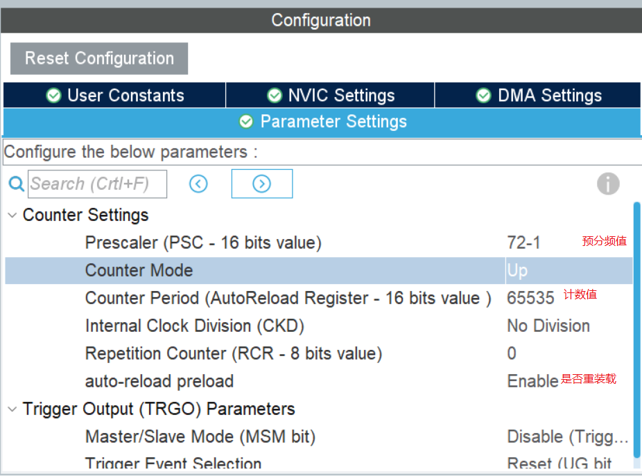
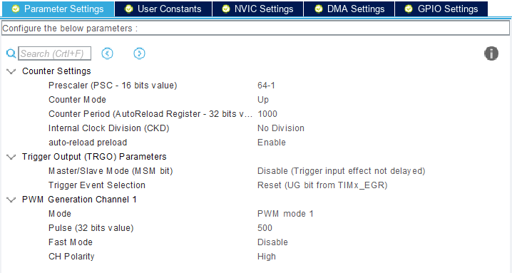
(3) Configure timer
Main configurations: Timing time, and whether to reset the timer.
Timer frequency = Timer clock /(Pre-frequency + 1)/(Count value + 1) Hz.
Timing time = 1/Timing frequency s.
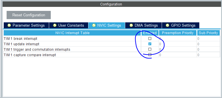
(4) Open interrupt
Basic timer:
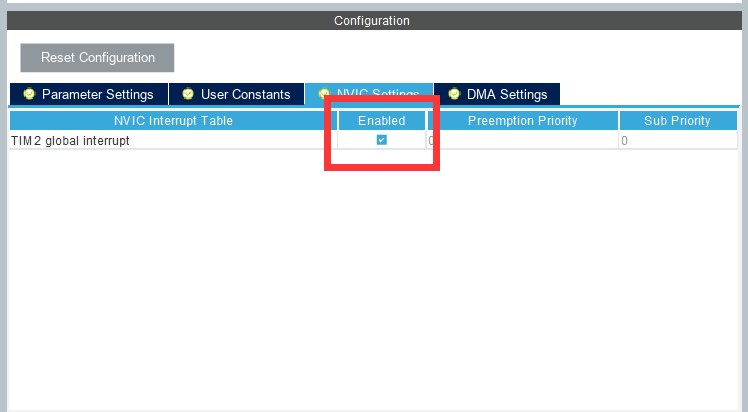
Advanced timer:
Timer interrupt callback function: (smoothing filter)
eg: Smooth Filter - Let the sampled value be filtered all the time by another "thread" and take its value directly when needed.
void HAL_TIM_PeriodElapsedCallback(TIM_HandleTypeDef *htim)
{
    if(htim->Instance == htim1.Instance)
    {
        pwm_sum += pwm_value * 10;  //pwm_sum accumulation
        pwm_sum -= pwm_avg;         //pwm_sum minus the last average
        pwm_avg = pwm_sum * 1.0 / 5; //Update the average of pwm
        pwm_value_final = pwm_avg;   //pwm_value_final is the current pwm frequency
        pwm_value = 0;               //Will pwm_value empty, recalculate
    }
}
10. CubeMX Configuration pwm
(1) Enabling PWM channels
Here, the Channel1 of TIM2 is set as the PWM output channel.
(PWM Generation CHx Forward, PWM Generation CHxN Reverse, PWM Generation CHx CHxN Pair Complementary pwm Output)
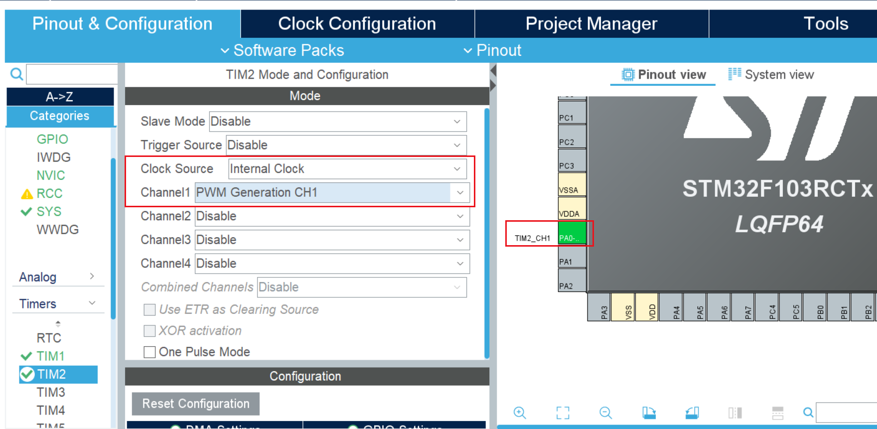
(2) Configuration frequency and duty cycle
Frequency = Timer Clock/ (Prescaler + 1) / (Cound Period + 1) Hz
Duty Cycle = Pulse / Cound Period Count%
(3) Subordinate code implements a process where the pwm duty cycle gradually increases to 1 and then becomes 0.
int main(void)
{
    int pwm = 0;

    HAL_Init();

  /* Configure the system clock */
    SystemClock_Config();

  /* Initialize all configured peripherals */
    MX_GPIO_Init();
    MX_TIM1_Init();

    # Channel 1 enabling Tim 1
    HAL_TIM_PWM_Start(&htim1, TIM_CHANNEL_1);

    while (1)
    {
        HAL_Delay(5);
        # Modify the PWM comparison value of channel 1 of tim1 to pwm++, i.e. modify the duty cycle
        __HAL_TIM_SET_COMPARE(&htim1, TIM_CHANNEL_1, pwm++);
        pwm = (pwm > 999) ? 0:pwm;
    }
}
11. CubeMX Configuration spwm
On the basis of PWM, SPWM makes the duty cycle of PWM change sinusoidally.
Omitted.
12. CubeMX Configuration ADC
Typically 12 bits with a precision of 3.3/4096 v.
Read ADC by polling, DMA.
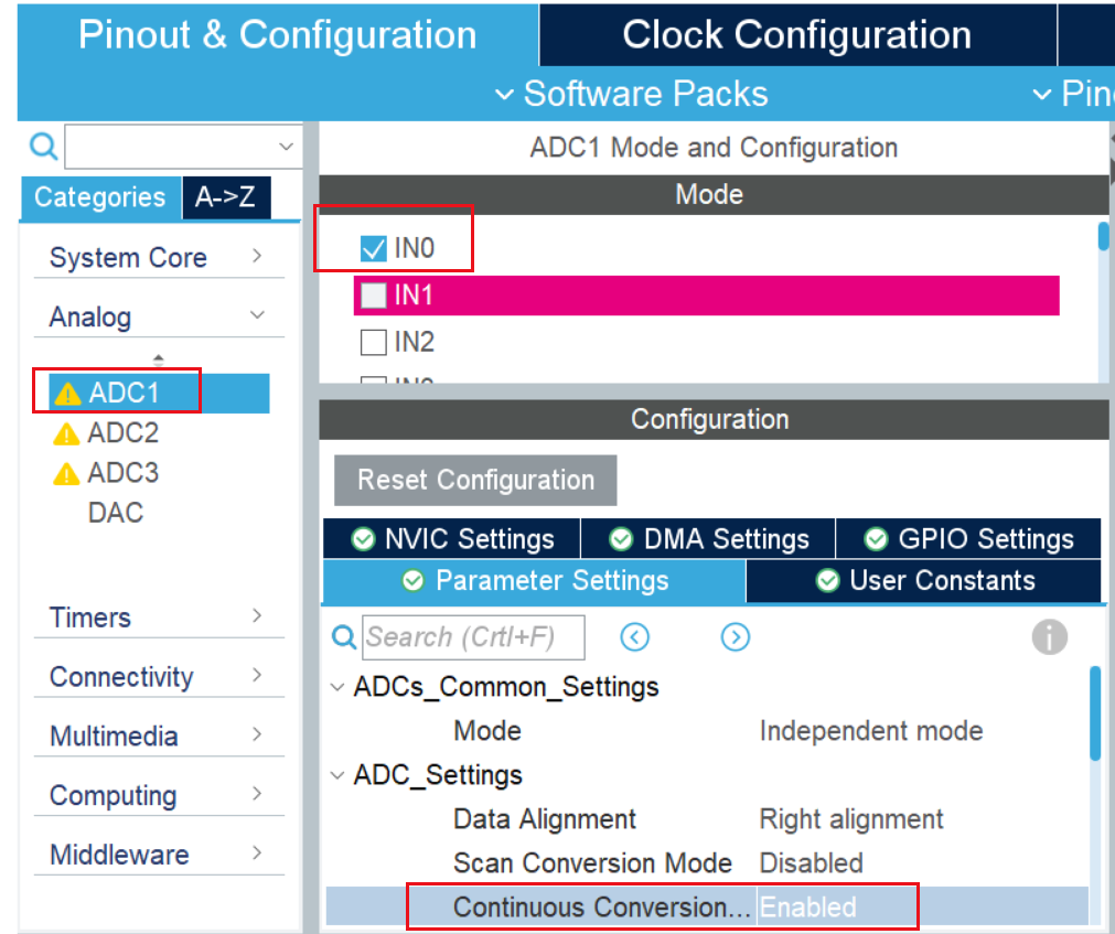
(1) Polling
The CH0 of ADC1 is configured first and enables continuous collection.
while(1)
{
    HAL_ADC_Start(&hadc1);//Start ADC Loading
    HAL_ADC_PollForConversion(&hadc1, 50);//Waiting for conversion to complete, the second parameter represents the time-out, in ms.
    if(HAL_IS_BIT_SET(HAL_ADC_GetState(&hadc1), HAL_ADC_STATE_REG_EOC))
    {
        AD_Value = HAL_ADC_GetValue(&hadc1);//Read ADC conversion data, 12 bits
        printf("[\tmain]info:v=%.1fmv\r\n",AD_Value*3300.0/4096);//Print Log
    }
}
(2) DMA mode
1. Initialize two ADC channels
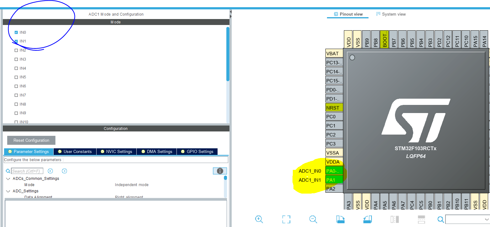
(2) Configuration
Enables Continuous Conversion Mode;
The number of conversion channels selected by the ADC rule group is 2 (Number Of Conversion);
Configure the input channels of Rank to convert channel 0 and channel 1, respectively.
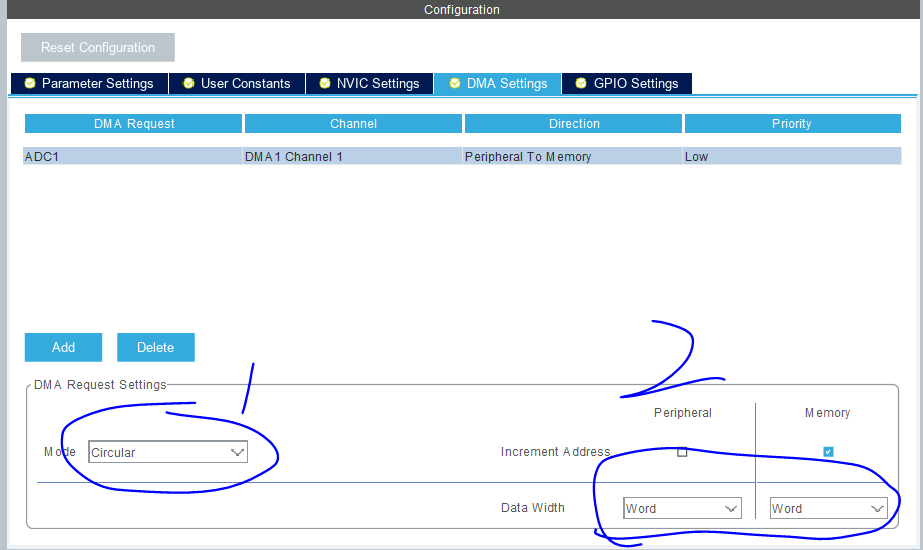
3. Add DMA
Set to continuous transmission mode, data length is word.
(4) Sample code
The data of array even subscript is channel 0, and the data of array odd subscript is channel 1.
In the program, the even subscript data of the array is added together to find the average value, and then the data is converted to the voltage value, that is, the voltage value of the PA0 pin. The same is true for another channel.
uint32_t ADC_Value[100];  //Data Cache Array
uint8_t i;
uint32_t ad1, ad2;  //ad1 stores the voltage value of PA0; ad2 stores the voltage value of PA1

int main(void)
{
  HAL_Init();

  SystemClock_Config();

  MX_GPIO_Init();
  MX_USART1_UART_Init();
  MX_TIM1_Init();
  MX_DMA_Init();
  MX_ADC1_Init();

  HAL_TIM_Base_Start_IT(&htim1);
# Turn on ADC conversion by DMA. The second parameter is the starting address of the data store, and the third parameter is the length of the data transmitted by DMA.
  HAL_ADC_Start_DMA(&hadc1, (uint32_t*)&ADC_Value, 100);
  while (1)
  {
    HAL_Delay(500);
    for(i = 0,ad1 =0,ad2=0; i < 100;)
    {
        ad1 += ADC_Value[i++];
        ad2 += ADC_Value[i++];
    }
    ad1 /= 50;
    ad2 /= 50;
    printf("\r\n********ADC-DMA-Example********\r\n");
    printf("[\tmain]info:AD1_value=%1.3fV\r\n", ad1*3.3f/4096);
    printf("[\tmain]info:AD2_value=%1.3fV\r\n", ad2*3.3f/4096);
  }