From: https://blog.csdn.net/qq_29350001/article/details/81558649
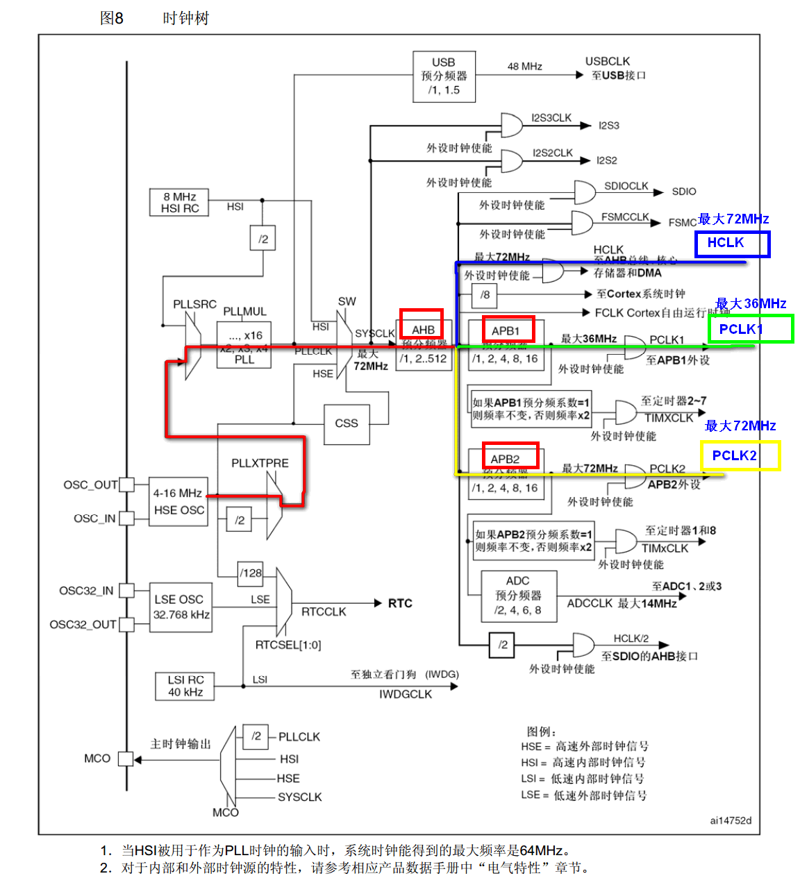
I. Clock system block diagram
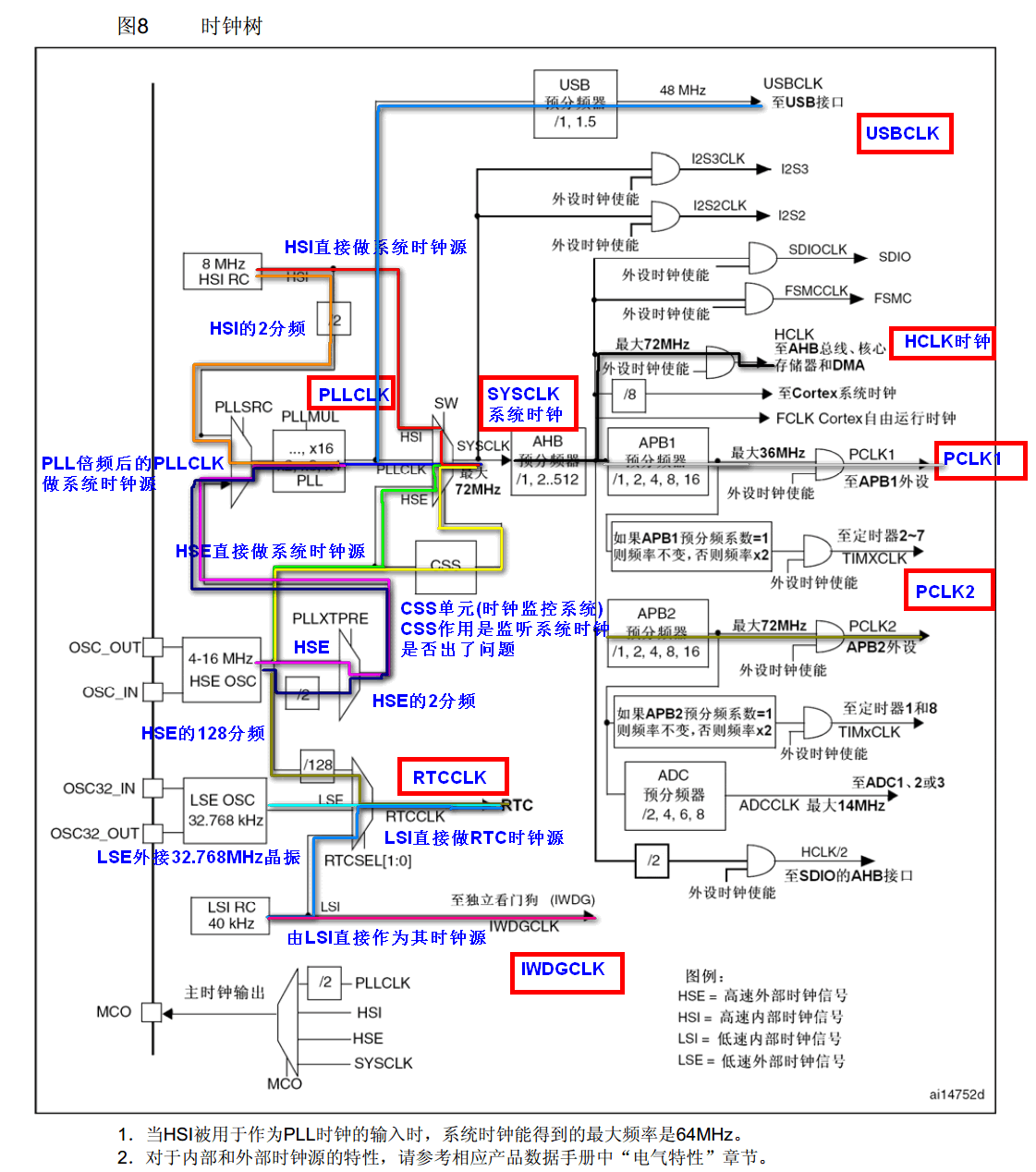
II. Clock System
- STM32 has five clock sources: HSI, HSE, LSI, LSE, PLL.
(1) HSI is a high-speed internal clock, RC oscillator, with a frequency of 8MHz and low accuracy.
(2) HSE is a high-speed external clock, which can be connected with quartz/ceramic resonator or external clock source. Its frequency range is from 4MHz to 16MHz.
(3) LSI is a low-speed internal clock, RC oscillator, with a frequency of 40 kHz, providing a low-power clock.
(4) LSE is a low-speed external clock connected to 32.768 kHz quartz crystal.
(5) PLL is the frequency doubling output of PLL, and its clock input source can be HSI/2, HSE or HSE/2. Frequency doubling can be chosen as 2 to 16 times, but the maximum output frequency should not exceed 72MHz. - The system clock SYSCLK can be derived from three clock sources:
(1) HSI oscillator clock
(2) HSE oscillator clock
3. PLL Clock - STM32 can choose a clock signal to output to MCO foot (PA8), and can choose 2-frequency, HSI, HSE, or system clock for PLL output.
- Before any peripheral can be used, its corresponding clock must be enabled first.
3. RCC-related configuration registers
        /**
          * @brief Reset and Clock Control
          */
        typedef struct
        {
          __IO uint32_t CR;           // Enabling and Readiness Markers for HSI,HSE,CSS,PLL, etc.
          __IO uint32_t CFGR;         // Clock Source Selection, Frequency Division Coefficient Setting for PLL, etc.
          __IO uint32_t CIR;          // Clear/enable clock ready interrupt
          __IO uint32_t APB2RSTR;     // APB2 Line External Reset Register
          __IO uint32_t APB1RSTR;     // The peripheral reset register on APB1 line
          __IO uint32_t AHBENR;       // Clock Enablation for DMA, SDIO, etc.
          __IO uint32_t APB2ENR;      // APB2 Line Peripheral Clock Enablation
          __IO uint32_t APB1ENR;      // Peripheral Clock Enablation on APB1 Line
          __IO uint32_t BDCR;         // Backup Domain Control Register
          __IO uint32_t CSR;          // Control State Register

        #ifdef STM32F10X_CL
          __IO uint32_t AHBRSTR;
          __IO uint32_t CFGR2;
        #endif /* STM32F10X_CL */

        #if defined (STM32F10X_LD_VL) || defined (STM32F10X_MD_VL) || defined (STM32F10X_HD_VL)
          uint32_t RESERVED0;
          __IO uint32_t CFGR2;
        #endif /* STM32F10X_LD_VL || STM32F10X_MD_VL || STM32F10X_HD_VL */
        } RCC_TypeDef;
IV. RCC Related Header Files and Firmware Library Resources
Where file: stm32f10x_rcc.c
Clock enabling configuration:
     RCC_LSEConfig() ,RCC_HSEConfig(),
     RCC_HSICmd() , RCC_LSICmd() , RCC_PLLCmd() ......
Clock Source Related Configuration:
     RCC_PLLConfig (), RCC_SYSCLKConfig() ,
     RCC_RTCCLKConfig() ...
Frequency division coefficient selection configuration:
RCC_HCLKConfig() , RCC_PCLK1Config() , RCC_PCLK2Config()...
Peripheral Clock Enables:
      RCC_APB1PeriphClockCmd():  //Peripheral Clock Enablation on APB1 Line
     RCC_APB2PeriphClockCmd();  //APB2 Line Peripheral Clock Enablation
     RCC_AHBPeriphClockCmd();   //Peripheral Clock Enablation on AHB Line
Other peripheral clock enabling
RCC_ADCCLKConfig (); RCC_RTCCLKConfig();
State parameter acquisition
     RCC_GetClocksFreq();
     RCC_GetSYSCLKSource();
     RCC_GetFlagStatus()
RCC interrupt correlation function:
RCC_ITConfig() , RCC_GetITStatus() , RCC_ClearITPendingBit()...
V. System Clock Initialization
System clock initialization function: System Init ();
6. Summarize the process of system initialization function
- Open HSE, wait for ready, set Flash wait operation
- Set the frequency dividing coefficients of AHB, APB1 and APB2 to determine the relationship between them and the system clock.
- Setting CFGR register to determine PLL clock source and frequency doubling coefficient (HSE external 8M*9 times = 72MHz)
- Enabling PLL to switch system clock source to PLL
Note:
** APB(Advanced Peripheral Bus),** On-Chip Peripheral Bus. Mainly used for communication between slow on-chip peripherals and ARM core
** AHB(Advanced High performance Bus),** High Performance Bus. Mainly used for high performance, high clock rate inter-module communication of the system