DHT11 module
DHT11 is a wet temperature integrated digital sensor. The sensor includes a resistive humidity measuring element and an NTC temperature measuring element, and is connected with a high-performance 8-bit single chip microcomputer. Through the simple circuit connection of MCU and other microprocessors, the local humidity and temperature can be collected in real time. DHT11 and MCU can use a simple single bus for communication, which only needs an I/O port. The 40Bit data of humidity and temperature data inside the sensor is transmitted to the single chip microcomputer at one time. The data is verified by checksum to effectively ensure the accuracy of data transmission. The power consumption of DHT11 is very low. Under 5V power supply voltage, the average maximum current is 0.5mA.
The technical parameters of DHT11 are as follows:
- Working voltage range: 3.3V-5.5V
- Operating current: average 0.5mA
- Output: single bus digital signal
- Measurement range: humidity 20 ~ 90% RH, temperature 0 ~ 50 ℃
- Accuracy: humidity ± 5%, temperature ± 2 ℃
- Resolution: humidity 1%, temperature 1 ℃
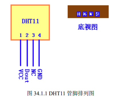
The pin arrangement of DHT11 is shown in figure 34.1.1:
Although DHT11 is similar to DS18B20 in terms of single bus access, the access of DHT11 is relatively lower than that of DS18B20
It's much simpler. Let's take a look at the data structure of DHT11.
DHT11 digital wet temperature sensor adopts single bus data format. That is, a single data pin port completes the bidirectional transmission of input and output. Its data packet consists of 5Byte (40bit). The data is divided into decimal part and integer part. A complete data transmission is 40bit, with high-order first out. The data format of DHT11 is: 8bit humidity integer data + 8bit humidity decimal data + 8bit temperature integer data + 8bit temperature decimal data + 8bit checksum. The checksum data is the sum of the first four bytes.
The sensor data output is uncoded binary data. Data (humidity, temperature, integer, decimal) should be separated
handle. For example, the data read from DHT11 is shown in figure 34.1.2:
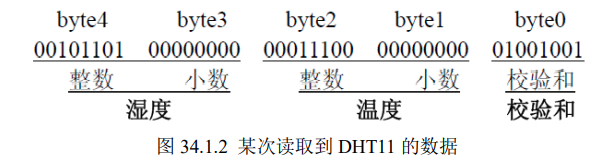
The values of humidity and temperature can be obtained from the above data. The calculation method is as follows:
Humidity = byte4 byte3=45.0 (%RH)
Temperature = byte2 byte1=28.0 ( ℃)
Verification = byte4+ byte3+ byte2+ byte1=73(= humidity + temperature) (correct verification)
It can be seen that the data format of DHT11 is very simple. The maximum one-time communication between DHT11 and MCU is about 3ms. It is recommended that the continuous reading interval of the host should not be less than 100ms.
Transmission timing of DHT11
The data transmission process of DHT11 is shown in figure 34.1.3:
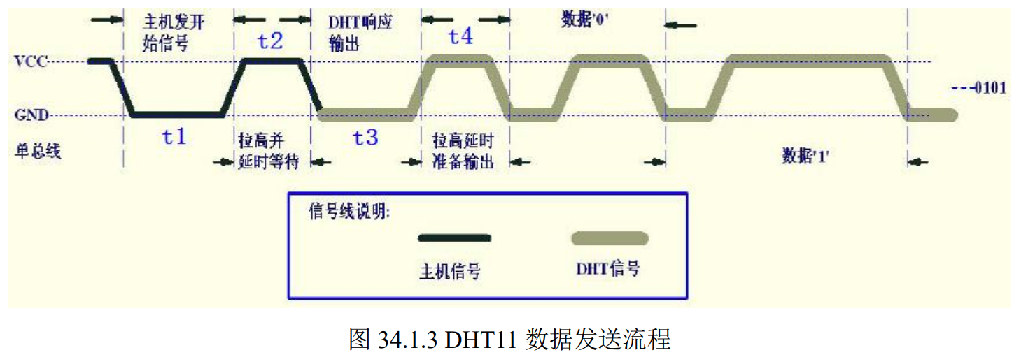
First, the host sends the start signal, that is, pull down the data line and hold t1 (at least 18ms), then pull up the data line t2 (20~40us) time, and then read the response of DHT11. Normally, DHT11 will pull down the data line and hold t3 (40~50us) time as the response signal, and then DHT11 will pull up the data line and hold t4 (40~50us) time to start outputting data.
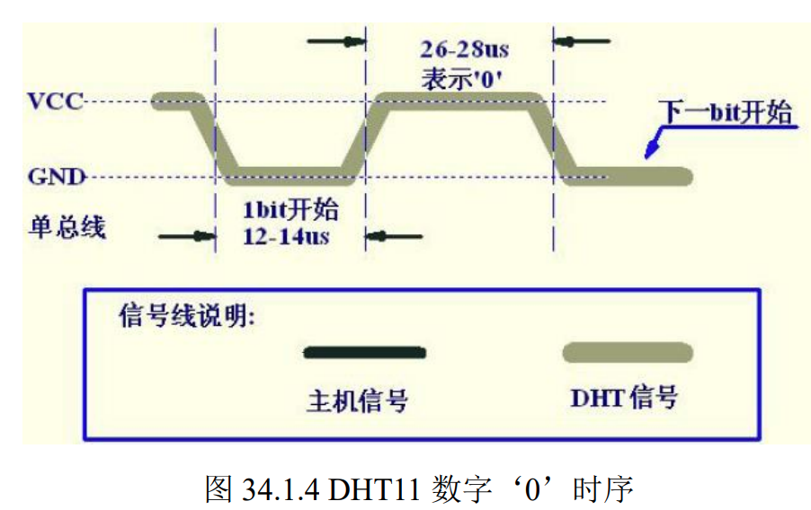
The timing of DHT11 output digital '0' is shown in figure 34.1.4:
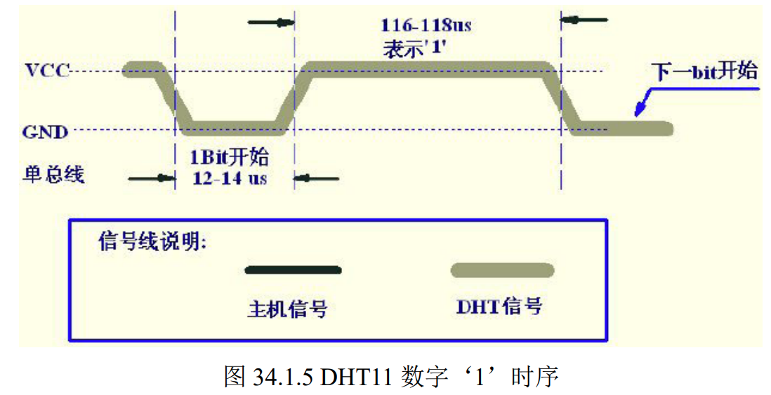
The timing of DHT11 output digital '1' is shown in figure 34.1.5:
Through the above understanding, we can read DHT311 through STM32. For more details, please refer to the data manual of DHT11
stm32 code
dht11.h code
#ifndef __DHT11_H
#define __DHT11_H
#include "sys.h"

//IO direction setting
#define DHT11_IO_IN()  {GPIOG->CRH&=0XFFFF0FFF;GPIOG->CRH|=8<<12;}
#define DHT11_IO_OUT() {GPIOG->CRH&=0XFFFF0FFF;GPIOG->CRH|=3<<12;}
IO Operation function
#define 	 DHT11_DQ_OUT PGout(11) / / data port 	 PA0
#define 	 DHT11_ DQ_ In pgin (11) / / data port 	 PA0


u8 DHT11_Init(void);//Initialize DHT11
u8 DHT11_Read_Data(u8 *temp,u8 *humi);//Read temperature and humidity
u8 DHT11_Read_Byte(void);//Read a byte
u8 DHT11_Read_Bit(void);//Read one bit
u8 DHT11_Check(void);//Detect the presence of DHT11
void DHT11_Rst(void);//Reset DHT11
#endif
dht11.c code
#include "dht11.h"
#include "delay.h"


//Reset DHT11
void DHT11_Rst(void)
{
	DHT11_IO_OUT(); 	//SET OUTPUT
    DHT11_DQ_OUT=0; 	//Pull down DQ
    delay_ms(20);    	//Pull down for at least 18ms
    DHT11_DQ_OUT=1; 	//DQ=1
	delay_us(30);     	//The main engine is pulled up by 20~40us
}
//Waiting for a response from DHT11
//Return 1: the existence of DHT11 is not detected
//Return 0: exists
u8 DHT11_Check(void)
{
	u8 retry=0;
	DHT11_IO_IN();//SET INPUT
    while (DHT11_DQ_IN&&retry<100)//DHT11 will pull down 40~80us
	{
		retry++;
		delay_us(1);
	};
	if(retry>=100)return 1;
	else retry=0;
    while (!DHT11_DQ_IN&&retry<100)//After DHT11 is pulled down, it will be pulled up by 40~80us again
	{
		retry++;
		delay_us(1);
	};
	if(retry>=100)return 1;
	return 0;
}
//Read a bit from DHT11
//Return value: 1 / 0
u8 DHT11_Read_Bit(void)
{
 	u8 retry=0;
	while(DHT11_DQ_IN&&retry<100)//Wait for low level
	{
		retry++;
		delay_us(1);
	}
	retry=0;
	while(!DHT11_DQ_IN&&retry<100)//Wait for high level
	{
		retry++;
		delay_us(1);
	}
	delay_us(40);//Wait 40us
	if(DHT11_DQ_IN)return 1;
	else return 0;
}
//Read a byte from DHT11
//Return value: read data
u8 DHT11_Read_Byte(void)
{
    u8 i,dat;
    dat=0;
	for (i=0;i<8;i++)
	{
   		dat<<=1;
	    dat|=DHT11_Read_Bit();
    }
    return dat;
}
//Read data from DHT11 once
//temp: temperature value (range: 0 ~ 50 °)
//humi: humidity value (range: 20% ~ 90%)
//Return value: 0, normal; 1. Read failed
u8 DHT11_Read_Data(u8 *temp,u8 *humi)
{
 	u8 buf[5];
	u8 i;
	DHT11_Rst();
	if(DHT11_Check()==0)
	{
		for(i=0;i<5;i++)//Read 40 bit data
		{
			buf[i]=DHT11_Read_Byte();
		}
		if((buf[0]+buf[1]+buf[2]+buf[3])==buf[4])
		{
			*humi=buf[0];
			*temp=buf[2];
		}
	}else return 1;
	return 0;
}
//Initialize the IO port DQ of DHT11 and detect the existence of DHT11 at the same time
//Return 1: does not exist
//Return 0: exists
u8 DHT11_Init(void)
{
 	GPIO_InitTypeDef  GPIO_InitStructure;

 	RCC_APB2PeriphClockCmd(RCC_APB2Periph_GPIOG, ENABLE);	 //Enable PG port clock

 	GPIO_InitStructure.GPIO_Pin = GPIO_Pin_11;				 //PG11 port configuration
 	GPIO_InitStructure.GPIO_Mode = GPIO_Mode_Out_PP; 		 //Push pull output
 	GPIO_InitStructure.GPIO_Speed = GPIO_Speed_50MHz;
 	GPIO_Init(GPIOG, &GPIO_InitStructure);				 //Initialize IO port
 	GPIO_SetBits(GPIOG,GPIO_Pin_11);						 //PG11 output high

	DHT11_Rst();  //Reset DHT11
	return DHT11_Check();//Waiting for a response from DHT11
}
main.c code
#include "led.h"
#include "delay.h"
#include "sys.h"
#include "usart.h"
#include "includes.h"
#include "beep.h"
#include "key.h"
#include "dht11.h"
#include <stdio.h>
int main(void)
{
u8 buf;
u8 temp;
int rt=0;
delay_init(); //Delay initialization
NVIC_PriorityGroupConfig(NVIC_PriorityGroup_2); //Interrupt packet configuration
Usart_Init(); //Serial port baud rate setting
DHT11_Init(); //Temperature and humidity initialization
delay_ms(5000);
while(1)
{
rt = DHT11_Read_Data(&temp,&buf);
if(rt==0)
{
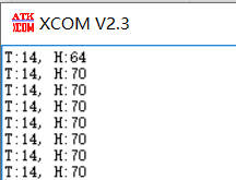
printf("T:%d, H:%d\r\n",temp,buf);
}
else
{
printf("err:%d\r\n",rt);
}
delay_ms(5000);
}
}
T is the temperature and H is the humidity
Operation results