STM32 double shaft rocker control hollow cup motor
Biaxial rocker sensor
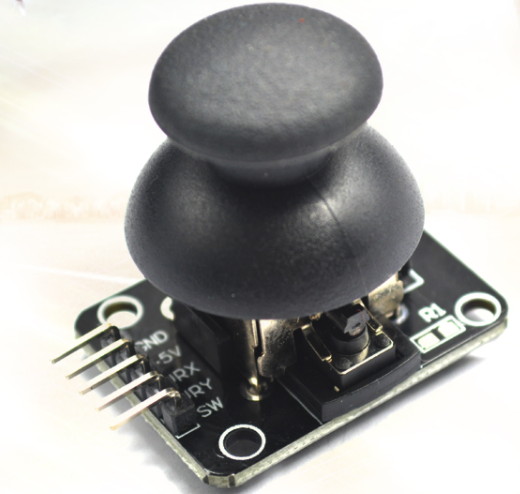
the PS2 two axis key game rocker module adopts the metal key rocker potentiometer on the PS2 game handle. The module has two analog output and one digital output interfaces, and the output values correspond respectively( ×, Y double axis offset, its type is analog, the key indicates whether the user presses on the z axis, its type is digital switching value, module integrated power indicator, it can display the working state, the coordinate identifier is clear and concise, accurate positioning, it can easily control the movement of objects (such as two degree of freedom steering gear pan tilt) in two-dimensional space, so it can be programmed by the controller Plug in the sensor expansion board and complete creative remote control interactive works.
Hardware interface:
GND – GND
+5V – +5v
VRX – analog quantity in x direction
VRY – analog quantity in y direction
SW -- key state
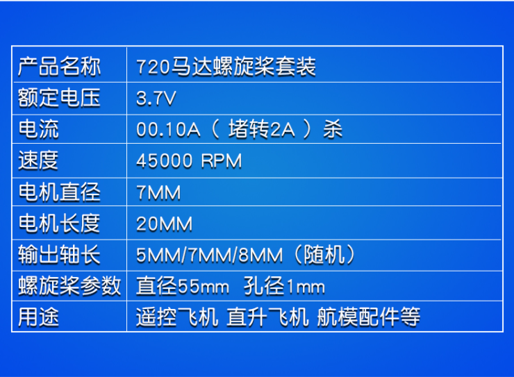
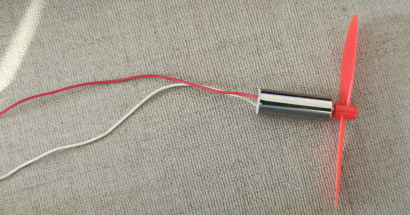
720 hollow cup motor
the hollow cup motor has fast speed and small volume. It is suitable for remote control aircraft model production with propeller. DIY electronic technology production has simple wiring. It is an accessory for micro four-axis aircraft. Simple to use: hollow cup motor, Qin iron boron strong magnetic property is more stable.
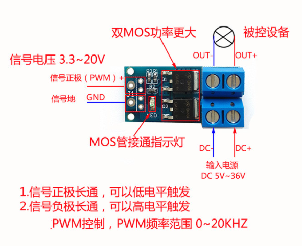
Motor drive module
(1) MOS FET drive module adopts original imported dual MOS parallel active output, with lower internal resistance, high current and strong power. It is 15A and 400W at room temperature, which meets the use of most equipment;
(2) wide voltage, supporting PWM;1: Working voltage: DC 5V – 36V;
(3) trigger signal source: digital quantity high and low level (DC3.3v – 20V), which can be connected to MCU IO port, PLC interface, DC power supply, PWM signal, and the signal frequency is 0 – 20KHZ.
(4) output capacity: DC 5V – 36V, continuous current 15A at room temperature, Power 400W! Under the condition of auxiliary heat dissipation, the maximum current can reach 30A.
(5) application: the output end can control high-power equipment, motor, bulb, LED lamp belt, DC motor, micro water pump, solenoid valve, etc. PWM can be input to control motor speed, lamp self brightness, etc.
software design
timer 3 channel 1(PA6) outputs PWM wave to complete motor control
/*****************PWM Wave output*****************
**Formal parameter: u16 psc -- prescaled coefficient
**			u16 arr -- PWM One cycle time
**			u16 ccr -- Duty cycle
**Example: Tim3_CH1_PWM(72,1000,200)
**PWM Cycle time: 1000us
**Duty cycle: 200 / 1000 * 100% = 20%
**High level time: 200US, low level time: 800us
*********************************************/
void Tim3_CH1_PWM(u16 psc,u16 arr,u16 ccr)
{
	//1. Turn on the clock
	RCC->APB1ENR|=1<<1;//TIM3
	RCC->APB1RSTR|=1<<1;//On reset clock
	RCC->APB1RSTR&=~(1<<1);//Off reset
	RCC->APB2ENR|=1<<2;//PA
	/*2.Configure GPIO port*/
	GPIOA->CRL&=0xf0ffffff;
	GPIOA->CRL|=0x0B000000;//Multiplex push-pull output
	/*3.Configure core registers*/
	TIM3->CNT=0;//Clear the value in the counter
	TIM3->PSC=psc-1;//Prescaler coefficient
	TIM3->ARR=arr;//Reload value
	TIM3->CR1|=0x1<<7;//Allowable position of automatic reloading and preloading
	TIM3->CCMR1&=~(0x3<<0);//OC1 configured as output
	TIM3->CCMR1|=0x1<<3;//Output comparison 1 preload enable
	TIM3->CCMR1|=0x6<<4;//PWM mode 1, CNT < CCR1 is the effective level
	TIM3->CCER&=~(1<<1);//The active level is high
	TIM3->CCR1=ccr;
	TIM3->CCER|=1<<0;//Output enable
	TIM3->CR1|=1<<0;//Enable TIM3
}
ADC1 regular channel collects remote control x-axis analog value
/****************ADC Regular channel configuration*******************
**
**Hardware interface: PB0 --ADC1_CH8
**
*****************************************************/
void ADC_Regular_Channel(void)
{
    /*1.Turn on the clock*/
    RCC->APB2ENR|=1<<3;//PB clock
    RCC->APB2ENR|=1<<9;//ADC1 clock
    RCC->APB2RSTR|=1<<9;//ADC1 reset
    RCC->APB2RSTR&=~(1<<9);//Cancel reset
    /*2.Configure GPIO port*/
    GPIOB->CRL&=0xFFFFFFF0;//Configure as analog input
    /*Configure ADC operating frequency*/
    RCC->CFGR&=~(0x3<<14);//Clear the value in the original register
    RCC->CFGR|=0x2<<14;//ADC working frequency: 72MHZ/6=12MHZ
    /*3.ADC Core register configuration*/
//    ADC1->CR1&=~(0xF<<16);// Independent mode
//    ADC1->CR1&=~(1<<8);// Turn off scan mode
    ADC1->CR2|=1<<23;//Collect internal temperature data
    ADC1->CR2|=1<<20;//Start transformation with external events
    ADC1->CR2|=0x7<<17;//Select SWSTART event conversion channel
//    ADC1->CR2&=~(1<<11);// Right align
//    ADC1->CR2|=1<<1;// Continuous conversion mode
    ADC1->SMPR1|=0x7<<18;//Set internal temperature sampling time, channel 16
    ADC1->SMPR2|=0X7<<24;//Channel 8 sampling time
    ADC1->SQR1&=~(0xF<<20);//Set the number of passes for a single conversion to 1
    ADC1->CR2|=1<<0;//Turn on ADC
    ADC1->CR2|=1<<3;//Initialize calibration register
    while(ADC1->CR2&1<<3);//Wait for initialization to complete
    ADC1->CR2|=1<<2;//Start calibration
    while(ADC1->CR2&1<<2);//Wait for calibration to complete

}
/*******************Get rule channel conversion*****************
**
**Formal parameter: u8 chx --- channel number to be converted (0 ~ 17)
**Return value: data converted successfully (12 bits)
**
******************************************************/
u16 ADC1_GetRegular_Channel_Data(u8 chx)
{
    u16 dat;
    ADC1->SQR3&=~(0x1F<<0*5);//Clears the value in the first conversion sequence
    ADC1->SQR3|=chx<<0*5;//Set the channel number to be converted
    ADC1->CR2|=1<<22;//Open conversion rule channel
    while(!(ADC1->SR&1<<1)){}//Wait for the rule channel conversion to complete
    dat=ADC1->DR;
    return dat;
}
main function
int main()
{
	int data=0;
	float data2=0;
	Usartx_Init(USART1,115200,72);
	TIMx_Init(TIM2,72,20*1000);
	TIM3_CHx_PWM(1,3600,data);//1 screen, cycle 50ms(20khz)
	ADC_Regular_Channel();//Rule channel initialization
	while(1)
	{
    data=ADC1_GetRegular_Channel_Data(8);//Complete regular channel conversion
    data-=2054;
    data2=data*1.0/4095*3600;
    TIM3->CCR1=data2;
	}
}
Example effect
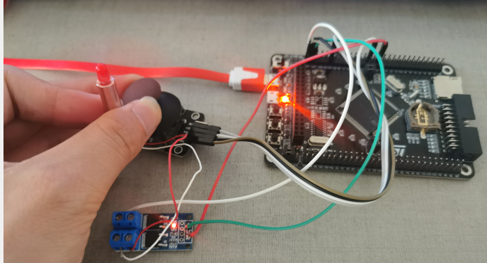
Project example: