STM32 drives WS2812B-2020 RGB color lamp (II)
In the previous section, we briefly analyzed some hardware driving principles of WS2812B-2020 color lights, and sorted out the driving ideas.
Refer to the previous article for details: STM32 drives WS2812B-2020 RGB color lamp (I)
Next, we analyze step by step how to use code to light the color lights, and further realize the rainbow light effect.
Last time, we have analyzed the conditions of how to light the lamp, that is, we need to give a signal with a fixed duty cycle in one cycle. This signal is a bit bit, representing a 0 or a 1. If 24 signals are sent continuously, it will form the color value of an RGB lamp.
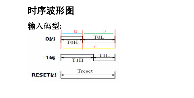
As shown in the figure above, we still use the sequence diagram of WS2812B as an example. t1 marked in the figure refers to how long this 0 takes when the transmission bit is 0, which is a cycle to be used; t2 refers to the duration of high level in the cycle of transmission 0; Similarly, t3 refers to the duration of low level in the cycle of transmission 0.
The specific understanding here has been mentioned in the previous article. How much is appropriate for this cycle? In combination with datasheet, there is an 800K transmission rate, that is, the rate of transmitting a bit, which is converted into a time of 1.25us. First try a 1.25us cycle here, t1=1.25us. Note that the period of 1.25us here is the pulse period of PWM!! It needs to be different from the clock cycle we analyze later!
The following is a detailed analysis of the concepts of clock cycle and pulse cycle: the main frequency of the main control we use is 72MHz, and the calculation period is 1/72us ≈ 13.89ns. We record this time as T, which is the clock cycle. It is the clock cycle that the whole system needs to refer to, including the pulse cycle in the PWM that needs to be set, and it also needs to refer to this clock cycle. If you want to know the clock, please refer to the clock tree system of STM32:
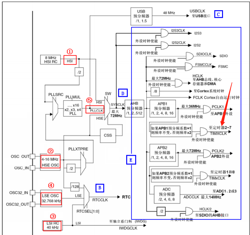
The arrow in the figure refers to the timer we use. Its clock source comes from AHB. In this example, APB1 does not divide the frequency, so the TIMXCLK clock is equal to SYSCLK, that is, 72MHz. Of course, this is not the focus of our explanation.
The next focus is PWM. I understand the specific principles. We need to use two parameters: one is count and the other is dummy. For these two parameters, count is the count value. The value of the AR register (reload register) corresponding to this value in the DATASHEET of STM32 is used to determine our pulse cycle, that is, the value of t1 (it should be noted that count is an accumulated value, and the time used for each increase of 1 is the clock cycle t mentioned above); Another value, dummy, is the so-called duty cycle, that is, the duration of high level in a PWM pulse cycle, that is, the value of t2, corresponds to the CCR (capture / comparison register) in the STM32 manual. Refer to the figure below
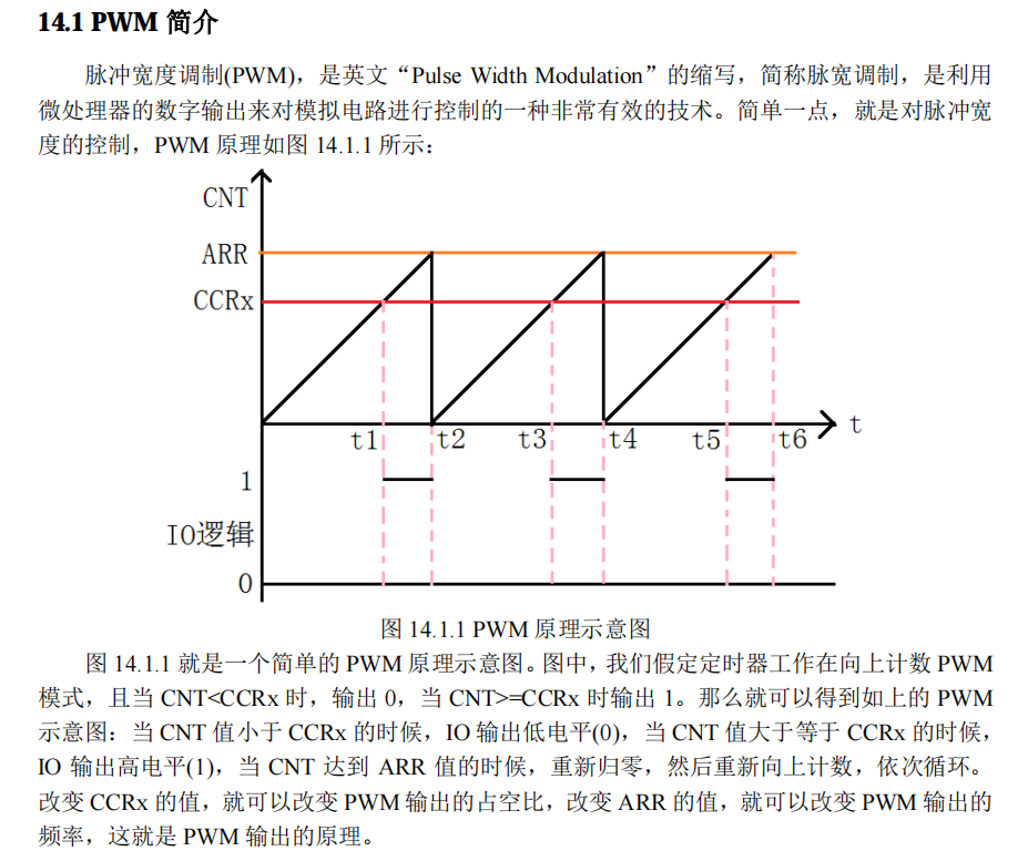
So, how to get the value of this count?
We just analyzed that the clock cycle is 13.89ns and the pulse cycle is 1.25us. That is, after N clock cycles, I can reach a pulse cycle. N here is the amount count we need. After calculation, the value of count is 90.
Here, you need to refer to the specific time required for high and low levels listed in the datasheet. Give the table again:
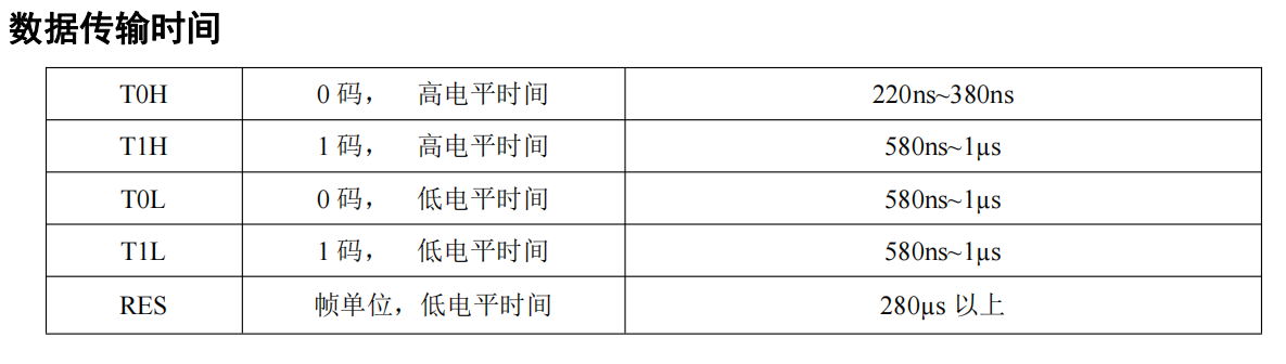
Take the "0" code as an example. The time required for high level is 220ns-380ns, and M clock cycles are required to reach this time length, which is obviously a range. That is M*13.89=220 ~ 380. Here, give a value of 25. The calculated high-level time is 347.25ns, which is within the range. Then determine the low-level time: 1250-347.25=902.75ns. Compared with the range (580ns ~ 1us), it is obvious that this value also meets the requirements. Then 25 determined here is the count value of the duration of high level required for "0" code, that is, the duty cycle. This value is finally written to the CCR of the timer through DMA.
Similarly, the duty cycle of "1" code is calculated to be 45. This value can be taken within a range as long as the calculated time of high and low levels meets the time listed in the above table. If you can't understand, you can leave a message for discussion.
The next thing we need to do is configure PWM. The whole configuration is completed in CUBEMX.
In the routine, we use channel 1 of TIM4
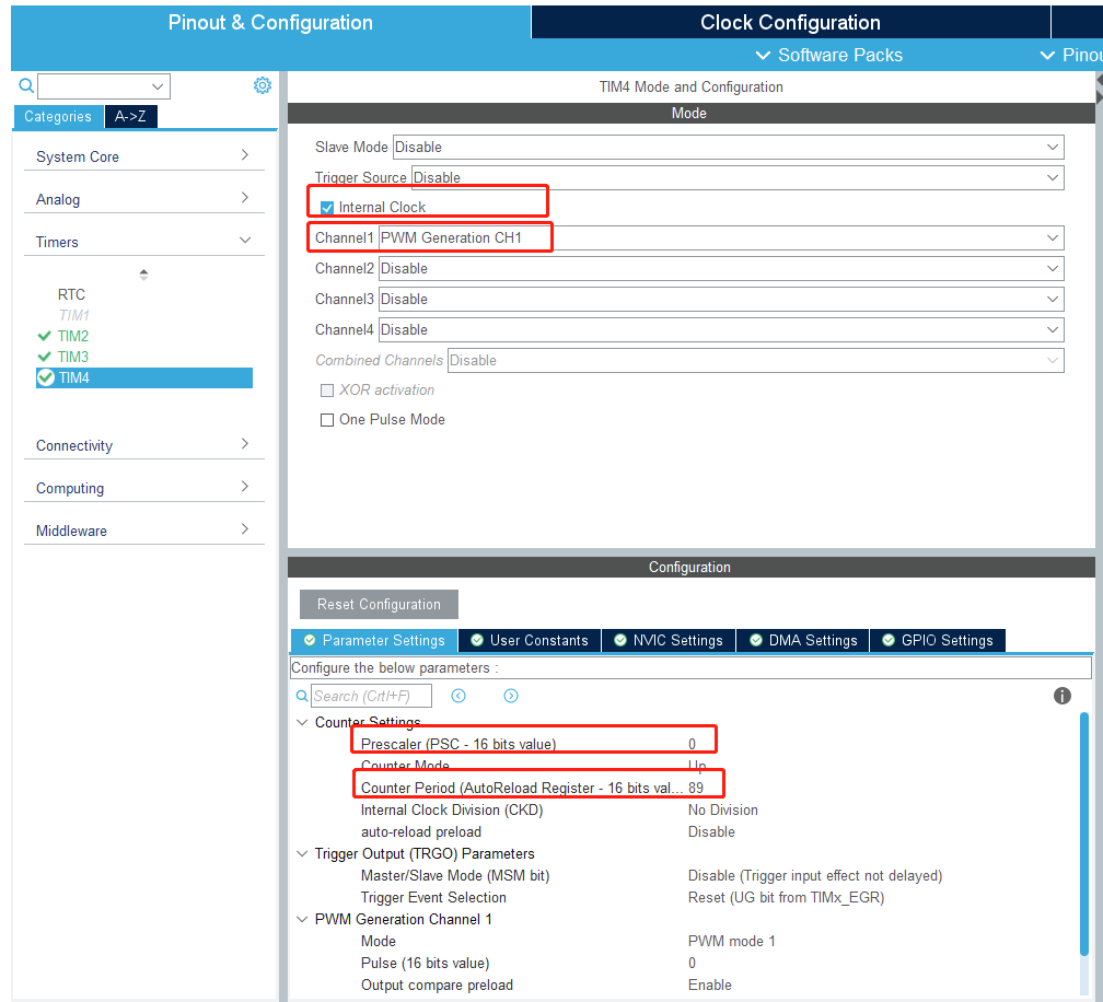
First configure the clock source, then the channel, and then do not divide the frequency. The counter period is 89, because 1 needs to be added during calculation.
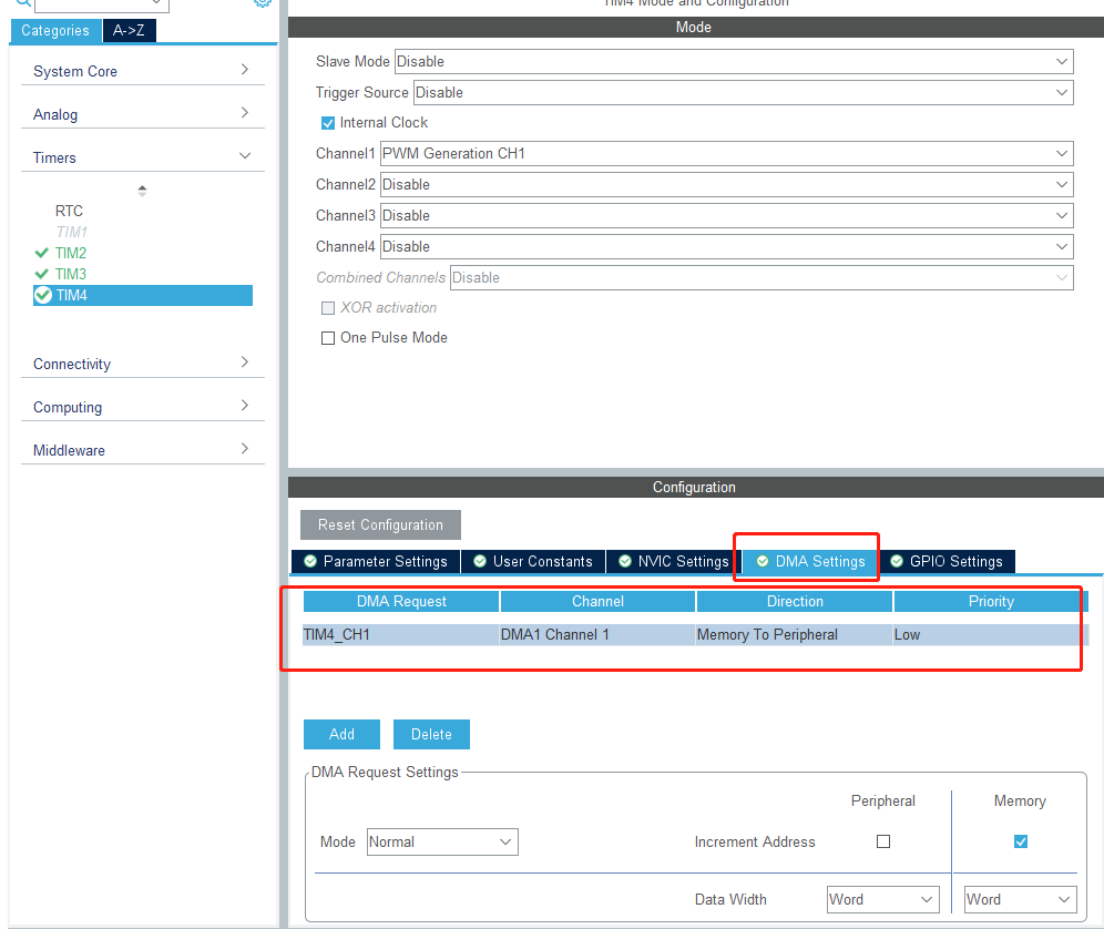
Then talk about this. DMA(Direct Memory Access) means that data can be transferred directly between memory and peripherals without going through CPU. The DMA output transmission direction we set here is from memory to peripherals. In the memory, we need to define a storage space, such as an array, and then store 24bit color data in this array. When configuring DMA, we use the address of the array defined here. The peripheral is the acquisition / comparison register CCR of PWM generated by TIM. Then take a look at the DMA configuration:
After the basic configuration is completed, you can generate code. See below:
void HAL_TIM_Base_MspInit(TIM_HandleTypeDef* tim_baseHandle)
{

  if(tim_baseHandle->Instance==TIM2)
  {
  /* USER CODE BEGIN TIM2_MspInit 0 */

  /* USER CODE END TIM2_MspInit 0 */
    /* TIM2 clock enable */
    __HAL_RCC_TIM2_CLK_ENABLE();
  /* USER CODE BEGIN TIM2_MspInit 1 */

  /* USER CODE END TIM2_MspInit 1 */
  }
  else if(tim_baseHandle->Instance==TIM3)
  {
  /* USER CODE BEGIN TIM3_MspInit 0 */

  /* USER CODE END TIM3_MspInit 0 */
    /* TIM3 clock enable */
    __HAL_RCC_TIM3_CLK_ENABLE();
  /* USER CODE BEGIN TIM3_MspInit 1 */

  /* USER CODE END TIM3_MspInit 1 */
  }
  else if(tim_baseHandle->Instance==TIM4)
  {
  /* USER CODE BEGIN TIM4_MspInit 0 */

  /* USER CODE END TIM4_MspInit 0 */
    /* TIM4 clock enable */
    __HAL_RCC_TIM4_CLK_ENABLE();

    /* TIM4 DMA Init */
    /* TIM4_CH1 Init */
    hdma_tim4_ch1.Instance = DMA1_Channel1;
    hdma_tim4_ch1.Init.Direction = DMA_MEMORY_TO_PERIPH;
    hdma_tim4_ch1.Init.PeriphInc = DMA_PINC_DISABLE;
    hdma_tim4_ch1.Init.MemInc = DMA_MINC_ENABLE;
    hdma_tim4_ch1.Init.PeriphDataAlignment = DMA_PDATAALIGN_WORD;
    hdma_tim4_ch1.Init.MemDataAlignment = DMA_MDATAALIGN_WORD;
    hdma_tim4_ch1.Init.Mode = DMA_NORMAL;
    hdma_tim4_ch1.Init.Priority = DMA_PRIORITY_LOW;
    if (HAL_DMA_Init(&hdma_tim4_ch1) != HAL_OK)
    {
      Error_Handler();
    }

    __HAL_LINKDMA(tim_baseHandle,hdma[TIM_DMA_ID_CC1],hdma_tim4_ch1);

  /* USER CODE BEGIN TIM4_MspInit 1 */

  /* USER CODE END TIM4_MspInit 1 */
  }
}
Here is the configuration of DMA part, and then prepare to see if the light can be turned on.
#define WS2812B_LED_QUANTITY	8

uint32_t WS2812B_Buf[WS2812B_LED_QUANTITY];	//0xGGRRBB
uint32_t WS2812B_Bit[24*WS2812B_LED_QUANTITY+1];//This is to disassemble the buffer above into bit s
uint8_t WS2812B_Flag;

void WS2812B_IRQHandler(void);


void WS2812B_ClearBuf(void)//Clear all data and turn off the light
{
	uint8_t i;
	for(i=0;i<WS2812B_LED_QUANTITY;i++)
	{
		WS2812B_Buf[i]=0x000000;
	}
}

void WS2812B_SetBuf(uint32_t Color)//Sets the color of the light
{
	uint8_t i;
	for(i=0;i<WS2812B_LED_QUANTITY;i++)
	{
		WS2812B_Buf[i]=Color;
	}
}

void WS2812B_UpdateBuf(void)//Write the set color into the lamp and let it light up
{
	uint8_t i,j;
	for(j=0;j<WS2812B_LED_QUANTITY;j++)
	{
		for(i=0;i<24;i++)
		{
			if(WS2812B_Buf[j]&(0x800000>>i)){WS2812B_Bit[j*24+i+1]=45;}  //BIT bit is set to 1 to set the corresponding duty cycle
			else{WS2812B_Bit[j*24+i+1]=25;}
		}
	}
	HAL_TIM_PWM_Start_DMA(&htim4,TIM_CHANNEL_1,&WS2812B_Bit[0],24*WS2812B_LED_QUANTITY+1);
	//DMA1_Start(24*WS2812B_LED_QUANTITY+1);
	//TIM2_Cmd(ENABLE);
	//while(WS2812B_Flag==0);
	//WS2812B_Flag=0;
}

void HAL_TIM_PWM_PulseFinishedCallback(TIM_HandleTypeDef *htim)//PWM signal transmission completion callback function, which is very important
{
	__HAL_TIM_SET_COMPARE(&htim4,TIM_CHANNEL_1,0);
   HAL_TIM_PWM_Stop_DMA(&htim4, TIM_CHANNEL_1);
	//WS2812B_Flag=1;
}
This part of the code is the verification of all the above contents. If you really understand the contents analyzed above, the code research here is still understandable. Let's talk about the last callback function. In the previous article, we talked about a reset=280us, that is, when writing data to the RGB lamp, we need to give a low level not lower than 280us to make the data effective. It is realized in this. It took a long time to get it done. The specific implementation code is this sentence:__ HAL_ TIM_ SET_ COMPARE(&htim4,TIM_CHANNEL_1,0);
The above can basically light up your lamp. Set the color value for what color you need. If you need a more cool effect, please refer to the following section:
void ColorLight_Mode0(void)
{
	static uint8_t i,Color;
	//ColorLight_Time=6;

	if(i==0)WS2812B_SetBuf((Color));
	if(i==1)WS2812B_SetBuf((255-Color));
	if(i==2)WS2812B_SetBuf((Color)<<8);
	if(i==3)WS2812B_SetBuf((255-Color)<<8);
	if(i==4)WS2812B_SetBuf((Color)<<16);
	if(i==5)WS2812B_SetBuf((255-Color)<<16);
	if(i==6)WS2812B_SetBuf((Color)|((Color)<<8));
	if(i==7)WS2812B_SetBuf((255-Color)|((255-Color)<<8));
	if(i==8)WS2812B_SetBuf((Color)|((Color)<<16));
	if(i==9)WS2812B_SetBuf((255-Color)|((255-Color)<<16));
	if(i==10)WS2812B_SetBuf(((Color)<<8)|((Color)<<16));
	if(i==11)WS2812B_SetBuf(((255-Color)<<8)|((255-Color)<<16));
	if(i==12)WS2812B_SetBuf(((Color))|((Color)<<8)|((Color)<<16));
	if(i==13)WS2812B_SetBuf(((255-Color))|((255-Color)<<8)|((255-Color)<<16));

	Color++;
	if(Color==0)
	{
		i++;
		i%=14;
	}
}

void ColorLight_Mode1(void)
{
	uint8_t i,RandNum;
	uint32_t G,R,B;
	static uint8_t j;
	ColorLight_Time=20;
	for(i=31;i>0;i--)
	{
		WS2812B_Buf[i]=WS2812B_Buf[i-1];
	}

	if(j==0)
	{
		RandNum=rand()%7;
		if(RandNum==0)WS2812B_Buf[0]=0x0000FF;
		if(RandNum==1)WS2812B_Buf[0]=0x00FF00;
		if(RandNum==2)WS2812B_Buf[0]=0xFF0000;
		if(RandNum==3)WS2812B_Buf[0]=0x00FFFF;
		if(RandNum==4)WS2812B_Buf[0]=0xFF00FF;
		if(RandNum==5)WS2812B_Buf[0]=0xFFFF00;
		if(RandNum==6)WS2812B_Buf[0]=0xFFFFFF;
	}
	else if(j<15)
	{
		G=WS2812B_Buf[1]/0x10000%0x100;
		R=WS2812B_Buf[1]/0x100%0x100;
		B=WS2812B_Buf[1]%0x100;
		if(G>20)G-=20;
		if(R>20)R-=20;
		if(B>20)B-=20;
		WS2812B_Buf[0]=(G<<16)|(R<<8)|B;
	}
	else
	{
		WS2812B_Buf[0]=0;
	}

	j++;
	j%=50;
}


void ColorLight_Mode2(void)
{
	uint8_t i;
	static uint8_t j;
	ColorLight_Time=20;
	for(i=31;i>0;i--)
	{
		WS2812B_Buf[i]=WS2812B_Buf[i-1];
	}
	if(j==0)WS2812B_Buf[0]=rand()%0x1000000;
	else WS2812B_Buf[0]=WS2812B_Buf[1];
	j++;
	j%=10;
}

void ColorLight_Mode3(void)
{
	uint8_t i;
	ColorLight_Time=500;
	for(i=0;i<32;i++)
	{
		WS2812B_Buf[i]=rand()%0x1000000;
	}
}
These effects can be easily found. I hope they can help you light up your lights faster. After two days of ink, I finally piled up the article. I forgot a lot of things for a long time. If there are incorrect things, I can put forward corrections.
The moon is bright and the stars are sparse. Black magpies fly south